AES256GCM10G25G IP Demo Instruction on KR260
3 Command detail and testing result
This document describes the instruction to demonstrate the operation of AES256GCM10G25GIP on Kria KR260 Robotics Starter Kit. In the demonstration, AES256GCM10G25GIP is used to encrypt/decrypt data between two memories in FPGA and provide authentication tag. User can fill memory with Additional Authenticated Data (AAD), DataIn patterns, set encryption/decryption key, Initialization Vector (IV), and control test operation via serial console.
1 Environment Setup
To operate AES256GCM10G25GIP demo, please prepare following test environment.
1) FPGA development boards (KR260 board).
2) Host PC.
3) Micro USB cable for UART connection connecting between KR260 board and Host PC.
4) Serial console software such as TeraTerm installed on PC. The setting on the console is Baud rate=115200, Data=8-bit, Non-parity and Stop=1.
5) Test application provided by Design Gateway for running on KR260
o Application folder named “AES256GCM10G25GIP”.
o Demo software named “AES256GCM10G25GDEMO”.
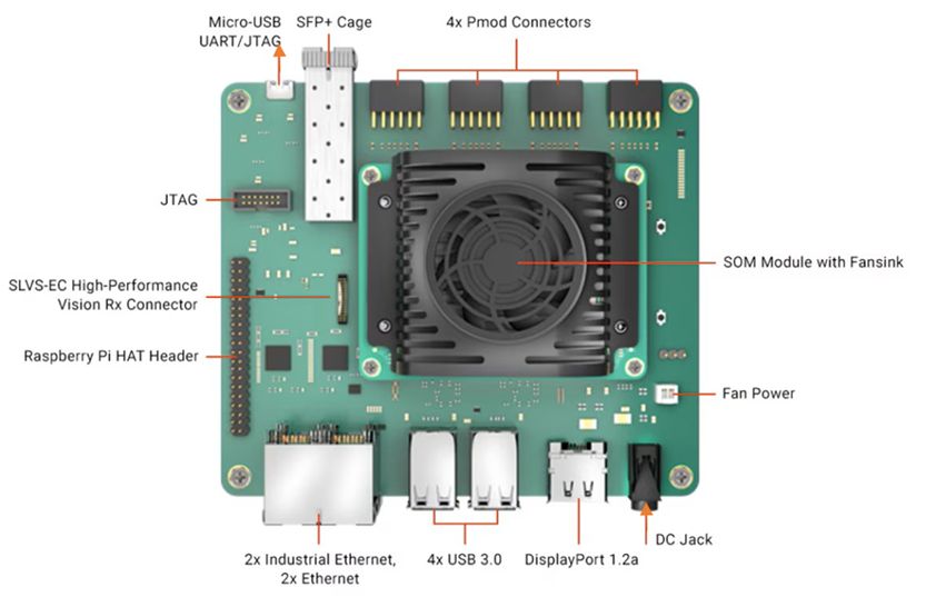
Figure 1‑1 AES256GCM10G25GIP demo environment on KR260 board
Linux OS setup (Ubuntu for KR260)
1) Follow the instructions on the AMD setup guide to download and prepare the SD card image. (https://www.amd.com/en/products/system-on-modules/kria/k26/kr260-robotics-starter-kit/getting-started/setting-up-the-sd-card-image.html).
2) After flashing image to SD card, user can see Linux file system as Figure 1‑2.
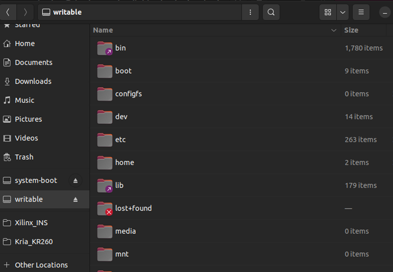
Figure 1‑2 Example of Linux file system on SD card
3) Copy folder “AES256GCM10G25GIP” from our demo package to “/lib/firmware/xilinx” on SD card.
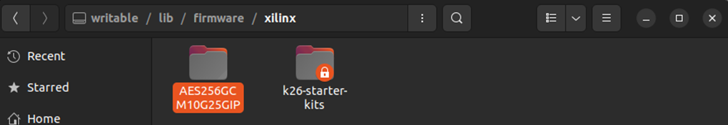
Figure 1‑3 "/lib/firmware/xilinx" directory on SD card
4) Copy software “AES256GCM10G25GDEMO” from our demo package to “/home” on SD card.
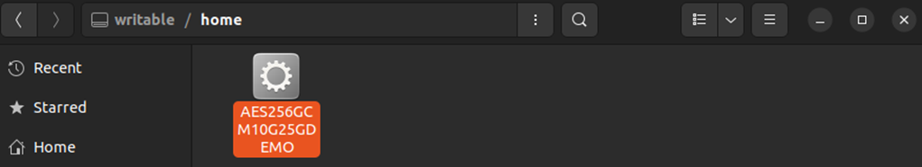
Figure 1‑4 "/home" directory on SD card
5) Remove SD card from PC, then insert SD card into the slot located under the KR260 board.
6) Connect the power supply to the FPGA development board. The board will automatically boot into Ubuntu as shown in Figure 1‑5.
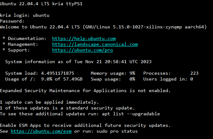
Figure 1‑5 KR260 board booting into Ubuntu
KR260 loadapp
To activate AES256GCM10G25G accelerator, if there is already another accelerator/firmware being activated, user must unload it first and then switch to AES256GCM10G25G accelerator as follows.
1) Unload the default hardware application using command below.
sudo xmutil unloadapp
2) Load new hardware application by using command below. The Figure 1‑6 shows example result for loading application on KR260 board.
sudo xmutil loadapp AES256GCM10G25GIP
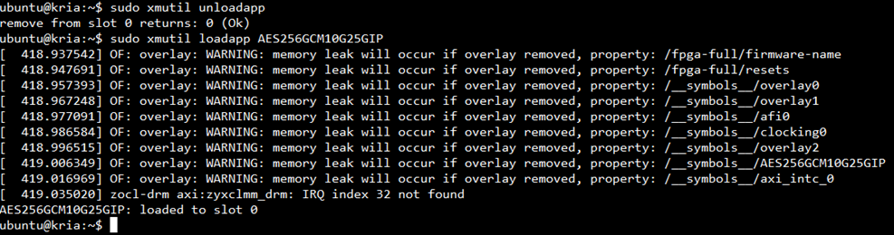
Figure 1‑6 Example result for loading application on KR260 board
2 AES256GCM10G25G Demo
To run the AES256GCM10G25GDEMO, use the command “sudo ./AES256GCM10G25GDEMO”. This will display the AES256GCM10G25G demo command menu as shown in Figure 2‑1. Through this menu, users can fill RAMs with additional authenticated data, plain or cipher data patterns, set encryption/decryption keys, initialize vectors (IV), and control test operations via the serial console. Detailed information on each menu is described in topic 3.
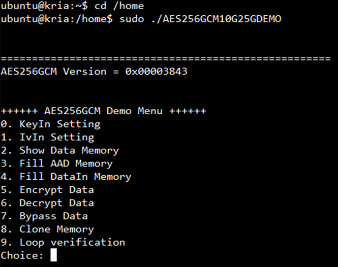
Figure 2‑1 Serial console
3 Command detail and testing result
3.1 KeyIn Setting
Step to set key as follows
a) Select “KeyIn Setting”.
b) Current key will be displayed on serial console as shown in Figure 3‑1.
c) Set new key: User is allowed to input new key in hex format or press “enter” to skip setting new key. Then the current key is printed again.
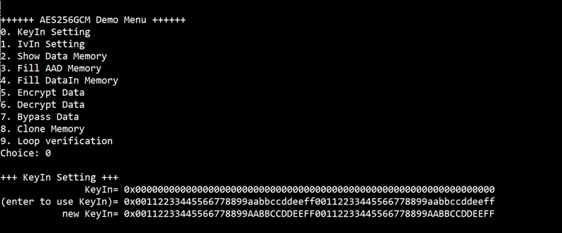
Figure 3‑1 KeyIn setting example
3.2 IvIn Setting
Step to set IV as follows
a) Select “IvIn Setting”.
b) Current IV will be displayed on serial console as shown in Figure 3‑2.
c) Set new IV: User is allowed to input new IV in hex format or press “enter” to skip setting new IV. Then the current IV is printed again.
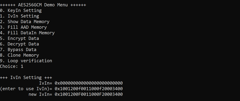
Figure 3‑2 IvIn setting example
3.3 Show Data Memory
To show data in memory, user can select “Show Data Memory”. User can input the desired length of data in byte to show. The data length will be aligned to 128 bits. DataIn and DataOut will be displayed in table-form as shown in Figure 3‑3. User can press “enter” to use 80 bytes as default value.
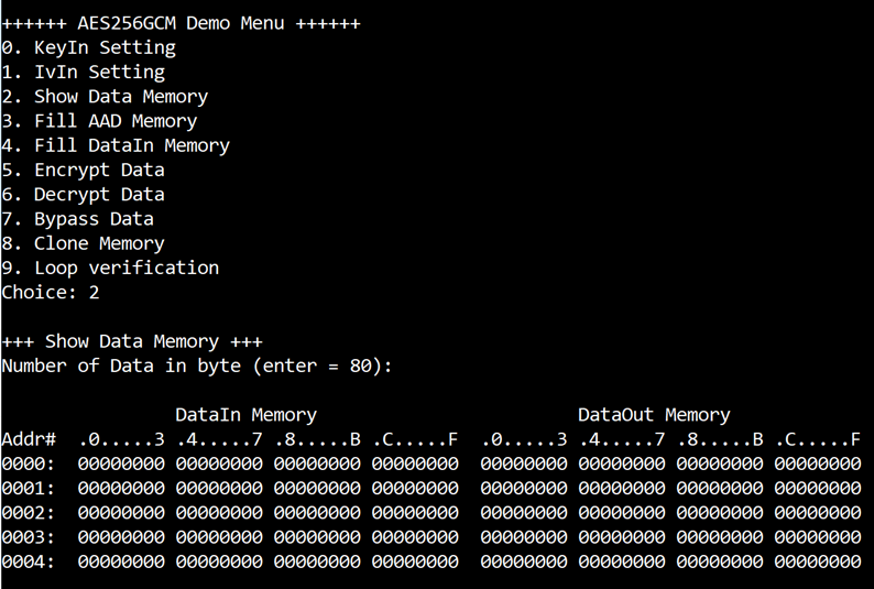
Figure 3‑3 Displayed data when input the desired length of data
3.4 Fill AAD Memory
Step to set AAD as follows
a) Select “Fill AAD Memory”.
b) Input the desired length of AAD in byte. In case of zero-length AAD operation, user can input “0” or press “enter” then end process of this menu. In case of non-zero-length AAD, user can select AAD pattern as shown in Figure 3‑4.
c) There are four pattern to fill AAD memory.
a. zero pattern
b. 8-bit counter
c. 16-bit counter
d. 32-bit counter
d) AAD memory will be filled with selected pattern by the number of AAD and zero-padding to become 128-bit padded data.
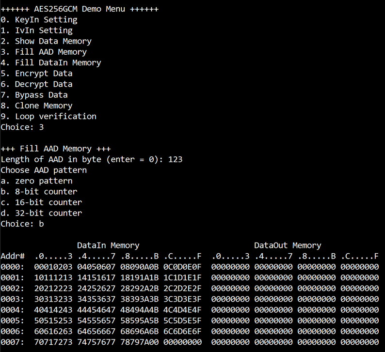
Figure 3‑4 Displayed data when set AAD pattern
3.5 Fill DataIn Memory
Step to fill DataIn in memory as follows
a) Select “Fill DataIn Memory”.
b) Input the desired length of data in byte. In case of zero-length DataIn operation, user can input “0” or press “enter” on keyboard then end process of this menu. In case of non-zero-length DataIn, user can select data pattern.
c) There are four pattern to fill memory.
a. zero pattern
b. 8-bit counter
c. 16-bit counter
d. 32-bit counter
d) Whole DataIn memory is filled with selected pattern after AAD according to the number of input data length as displayed in Figure 3‑5.
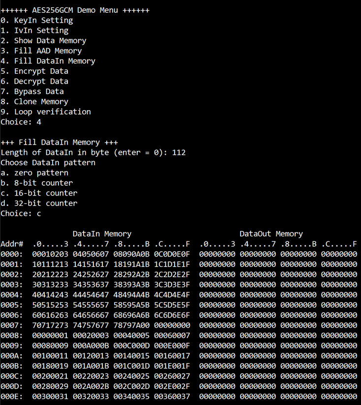
Figure 3‑5
Displayed data when set DataIn length and data pattern
3.6 Encrypt Data
Select “Encrypt Data” to encrypt DataIn in memory. Current length of AAD and length of DataIn are printed on serial console. When the encryption process is finished, both DataIn and DataOut will be displayed in table-form and 128-bit encryption tag will be printed as shown in Figure 3‑6.
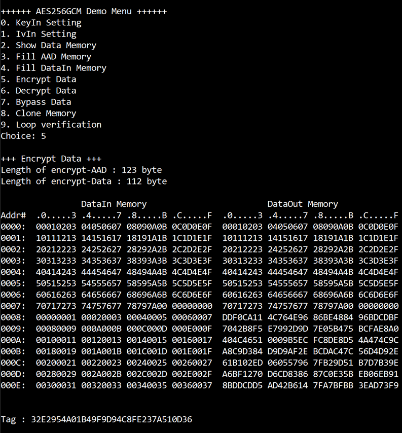
Figure 3‑6 Serial console after finished encryption process
3.7 Decrypt Data
Select “Decrypt Data” to decrypt DataIn in memory. Current length of AAD and length of DataIn are printed on serial console. When the decryption process is finished, both DataIn and DataOut will be displayed in table-form and 128-bit decryption tag will be printed as shown in Figure 3‑7.

Figure 3‑7 Serial console after finished decryption process
3.8 Bypass Data
Select “Bypass Data” to Bypass DataIn in memory. Current length of AAD and length of DataIn are printed on serial console. When the Bypass process is finished, both DataIn and DataOut will be displayed in table-form as shown in Figure 3‑8.
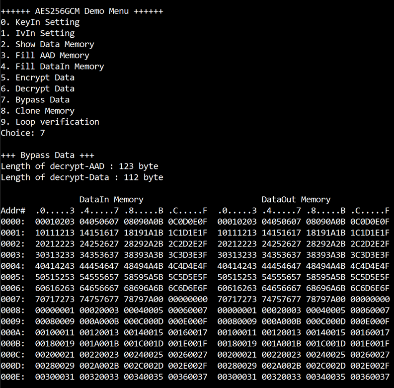
Figure 3‑8 Serial console after finished Bypass process
3.9 Clone Memory
Select “Clone Memory” for copy DataOut memory to DataIn memory. When the process is finished, both DataIn and DataOut will be displayed in table-form as shown in Figure 3‑9.
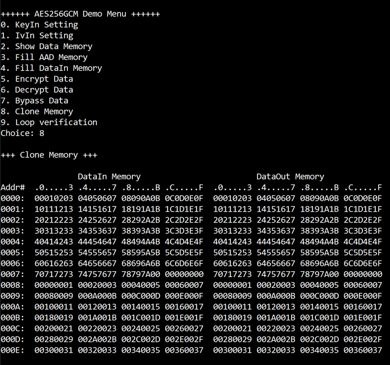
Figure 3‑9 Serial console after finished Clone Memory process
3.10 Loop verification
Select “Loop verification”, to check both encryption and decryption. In this menu, DataIn in memory will be encrypted/decrypted with all current parameters (key, IV, AAD and data in DataIn memory).
The function begins by read and store data from the DataIn memory as an original data and clear the DataOut memory before encryption, then start encryption process. After the encryption is completed, the data from the DataOut memory is cloned to the DataIn memory and decryption process is performed. Once the decryption is completed, the decrypted data is compared with the original data, and the encryption tag is compared with the decryption tag.
If the decrypted data and decryption tag match with original data and encryption tag, respectively, “Loop verification succeeded.” is printed as shown in Figure 3‑10.
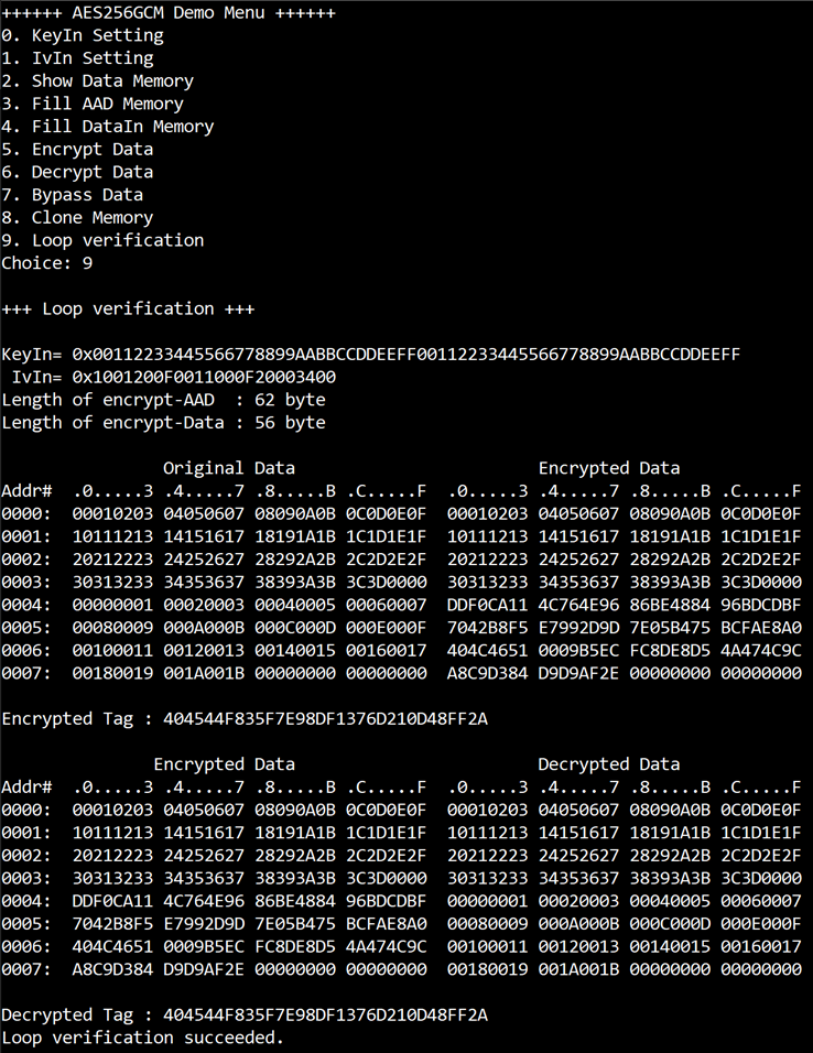
Figure 3‑10 Serial console after loop verification is succeeded
4 Revision History
|
Revision |
Date |
Description |
|
1.00 |
12-Jul-24 |
Initial version release |