AES256-XTS-STG IP Core Data Sheet
2. Encryption/Decryption control

Core Facts |
|
|
Provided with Core |
|
|
Documentation |
User Guide, Design Guide |
|
Design File Formats |
Encrypted File |
|
Instantiation Templates |
VHDL |
|
Reference Designs & Application Notes |
Quartus Project, See Reference Design Manual |
|
Additional Items |
Demo on A10SoC, Agilex7 I-Series development kit |
|
Support |
|
|
Support Provided by Design Gateway Co., Ltd. |
|
Design Gateway Co.,Ltd
E-mail: ip-sales@design-gateway.com
URL: design-gateway.com
Features
· Support AES-XTS mode standard.
· Support 256-bit key size.
· Support 128-bit IV size.
· Support auto increment IV every 512-byte Mode.
· Customized service for following features.
Modify block size for IV auto increment mode.
The products in this series
· AES256XTSSTG IP
Support data width 128-bit alignment.
Peak throughput rate at 128Mbits/MHz.
Speed up to 35.2 Gbps or 4.4 GBps @275MHz on A10SoC.
· AES256XTSSTG2X IP
Support data width 256-bit alignment.
Peak throughput rate at 256Mbits/MHz.
Speed up to 85.3 Gbps or 10.6 GBps @333.33MHz on Agilex7 F-Series.
· AES256XTSSTG4X IP
Support data width 512-bit alignment.
Peak throughput rate at 512Mbits/MHz.
Speed up to 204.8 Gbps or 25.6 GBps @400MHz on Agilex7 I-Series.
Table 1: Example Implementation Statistics for AES256XTS-STG
|
Family |
Example Device |
Type |
Fmax (MHz) |
ALMs |
Registers1 |
Design Tools |
|
Arria10 SX |
10AS066N3F40E2SGE2 |
ENC |
275 |
12701.1 |
5702 |
Quartus 20.4 |
|
DEC |
275 |
13689.1 |
6008 |
Quartus 20.4 |
||
|
Cyclone10 GX2 |
10CX220YF780E5G |
ENC |
280 |
12691.7 |
5639 |
Quartus 20.4 |
|
DEC |
280 |
13663.2 |
6019 |
Quartus 20.4 |
Table 2: Example Implementation Statistics for AES256XTS-STG-2X
|
Family |
Example Device |
Type |
Fmax (MHz) |
ALMs |
Registers1 |
Design Tools |
|
Agilex7 F-Series2 |
AGFB014R24A2E3VR0 |
ENC |
333.33 |
24604.0 |
13818 |
Quartus 20.4 |
|
DEC |
333.33 |
28248.4 |
23437 |
Quartus 20.4 |
Table 3: Example Implementation Statistics for AES256XTS-STG-4X
|
Family |
Example Device |
Type |
Fmax (MHz) |
ALMs |
Registers1 |
Design Tools |
|
Agilex7 I-Series |
AGIB027R29A1E2VR3 |
ENC |
400 |
50302.4 |
27476 |
Quartus 23.1 |
|
DEC |
400 |
56124.9 |
45084 |
Quartus 23.1 |
Notes:
1) Actual logic resource is dependent on percentage of unrelated logic.
2) The results were obtained from implementation in the same environment, but have not been tested on the actual board.
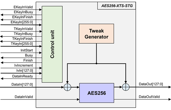
Figure 1: Block Diagram for AES256XTSSTGIP
General Description
AES256-XTS-STG IP Core (AES256XTSSTGIP) implement the advanced encryption standard (AES) with XEX (XOR Encrypt XOR) tweakable block cipher which operates sequences of complete blocks and is widely used in protecting the confidentiality of data on various storage devices with interfaces such as SATA and NVMe.
AES256XTSSTGIP works with 256-bit encryption key and 256-bit tweakable key. It supports 128-bit initialization vector (IV) which usually represents the Logical block addressing (LBA) of 512-byte block size. The encryption/decryption operates on 512-byte data block. After encrypting/decrypting each block of data, AES256XTSSTGIP recalculates a tweak value from the IV. When auto increment IV mode is enabled, the IV value will be increased by 1 for every block of encryption/decryption, ensuring a unique IV for each block and enhancing the security of the encryption/decryption process.
AES256XTSSTGIP(AES256XTS-StorageIP) Series consists of encryption module and decryption module, which each module contains of Tweak Generator and AES256 for encryption/decryption. The detailed of the products within the series is below.
AES256XTSSTGIP: This IP core includes the following modules:
· AES256XTSSTGENC is encrypted module designed for AES256XTSSTGIP.
· AES256XTSSTGDEC is decrypted module designed for AES256XTSSTGIP.
AES256XTSSTG2XIP: This IP core includes the following modules:
· AES256XTSSTG2XENC is encrypted module designed for AES256XTSSTG2XIP.
· AES256XTSSTG2XDEC is decrypted module designed for AES256XTSSTG2XIP.
AES256XTSSTG4XIP: This IP core includes the following modules:
· AES256XTSSTG4XENC is encrypted module designed for AES256XTSSTG4XIP.
· AES256XTSSTG4XDEC is decrypted module designed for AES256XTSSTG4XIP.
Functional Description
In the AES256XTSSTGIP Series encryption module and decryption module, the interface signals and operation are the same, therefore AES256XTSSTG is used to represent the interface signals and operation of both modules.
Table 4: Interface signals of AES256XTSSTG
|
Dir |
Description |
|
|
RstB |
In |
IP core system reset. Active low. |
|
Clk |
In |
IP core system clock. |
|
version[31:0] |
Out |
32-bit version number of AES256XTSSTG. |
|
Encryption Key setting signals |
||
|
EKeyInValid |
In |
EKeyInValid is a user signal to specify data valid of EKeyIn. Assert to ‘1’ to indicate that EKeyIn is valid and start encryption key setting. |
|
EKeyInBusy |
Out |
EKeyInBusy specifies busy status of encryption key setting. Assert to ‘1’ after user set EKeyInValid, until the last cycle of operation. EKeyInValid or InitStart will be ignored while EKeyInBusy is ‘1’. |
|
EKeyInFinish |
Out |
EKeyInFinish specifies finish status of encryption key setting. Assert to ‘1’ at the last cycle of operation. |
|
EKeyIn[255:0] |
In |
EKeyIn is 256-bit key data for encryption/decryption. EKeyIn must be valid when EKeyInValid is asserted to ‘1’. |
|
Tweakable Key setting signals |
||
|
TKeyInValid |
In |
TKeyInValid is a user signal to specify data valid of TKeyIn. Assert to ‘1’ to indicate that TKeyIn is valid and start tweakable key setting. |
|
TKeyInBusy |
Out |
TKeyInBusy specifies busy status of tweakable key setting. Assert to ‘1’ after user set TKeyInValid, until the last cycle of operation. TKeyInValid or InitStart will be ignored while TKeyInBusy is ‘1’. |
|
TKeyInFinish |
Out |
TKeyInFinish specifies finish status of tweakable setting. Assert to ‘1’ at the last cycle of operation. |
|
TKeyIn[255:0] |
In |
TKeyIn is 256-bit key data for encryption tweakable. TKeyIn must be valid when TKeyInValid is asserted to ‘1’. |
|
Encryption/Decryption control signals |
||
|
InitStart |
In |
InitStart is a user signal to start AES256XTSSTG operation. |
|
Busy |
Out |
Busy specifies busy status of operation. Busy is active after user set InitStart or DataInValid, until the last cycle of operation. EKeyInValid or TKeyInValid or InitStart will be ignored while Busy is ‘1’. |
|
Finish |
Out |
Finish specifies finish status of the last data calculation. After the user does not send DataInValid=‘1’ for 16 clock cycles Finish is asserted to ‘1’ at the last cycle of operation. |
|
IvIncrement |
In |
IvIncrement is a user signal to specify IV auto increment mode. This mode IV will increment by '1' for every 512-byte of data. IvIncrement must be valid when InitStart is asserted as '1'. |
|
IvIn[127:0] |
In |
IvIn is 128-bit IV data for generate tweak. IvIn must be valid when InitStart is asserted to ‘1’. |
Data control signals |
||
|
DataInReady |
Out |
DataInReady specifies that AES256XTSSTG is ready to receive data. DataInValid will be ignored while DataInReady is ‘0’. |
|
DataInValid |
In |
DataInValid is a user signal to specify data valid of DataIn. Assert to ‘1’ to indicate that DataIn is valid. |
|
DataIn[n-1:0] |
In |
DataIn is n-bit input data. DataIn must be valid when DataInValid is asserted to ‘1’. |
|
DataOutValid |
Out |
DataOutValid specifies data valid for DataOut. Assert to ‘1’ when DataOut is valid. |
|
DataOut[n-1:0] |
Out
|
DataOut is n-bit data output of AES256XTSSTG. Valid when DataOutValid is asserted to ‘1’. |
Note: n are integers representing the total data path width.
· n=128 for AES256XTSSTGIP
· n=256 for AES256XTSSTG2XIP
· n=512 for AES256XTSSTG4XIP
AES256XTSSTG operation is as simple as 2 steps to use as below.
1. Key setting
Key setting is the first step to use AES256XTSSTG. As shown in Figure 2. In the key setting process consists of encryption key setting and tweakable key setting, the two processes are completely independent of each other. AES256XTSSTG is started encryption key setting process when EKeyInValid=‘1’ and takes 14 clocks cycles to finish the process (EKeyInBusy=‘0’). After that, this EKeyIn is used for every encryption/decryption and can be changed via EKeyInValid is asserted to ‘1’. AES256XTSSTG is started tweakable key setting process when TKeyInValid=‘1’ and takes 14 clocks cycles to finish the process (TKeyInBusy=‘0’). After that, this TKeyIn is used for every encryption/decryption and can be changed via TKeyInValid is asserted to ‘1’.

Figure 2: AES256XTSSTG key setting timing diagram
2. Encryption/Decryption control
As shown in Figure 3 After Encryption key setting process and Tweak key setting process, AES256XTSSTG starts the process when InitStart is asserted to ‘1’ where IvIn and IvIncrement must be valid. Busy is set to be ‘1’ and DataInReady is cleared to ‘0’ in the next cycle. DataInReady signal is asserted to ‘1’ when the AES256XTSSTG is ready to receive incoming data. After that, AES256XTSSTG can operate data every clock cycle. The encryption/decryption process of the DataIn[n-1:0] data occurs when both the DataInValid signal and the DataInReady signal are asserted to '1'. Encrypted/Decrypted data is set to DataOut[n-1:0] signal, while the DataOutValid signal is set to be ‘1’. After the user does not send DataInValid=‘1’ for 16 clock cycles, Finish is active only one clock at the last cycle of operation and DataInBusy is cleared to ‘0’ in the next cycle.

Figure 3: Example of encryption/decryption timing diagram
If the user intends to modify the Initialization Vector (IV) value for every 512-byte block, user can set the IvIncrement to ‘1’ when initiating the process (InitStart=‘1’). The AES256XTSSTG encryption/decryption will automatically update the IV value by incrementing it by 1 for each 512-byte data segment transmitted by the user. It is important to note that the user is not required to set InitStart to ‘1’ to change the new IV value for uninterrupted data transfer in the case of continuous data.

Figure 4: Example of encryption/decryption in IV auto increment mode for AES256XTSSTGIP
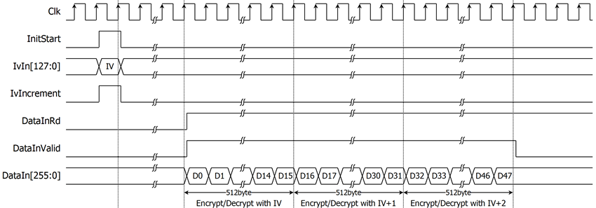
Figure 5: Example of encryption/decryption in IV auto increment mode for AES256XTSSTG2XIP
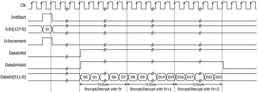
Figure 6: Example of encryption/decryption in IV auto increment mode for AES256XTSSTG4XIP
As shown in Figure 7, Busy signal will be cleared when the user does not send DataInValid=‘1’ more than 16 clock cycle, If the user wants to encrypted/decrypted with the same key and continuous IV as the previous operation, user can send DataInValid=‘1’ to encrypted/decrypted DataIn[n-1:0] without key setting. DataInReady signal will be cleared for initial new IV and IVIncrement mode when the user set InitStart=‘1’.

Figure 7: The timing diagram displays the pausing and continuing of the DataInvalid.
Verification Methods
AES256-XTS-STG IP Core functionality were verified on real board design by using Agilex7 I-Series development kit and Arria10 SoC development board.
Recommended Design Experience
The user must be familiar with HDL design methodology to integrate this IP into system.
Ordering Information
This product is available directly from Design Gateway Co., Ltd. Please contact Design Gateway Co., Ltd. For pricing and additional information about this product using the contact information on the front page of this datasheet.
Revision History
|
Revision |
Date |
Description |
|
1.00 |
11/Sep/2023 |
New release |