TOE10GLL-IP (Cut-through) 32-Session Demo Instruction
Rev1.0 30-Jun-23
3 Test result when using FPGA and TestPC
4 Test result when using two FPGAs
1 Overview
This document shows the example to run multi-session TOE10GLL-IP (Cut-through mode) demo with 32 instances by using two test environments. First is run by using one FPGA board transferring TCP data with TestPC which runs test applications for transferring TCP data via 10Gb. Test performance on the first environment is limited by the resource on TestPC. Second is run by using two FPGA boards for transferring 10Gb Ethernet data to each other. Using two FPGA boards including TOE10GLL-IP achieves the better performance for transferring TCP data via 10Gb Ethernet, comparing to the first environment.
In the document, topic 2 shows the example to set up 10Gb Ethernet card on TestPC to get the good performance for transferring data via 10Gb Ethernet when running the test by using the first test environment, FPGA and Test PC. Topic 3 shows the example console and test result when running under the first test environment. Finally, topic 4 shows the example console when running the second test environment, FPGA and FPGA. More details of each topic are described as follows.
Note:
1) To set up FPGA test environment, please follow the instruction described in FPGA set up for TOE/UDP10G-IP document (“dg_toeudp10gip_fpgasetup_xxx”).
2) This document shows the demo by using one target only; however, the user can set up the test environment by using two targets which may be all PCs, all FPGAs, or mixed PC and FPGA.
2 PC Setup
Before running demo, please check the network setting on PC. The example of setting 10Gb Ethernet card is described as follows.
2.1 IP Setting
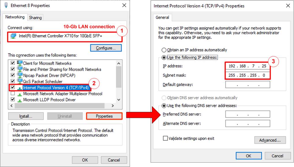
Figure 2‑1 Setting IP address for PC
1) Open Local Area Connection Properties of 10-Gb connection, as shown in the left window of Figure 2‑1.
2) Select “TCP/IPv4” and then click Properties.
3) Set IP address = 192.168.7.25 and Subnet mask = 255.255.255.0, as shown in the right window of Figure 2‑1.
2.2 Speed Setting

Figure 2‑2 Set Link Speed = 10 Gbps
1) On Local Area Connection Properties window, click “Configure” as shown in Figure 2‑2.
2) On Advanced Tab, select “Speed and Duplex”. Set the value to “10 Gbps Full Duplex” for running 10-Gigabit transfer test, as shown in Figure 2‑2
3) On “Interrupt Moderation” window, select “Disabled” to disable interrupt moderation which would minimize the latency during transferring data, as shown in Figure 2‑3.
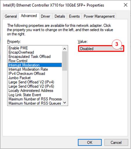
Figure 2‑3 Interrupt Moderation
4) On “Interrupt Moderation Rate” window, set value to “OFF”, as shown in Figure 2‑4.

Figure 2‑4 Interrupt Moderation Rate
5) Click “OK” button to save and exit all setting windows.
2.3 Power Option Setting
1) Open Control Panel and select Power Options as shown in the left window of Figure 2‑5.
2) Change setting to High Performance as shown in the right window of Figure 2‑5.
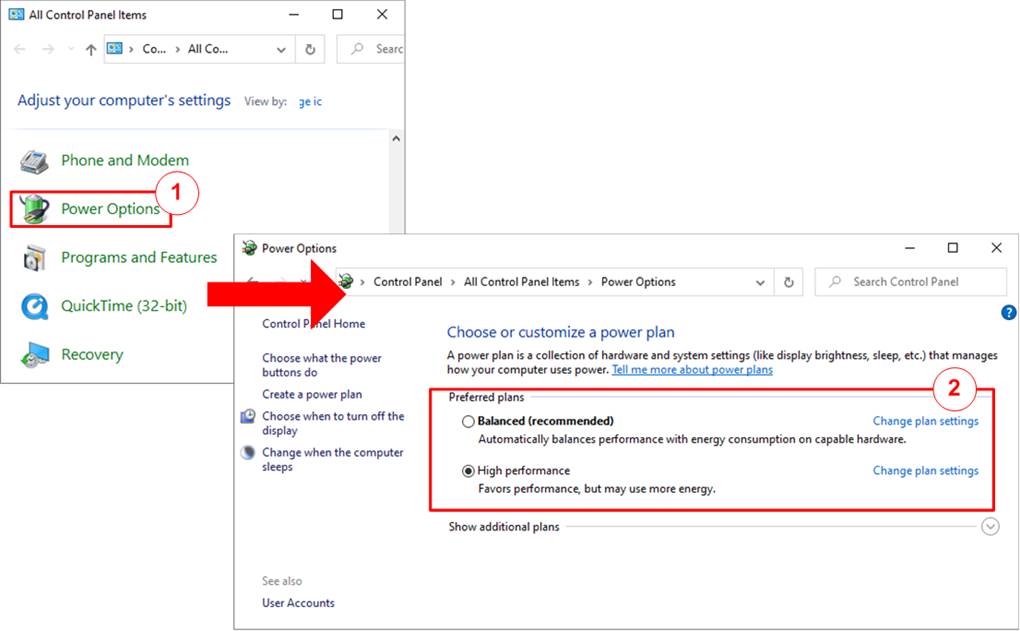
Figure 2‑5 Power options
3 Test result when using FPGA and TestPC
3.1 Display TCPIP parameters
Select ‘0’ to check current parameter in the demo. There are two groups of the parameters, i.e., common parameters which are shared for all session and target parameters which are set to each target individually. Typically, it is recommended to set initialization mode = “Client mode” for running FPGA and Test PC. Fixed-MAC mode can be run if the user knows the MAC address of Test PC.
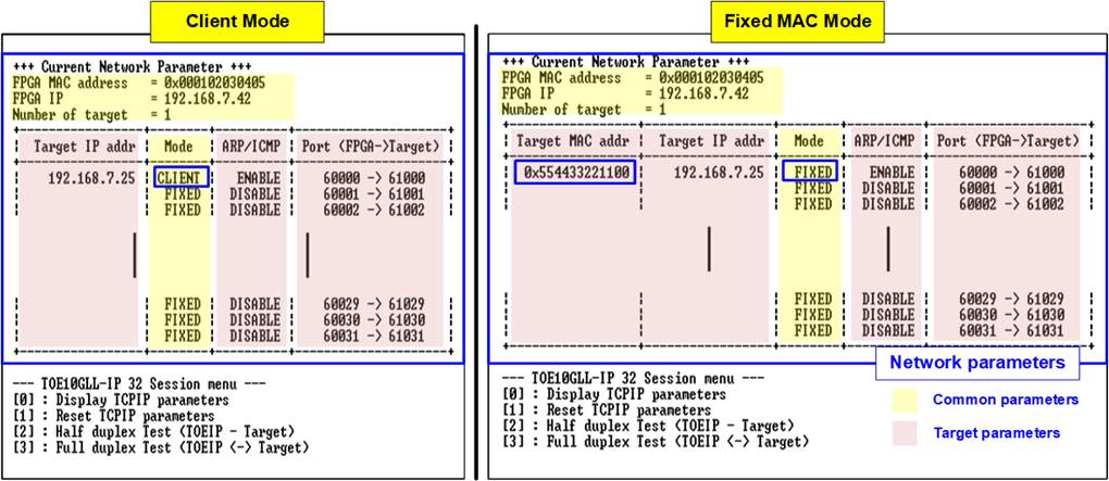
Figure 3‑1 Display current parameters
Most parameters of all sessions are listed in the table, except three parameters which shares the same value for all sessions.
1) FPGA MAC address: 48-bit hex value to be MAC address of FPGA. Default value is 0x000102030405.
2) FPGA IP: IP address of FPGA. Default value is 192.168.7.42.
Note: This value is used to be server IP address parameter for test application on PC.
3) Number of Target: Display total number of targets. Default value is 1.
The example shows the test with one target, so the same target parameters are assigned to all sessions, described as follows.
1) Target MAC address (displayed when running Fixed MAC mode only): 48-bit hex value to be MAC address of the target device. Default value is 0x554433221100.
2) Target IP address: IP address of the target device (10 Gb Ethernet on PC). Default value is 192.168.7.25.
The unique parameters that are assigned for each session are port numbers. FPGA port number is shown in the left-hand side while Target port number is shown in the right-hand side. Only the first session of each target can be assigned while the other sessions are calculated by using incremental pattern.
1) FPGA port number: The port number of FPGA. Default value of the first session is 60000.
Note: Port number of FPGA is used to be server port for test application on PC.
2) Target port number: The port number of target. Default value of the first session is 61000.
The table also shows the two additional parameters – Initialization mode and ARP/ICMP enable.
1) The initialization mode: User sets the initialization mode of the first session for all target to be ‘0’ (Client), ‘1’ (Server), or ‘2’) (Fixed-MAC). To run with PC, please input ‘0’ to initialize the IP in client mode. The other sessions are fixed to Fixed-MAC mode.
2) ARP/ICMP enable: User sets this flag to the first session of each target individually. Default value is Enable. The other sessions are fixed to Disable. When this feature is enabled, TOE10GLL-IP generates ARP reply packet or ICMP Echo reply packet when ARP request packet or ICMP Echo request packet is received.
To change some parameters, user can set by using menu [1] (Reset TCPIP parameters).
3.2 Reset TCPIP parameters
Select ‘1’ to reset the IP and change IP parameters.
This menu is run to reset the IP with or without updating parameters. After selecting this menu, the current parameters are displayed on the console. User enters ‘x’ to use the current value or enters other keys to change some parameters. After the parameters are set, all TOE10GLL-IPs are reset and start the initialization process.
The description of each parameter is shown in topic 3.1 (Display TCPIP parameter). The menu to set each parameter are split to two phases. First is the common parameter that share to all session. Second is the target parameter that is assigned each target individually. The range of each parameter is described as follows.
Common parameters
1) Mode: Input ‘0’, ‘1’, or ‘2’ to initialize the IP in Client mode, Server mode, or Fixed-MAC mode, respectively.
Note: When TestPC and FPGA are connected in different network which cannot communicate by ARP process, it needs to run TOE10GLL-IP in Fixed MAC mode to set MAC address manually via the console instead of using ARP process.
2) FPGA MAC address: Input 12 digits of hex value. Add “0x” as a prefix to input as hex value.
3) FPGA IP address: A set of four decimal digits is separated by “.”. The valid range of each decimal digit is 0-255.
4) Number of targets: The total number of targets in the test system. Valid range is 1-2. (The variable in this demo supports up to 2 targets).
Target parameters
1) ARP/ICMP enable: Set ‘1’ to enable ARP/ICMP reply for the first session in each target. If set ‘0’, ARP reply and ICMP Echo reply will not be returned by TOE10GLL-IP.
2) Target MAC address (displayed when running Fixed MAC mode only): Input 12 digits of hex value. Add “0x” as a prefix to input as hex value.
3) Target IP address: A set of four decimal digits, similar to FPGA IP address. This value is IP address of Test PC.
4) Start FPGA port number: The FPGA port number of the first session in this target. Valid range is 0-65504. When the first port is 65504, the other sessions are assigned by incremental value (65505, 65506, …, 65535).
5) Start Target port number: The target port number of the first session in this target. Valid range is 0-65504. When the first port is 65504, the other sessions are assigned by incremental value (65505, 65506, …, 65535).
6) Number of sessions: The total number of TCPIP session in this target device. Valid range depends on the number of targets. For one target device system, the number of sessions can be set to 1 - 32.
After finishing parameter assignment, the updated parameters are displayed on the console. Next, the reset signal is sent to all IPs to initialize the IPs by using new parameters. Finally, “IP initialization complete” is shown after the IPs complete initialization process, as shown in Figure 3‑2.

Figure 3‑2 Change IP parameter
3.3 Half-duplex Test
To transfer data in single direction, select ‘2’ to run half-duplex test on FPGA and run “tcpdatatest.exe” on PC to send or receive data. The half-duplex test allows user to disable or enable to send/receive data of each target individually. All sessions in the same target device shares the same test parameters. User sets three values for each target, i.e., ‘0’-No operation, ‘1’-Send test, and ‘2’-Receive test. The details when running by Send test and Receive test are shown as below.
3.3.1 Send Test
When Send test is selected, PC must run “tcpdatatest” to receive the data by using the recommend parameters for each session. The sequence to run Send test is shown as follows.
1) On FPGA console, input test parameters of each target.
a) Input test mode: ‘0’-Disable and skip to assign the next target, ‘1’-Send test.
b) Input test sessions: Number of sessions that will be tested. Valid range is 1 to number of sessions in this target.
c) Input transfer size: Unit of transfer size is byte. Valid value is 1 - 0xFFFF_FFFF_FFFF. The input is decimal unit when input only digit number. User adds “0x” to be a prefix for hexadecimal unit.
d) Input packet size: Unit of packet size is byte. Valid value is 1 – 1460. The input is decimal unit when input only digit number. User adds “0x” to be a prefix for hexadecimal unit.
e) Enable PSH: TCP flag to inform that the target device should return acknowledgement packet for the latest transmitted data immediately. Input ‘0’ to disable PSH flag or ‘1’ to enable PSH flag.
f) Input Mode: Open connection mode. Input ‘1’ to set Server mode.
The input assignment is repeated until all targets are assigned.
2) If all inputs are valid, the recommended parameters to run test application on PC are displayed. Next, the IP address of the active target is displayed. After that, “Wait connection” is displayed to wait until the application is run on PC.
3) On PC, open Command prompt window for running the recommended command from FPGA console. The number of command prompt windows that must be run is equal to the number of test sessions set in step 1b). User runs test application by using the recommended value. There are six parameters for running “tcpdatatest” to receive data.
>> tcpdatatest <mode> <dir> <server IP> <server port> <bytelen> <pattern>
a) Mode: Input ‘c’ to run Test PC as a client.
b) Dir: Input ‘r’ to run Test PC for receiving and verifying test data from FPGA
c) Server IP: Input the same value as IP address of FPGA
d) Server port: Input the same value as port number of FPGA on the selected session
e) Bytelen: Input the same value as “Input transfer size” of step 1c) on the selected session
f) Pattern: Input ‘1’ to verify data from FPGA or ‘0’ to not verify data
4) After running the test application, the port is created. Current amount of transferred data is displayed on the console (transmitted data) and Command prompt (received data) every second. The console on FPGA shows total amount of transmitted data in each target while the console on PC shows the amount of received data in each session.
5) “Half-duplex test complete” is displayed after all connections are closed. Finally, total amount of transferred data and performance in each target are displayed on FPGA console. While Command prompt displays total amount of data and performance in each session.
Figure 3‑3 shows the example of one-session send test when using 1460-byte packet size with enabling data verification on test application. The left window is FPGA console operating as Server and the right window is Command prompt on PC operating as Client.
Note: The transmitted performance of one session in multi-session demo (485 MB/s) is less than the performance of one-session demo (1143 MB/s) because Tx buffer size configured in TOE10GLL-IP of multisession demo is equal to 8 Kbyte instead of 64 Kbyte.

Figure 3‑3 One-session Send test for by using 1460-byte packet size
Figure 3‑4 shows the example of four-session send test when using 1460-byte packet size with enabling data verification on test application. Comparing with one-session test, as shown in Figure 3‑3, the performance of total session is almost equal to 10Gb Ethernet bandwidth while the individual performance of each session is about (total performance/4).
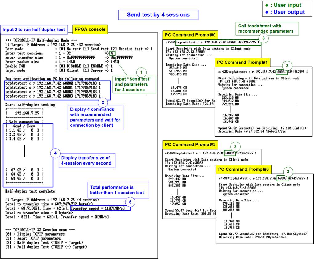
Figure 3‑4 Four-session Send test for by using 1460-byte packet size
Figure 3‑5 shows the example of Thirty-two-session send data test which is the maximum number of sessions in this demo. The total performance of running Thirty-two-session test is slightly improved from the performance of running four-session test.
Note: Please be concerned about transfer size when running 32 sessions. Total transfer size is equal to this value x 32. For example, when setting 0xFFFF_FFFF (4GB), total transfer size is equal to 128 GB (4GB x 32).
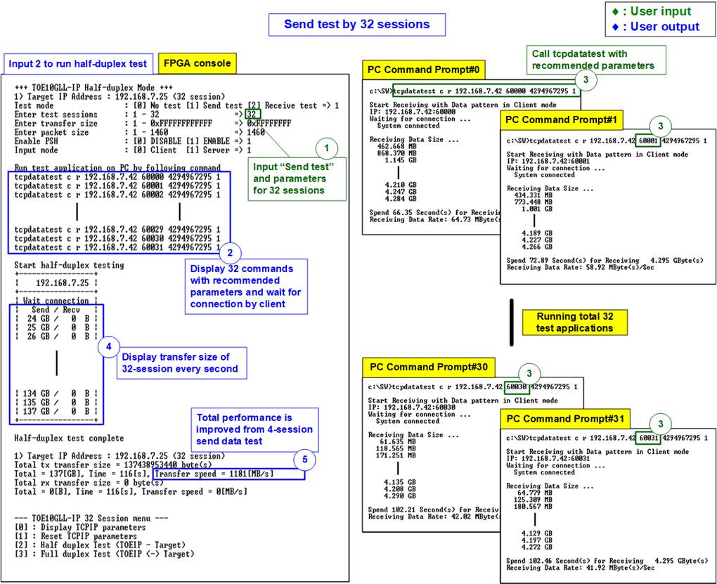
Figure 3‑5 Thirty-two-session Send test for by using 1460-byte packet size
If some inputs are invalid, error message is displayed. After that, the operation is cancelled, as shown in Figure 3‑6 - Figure 3‑9.
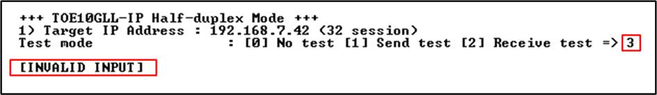
Figure 3‑6 Error from invalid test mode
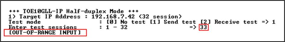
Figure 3‑7 Error from invalid test sessions
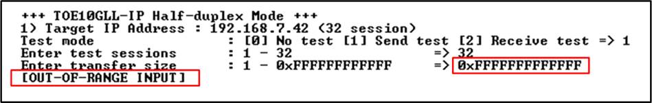
Figure 3‑8 Error from invalid transfer size
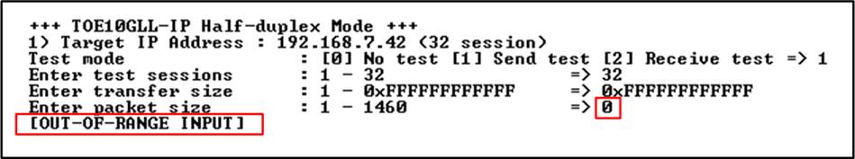
Figure 3‑9 Error from invalid packet size
3.3.2 Receive Test
When Receive test is selected, PC must run “tcpdatatest” to send the data by using the recommend parameters for each session. The sequence to run Receive test is shown as follows.
1) On FPGA console, input test parameters of each target.
a) Input test mode: ‘0’-Disable and skip to assign the next target, ‘2’-Receive test.
b) Input test sessions: Number of sessions that will be tested. Valid range is 1 to number of sessions in this target.
c) Input transfer size: Unit of transfer size is byte. Valid value is 1 - 0xFFFF_FFFF_FFFF. The input is decimal unit when input only digit number. User adds “0x” to be a prefix for hexadecimal unit.
d) Input data verification mode: ‘0’-disable data verification, ‘1’-enable data verification.
e) Input Mode: Open connection mode. Input ‘1’ to set Server mode.
The input assignment is repeated until all targets are assigned.
2) If all inputs are valid, the recommended parameters to run test application on PC are displayed. Next, the IP address of the active target is displayed. After that, “Wait connection” is displayed to wait until the application is run on PC.
3) On PC, open Command prompt window for running the recommended command from FPGA console. The number of command prompt windows that must be run is equal to the number of test sessions set in step 1b). User runs test application by using the recommended value. There are six parameters for running “tcpdatatest” to send data.
>> tcpdatatest <mode> <dir> <server IP> <server port> <bytelen> <pattern>
a) Mode: Input ‘c’ to run Test PC as a client.
b) Dir: Input ‘t’ to run Test PC for sending test data to FPGA
c) Server IP: Input the same value as IP address of FPGA
d) Server port: Input the same value as port number of FPGA on the selected session
e) Bytelen: Input the same value as “Input transfer size” of step 1c) on the selected session
f) Pattern: Input the same value as “Input data verification mode” of step 1d) on the selected session. ‘0’-Send dummy data, ‘1’-Send incremental data.
4) After running the test application, the port is created. Current amount of transferred data is displayed on the console (received data) and Command prompt (transmitted data) every second. The console on FPGA shows total amount of received data in each target while the console on PC shows the amount of transmitted data in each session.
5) “Half-duplex test complete” is displayed after all connections are closed. Finally, total amount of transferred data and performance in each target are displayed on FPGA console. While Command prompt displays total amount of data and performance in each session.
Figure 3‑10 shows the example of one-session receive test when data verification mode on FPGA is enabled and incremental data is sent by PC. The left window is FPGA console operating as Server and the right window is Command prompt window on PC operating as Client.

Figure 3‑10 One-session receive test
Figure 3‑11 shows the example of four-session receive test when data verification mode on FPGA is enabled and incremental data is sent by PC. Comparing to Figure 3‑10, the total performance in this test environment is better than using only one session.

Figure 3‑11 Four-session receive test
Figure 3‑12 shows the example of using maximum number of sessions running receive data test which is 32 sessions. Other test parameters in this environment are the same as one-session and four-session receive data test. The total performance of running Thirty-two-session test is similar to the performance of running four-session test.
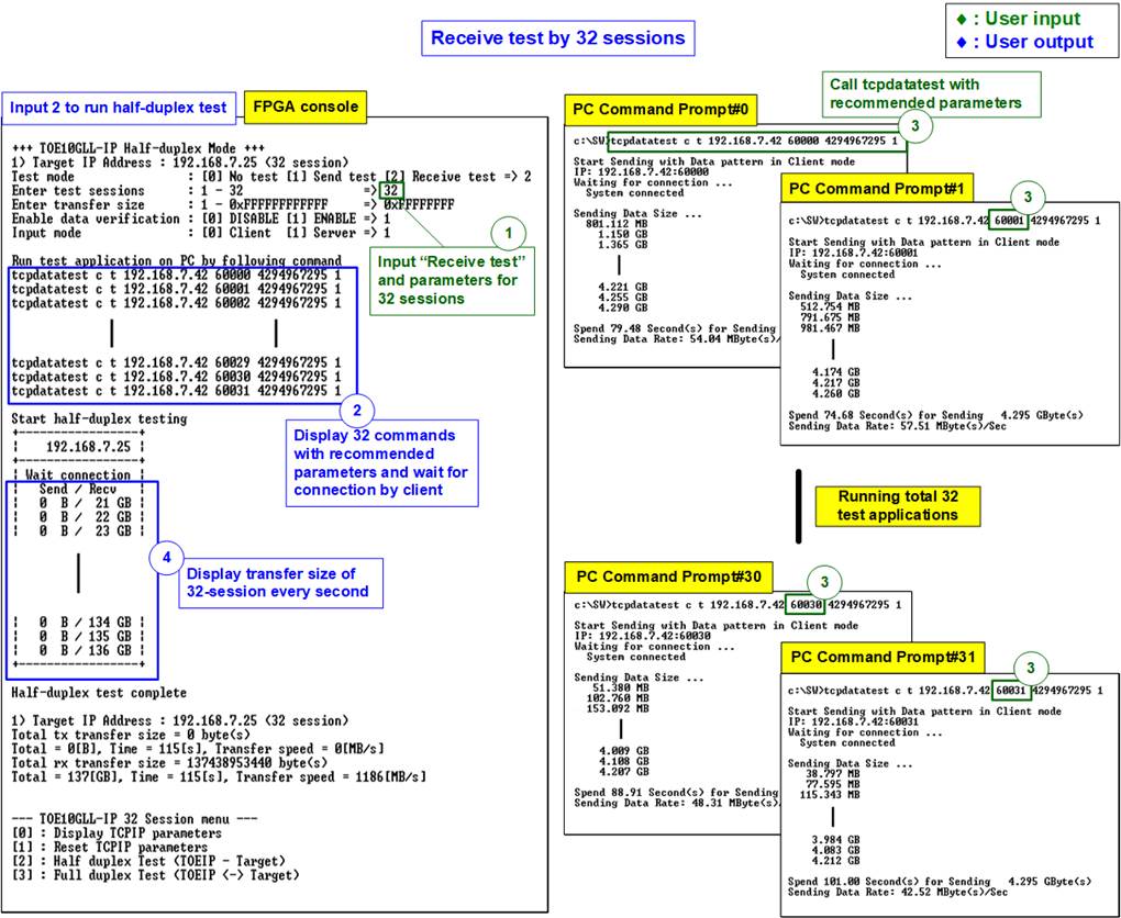
Figure 3‑12 Thirty-two-session receive test
3.4 Full duplex Test
Select ‘3’ to run full duplex test to transfer data between FPGA and PC in both directions. After that, user assigns test parameters of each target individually on FPGA console. Also, user can enable or disable each target. On TestPC, Command prompts is opened to run “tcp_client_txrx_single” application. Multiple applications are run to support multi-session test. The sequence to run the test is shown as below.
1) On FPGA console, input test parameters of each session.
a) Input test mode: ‘0’-Disable and skip to assign the next target, ‘1’-Full duplex test.
b) Input test sessions: Number of sessions that will be tested. Valid range is 1 to number of sessions in this target.
c) Input transfer size: Unit of transfer size is byte. Valid value is 1 - 0xFFFF_FFFF_FFFF. The input is decimal unit when input only digit number. User adds “0x” to be a prefix for hexadecimal unit.
d) Input packet size: Unit of packet size is byte. Valid value is 1 – 1460. The input is decimal unit when input only digit number. User adds “0x” to be a prefix for hexadecimal unit.
e) Enable PSH: TCP flag to inform that the target device should return acknowledgement packet for the latest transmitted data immediately. Input ‘0’ to disable PSH flag or ‘1’ to enable PSH flag.
f) Input data verification mode: ‘0’-disable data verification, ‘1’-enable data verification.
g) Input Mode: Open connection mode. Input ‘1’ to set Server mode.
The input assignment is repeated until all targets are assigned.
2) If all inputs are valid, the recommended parameters to run test application on PC are displayed. Next, the IP address of the active target is displayed. After that, “Wait connection” is displayed to wait until the application is run on PC.
3) On PC, open Command prompt window for running the recommended command from FPGA console. The number of command prompt windows that must be run is equal to the number of test sessions set in step 1b). User runs test application by using the recommended value. There are four parameters for running “tcp_client_txrx_single”.
>> tcp_client_txrx_single <server IP> <server port> <bytelen> <pattern>
a) Server IP: Input the same value as IP address of FPGA
b) Server port: Input the same value as port number of FPGA on the selected session
c) ByteLen: Total transfer size in byte unit. Input the same value as “Input transfer size” of step 1c) on the selected target.
d) Pattern: ‘0’ - Send dummy data and disable data verification. ‘1’ - Send incremental data and enable data verification. Input the same value as “Input data verification mode” of step 1f) on the selected target.
4) After running the test application, the port is created. Current amount of transferred data for both transmit side and receive side is displayed on the console and Command prompt every second. The console on FPGA shows total amount of transferred data in each target while the console on PC shows the amount of transmitted data in each session.
5) “Full-duplex test complete” is displayed after all connections are closed. Finally, total amount of transferred data and performance in each target are displayed on FPGA console. While Command prompt displays total amount of data and performance in each session.
Figure 3‑13 shows the example of running four-session full duplex test when data verification mode on FPGA/PC is enabled and incremental data are sent from both FPGA and PC. The left window is FPGA console operating as Server and the right window is four Command prompt windows on PC operating as Client.

Figure 3‑13 Four-session Full duplex test
As shown in Figure 3‑13, the performance of running four-session full duplex test does not achieve the best performance because of the small transmit buffer size in TOE10GLL-IP and the high work load of CPU when running many applications.
3.5 Ping Test
For Ping command test, use can type “ping <FPGA IP address>” command on Command prompt to start the test. ICMP Echo request is generated from PC and then FPGA returns ICMP Echo reply to PC. Finally, the result to show round-trip time is displayed on Command prompt, as shown in Figure 3‑14.

Figure 3‑14 Ping command result on PC
4 Test result when using two FPGAs
4.1 Display TCPIP parameter
Select ‘0’ to check current parameter in the demo. There are two groups of the parameters, i.e., common parameters which are shared for all session and target parameters which are set to each target individually.
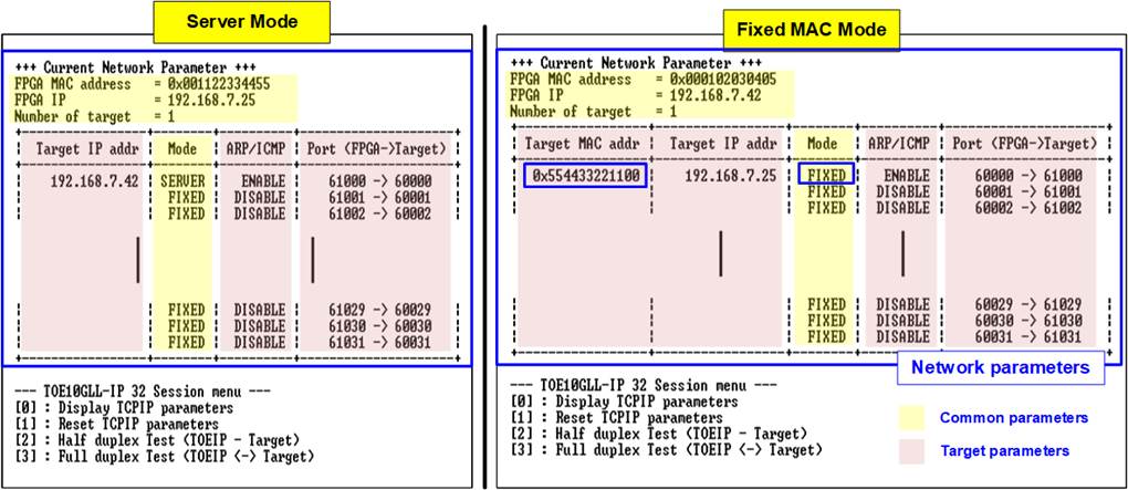
Figure 4‑1 Display current parameters
Most parameters of all sessions are listed in the table, except three parameters which shares the same value for all sessions.
1) FPGA MAC address: 48-bit hex value to be MAC address of FPGA. Default value is 0x000102030405 (Client/Fixed-MAC mode) or 0x001122334455 (Server mode).
2) FPGA IP: IP address of FPGA. Default value is 192.168.7.42 (Client/Fixed-MAC mode) or 192.168.7.25 (Server mode).
3) Number of Target: Display total number of targets. Default value is 1.
The example shows the test with one target, so the same target parameters are assigned to all sessions, described as follows.
1) Target MAC address (displayed when running Fixed MAC mode only): 48-bit hex value to be MAC address of the target device. Default value is 0x554433221100.
2) Target IP address: IP address of the target device (10 Gb Ethernet on PC). Default value is 192.168.7.25 (Client/Fixed-MAC mode) or 192.168.7.42 (Server mode).
The unique parameters that are assigned for each session are port numbers. FPGA port number is shown in the left-hand side while Target port number is shown in the right-hand side. Only the first session of each target can be assigned while the other sessions are calculated by using incremental pattern.
1) FPGA port number: The port number of FPGA. Default value of the first session is 60000 (Client/Fixed-MAC mode) or 61000 (Server mode).
2) Target port number: The port number of target. Default value of the first session is 61000 Client/Fixed-MAC mode) or 60000 (Server mode).
The table also shows the two additional parameters – Initialization mode and ARP/ICMP enable.
1) The initialization mode: User sets the initialization mode of the first session for all target to be ‘0’ (Client), ‘1’ (Server), or ‘2’) (Fixed-MAC).
2) ARP/ICMP enable: User sets this flag to the first session of each target individually. Default value is Enable. The other sessions are fixed to Disable. When this feature is enabled, TOE10GLL-IP generates ARP reply packet or ICMP Echo reply packet when ARP request packet or ICMP Echo request packet is received.
To change some parameters, user can set by using menu [1] (Reset TCPIP parameters).
4.2 Reset TCPIP parameters
Select ‘1’ to reset the IP and change IP parameters.
This menu is used to reset the IP with or without updating parameters. After selecting this menu, the current parameters are displayed on the console. User enters ‘x’ to use the current value or enters other keys to change parameters. After the parameters are set, all TOE10GLL-IPs are reset and start the initialization process.
The description of each parameter is shown in topic 4.1 (Display TCPIP parameter). The menu to set each parameter are split to two phases. First is the common parameter that share to all session. Second is the target parameter that is assigned each target individually. The range of each parameter is described as follows.
Note: When running the test by using FPGA – FPGA communication, please refer following rules.
1. The mode on two FPGAs must be set to Server – Client, Client – Fixed MAC, or Fixed MAC – Fixed MAC.
2. When running Server – Client mode and user needs to reset parameters on the Server FPGA, the Client FPGA must be also reset. Also, the Server must be reset before the Client to wait until ARP request sent by the Client.
3. Parameter of two FPGAs must be matched as follows.
a. Target IP of board#1 = FPGA IP of board#2
b. FPGA IP of board#1 = Target IP of board#2
c. Start Target port number of board#1 = Start FPGA port number of board#2
d. Start FPGA port number of board#1 = Start Target port number of board#2
Common parameters
1) Mode: Input ‘0’, ‘1’, or ‘2’ to initialize the IP in Client mode, Server mode, or Fixed-MAC mode, respectively.
2) FPGA MAC address: Input 12 digits of hex value. Add “0x” as a prefix to input as hex value.
3) FPGA IP address: A set of four decimal digits is separated by “.”. The valid range of each decimal digit is 0-255.
4) Number of targets: The total number of targets in the test system. Valid range is 1-2. (The variable in this demo supports up to 2 targets).
Target parameters
1) ARP/ICMP enable: Set ‘1’ to enable ARP/ICMP reply for the first session in each target. If set ‘0’, ARP reply and ICMP Echo reply will not be returned by TOE10GLL-IP.
2) Target MAC address (displayed when running Fixed MAC mode only): Input 12 digits of hex value. Add “0x” as a prefix to input as hex value.
3) Target IP address: A set of four decimal digits, similar to FPGA IP address. This value is IP address of Test PC.
4) Start FPGA port number: The FPGA port number of the first session in this target. Valid range is 0-65504. When the first port is 65504, the other sessions are assigned by incremental value (65505, 65506, …, 65535).
5) Start Target port number: The target port number of the first session in this target. Valid range is 0-65504. When the first port is 65504, the other sessions are assigned by incremental value (65505, 65506, …, 65535).
6) Number of sessions: The total number of TCPIP session in this target device. Valid range depends on the number of targets. For one target device system, the number of sessions can be set to 1 - 32.
After finishing parameter assignment, the updated parameters are displayed on the console. Next, the reset signal is sent to all IPs to initialize the IPs by using new parameters. Finally, “IP initialization complete” is shown after the IPs complete initialization process, as shown in Figure 4‑2 and Figure 4‑3.
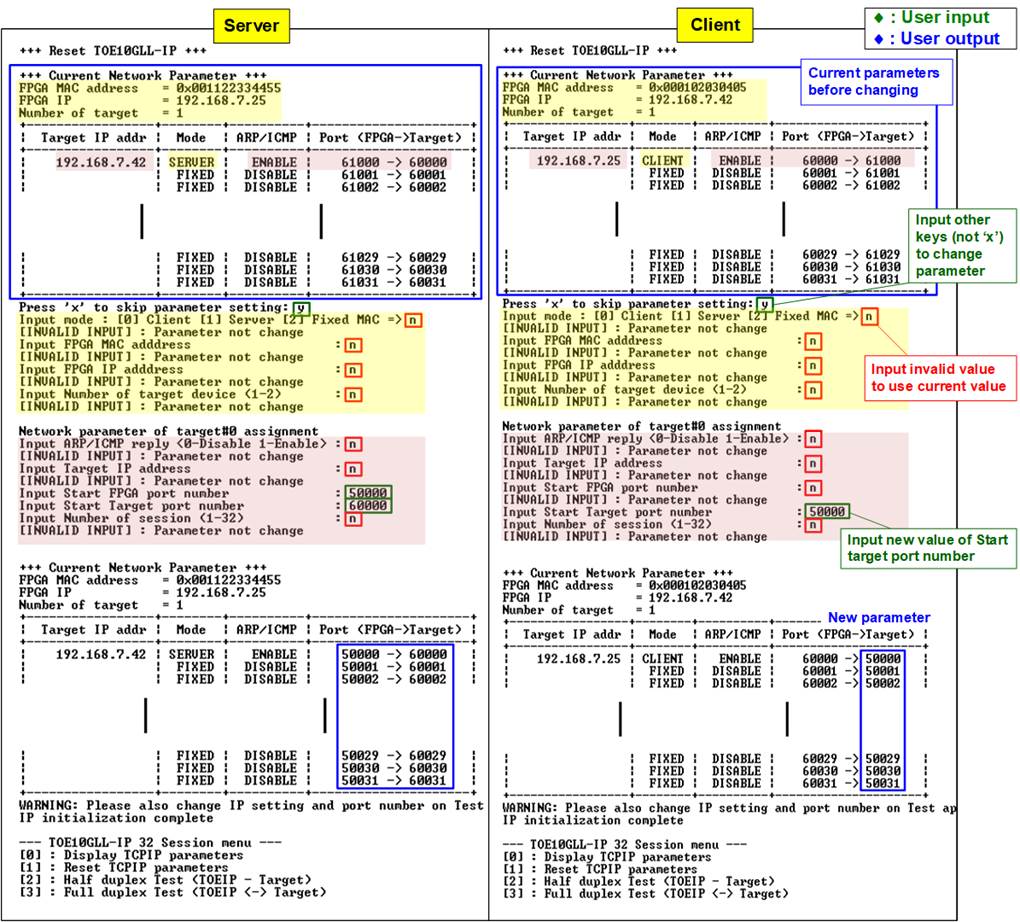
Figure 4‑2 Change IP parameters when running Server and Client mode
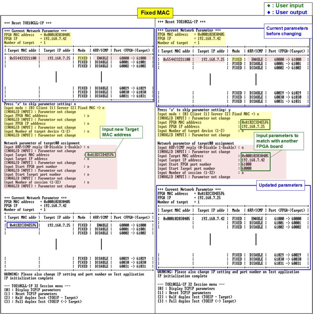
Figure 4‑3 Change IP parameters when running Fixed MAC mode
4.3 Half-duplex Test
To transfer data in single direction between two FPGAs, select ‘2’ to run half-duplex test on the FPGA@board1 and FPGA@board2 for running send test and receive test, respectively. The half-duplex test allows user to assign test parameters on console for each target separately. The sequence to run the test when Server runs Send test and Client runs Receive test is shown as follows.
Note: The mode set in half-duplex test to open the connection is assigned. The end-point as Client creates the connection while the end-point as Server waits for connection. However, the close connection is applied by test mode, either send or receive test. The send end-point is the one that closes the connection as Client. It does not relate to the initialization mode which is set to be Client, Server, or Fixed-MAC mode.
1) On FPGA@board1 console which runs Send test, input test parameters under half-duplex test menu.
a) Input test mode: ‘0’-Disable and skip to assign the next target, ‘1’-Send test.
b) Input test sessions: Number of sessions that will be tested. Valid range is 1 to number of sessions in this target.
c) Input transfer size: Unit of transfer size is byte. Valid value is 1 - 0xFFFF_FFFF_FFFF. The input is decimal unit when input only digit number. User adds “0x” to be a prefix for hexadecimal unit.
d) Input packet size: Unit of packet size is byte. Valid value is 1 – 1460. The input is decimal unit when input only digit number. User adds “0x” to be a prefix for hexadecimal unit.
e) Enable PSH: TCP flag to inform that the target device should return acknowledgement packet for the latest transmitted data immediately. Input ‘0’ to disable PSH flag or ‘1’ to enable PSH flag.
f) Input Mode: Open connection mode. Input ‘1’ to set Server mode.
The input assignment is repeated until all targets are assigned.
2) If all inputs on FPGA@board1 console are valid, the parameter of the active target is displayed. “Wait connection” is displayed to wait until Client (FPGA@board2) sends request for the new connection.
3) On FPGA@board2 console which runs receive test, input test parameters under half-duplex test menu.
a) Input test mode: ‘0’-Disable and skip to assign the next target, ‘2’-Receive test.
b) Input test sessions: Number of sessions that will be tested. Valid range is 1 to number of sessions in this target. This value must be equal to number of test sessions in step 1b).
c) Input transfer size: Unit of transfer size is byte. Valid value is 1 - 0xFFFF_FFFF_FFFF. The input is decimal unit when input only digit number. User adds “0x” to be a prefix for hexadecimal unit. This value must be equal to total transfer size in step 1c).
d) Input data verification mode: Input ‘1’ to enable data verification sent from FPGA@board1.
e) Input Mode: Open connection mode. Input ‘0’ to transfer as Client mode.
The input assignment is repeated until all targets are assigned.
4) If all inputs on FPGA@board2 console are valid, “Press any key to proceed” is shown on the console. After pressing some key on FPGA@board2 console, the ports are created.
5) Current amount of transferred data is displayed on both consoles every second. In this example, the FPGA@board1 console shows the amount of transmitted data while the FPGA@board2 console shows the amount of received data. The console shows total amount of data in each target, not each session.
6) “Half-duplex test complete” is displayed on both consoles after all connection are closed. Finally, total amount of transferred data and performance of each target are displayed on both consoles.
Figure 4‑4 shows the example of four-session half duplex test (FPGA-to-FPGA) when using 1460-byte packet size. The left window is the send test console (Server or FPGA@board#1) and the right window is the receive test console (Client or FPGA@board#2). The performance is almost equal to the maximum bandwidth of 10Gb Ethernet.
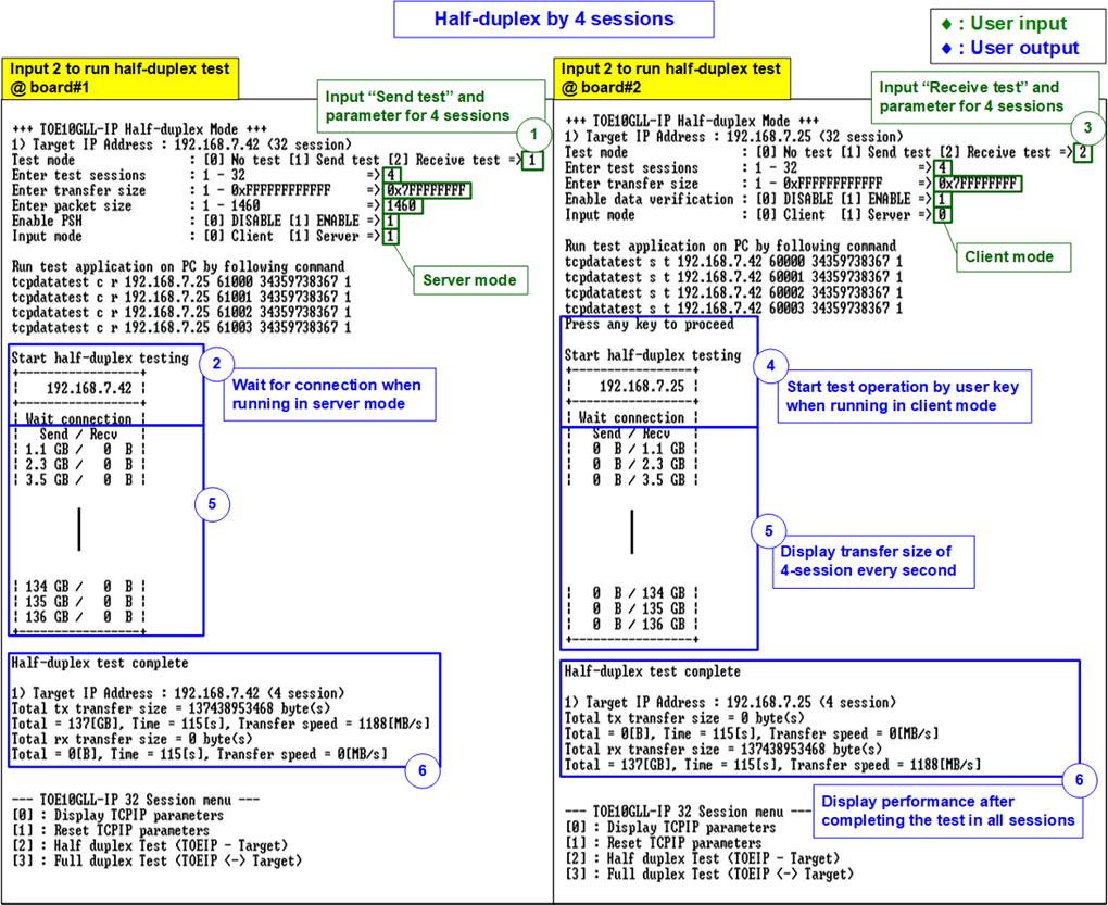
Figure 4‑4 Four-session half-duplex test (FPGA-to-FPGA) by using 1460-byte packet size
Figure 4‑5 shows the example of thirty-two-session half duplex test (FPGA-to-FPGA) when using 1460-byte packet size. Comparing to Figure 4‑4, the performance of running four-session and thirty-two-session -session is not different.

Figure 4‑5 Thirty-two-session half-duplex test (FPGA-to-FPGA) by using 1460-byte packet size
4.4 Full duplex Test
To transfer data in both directions between two FPGAs, select ‘3’ to run full-duplex test on the FPGA@board1 and FPGA@board2. The full-duplex test allows user to assign test parameters on console for each target separately. The sequence to run the test is shown as follows.
Note: The mode set in full-duplex test to open and close the connection is assigned. The client creates and terminates the connection while the server waits for open and terminate the connection. It does not relate to the initialization mode which is set to be Client, Server, or Fixed-MAC mode.
1) On FPGA@board1 console running as Server, input test parameters under full-duplex test menu.
a) Input test mode: ‘0’-Disable and skip to assign the next session, ‘1’-Full-duplex test.
b) Input test sessions: Number of sessions that will be tested. Valid range is 1 to number of sessions in this target.
c) Input transfer size: Unit of transfer size is byte. Valid value is 1 - 0xFFFF_FFFF_FFFF. The input is decimal unit when input only digit number. User adds “0x” to be a prefix for hexadecimal unit.
d) Input packet size: Unit of packet size is byte. Valid value is 1 – 1460. The input is decimal unit when input only digit number. User adds “0x” to be a prefix for hexadecimal unit.
e) Enable PSH: TCP flag to inform that the target device should return acknowledgement packet for the latest transmitted data immediately. Input ‘0’ to disable PSH flag or ‘1’ to enable PSH flag.
f) Input data verification mode: Input ‘1’ to enable data verification sent from FPGA@board2.
g) Input Mode: Open connection mode. Input ‘1’ to transfer as Server mode.
The input assignment is repeated until all targets are assigned.
2) If all inputs on FPGA@board1 console are valid, the parameter of the active target is displayed. “Wait connection” is displayed to wait until Client (FPGA@board2) sends request for the new connection.
3) On FPGA@board2 console running as Client, input test parameters under full-duplex test menu.
a) Input test mode: ‘0’-Disable and skip to assign the next session, ‘1’-Full-duplex test.
b) Input test sessions: Number of sessions that will be tested. Valid range is 1 to number of sessions in this target. This value must be equal to number of test sessions in step 1b).
c) Input transfer size: Unit of transfer size is byte. Valid value is 1 - 0xFFFF_FFFF_FFFF. The input is decimal unit when input only digit number. User adds “0x” to be a prefix for hexadecimal unit. This value must be equal to total transfer size in step 1c).
d) Input packet size: Unit of packet size is byte. Valid value is 1 – 1460. The input is decimal unit when input only digit number. User adds “0x” to be a prefix for hexadecimal unit.
e) Enable PSH: TCP flag to inform that the target device should return acknowledgement packet for the latest transmitted data immediately. Input ‘0’ to disable PSH flag or ‘1’ to enable PSH flag.
f) Input data verification mode: Input ‘1’ to enable data verification sent from FPGA@board1.
g) Input Mode: Open connection mode. Input ‘0’ to transfer as Client mode.
The input assignment is repeated until all targets are assigned.
4) If all inputs on FPGA@board2 console are valid, “Press any key to proceed” is shown. After pressing some key on FPGA@board2 console, the ports are created.
5) Current amount of transferred data is displayed on both consoles every second. Both consoles show the amount of transferred data in both directions for each target.
6) “Full-duplex test complete” is displayed on both consoles after all connection are closed. Finally, total amount of transferred data and performance of each target are displayed on both consoles.
Figure 4‑6 shows the example of thirty-two-session full duplex test (FPGA-to-FPGA) when using 1460-byte packet size. The left window is the Server console (FPGA@board#1) and the right window is Client console (FPGA@board#2).
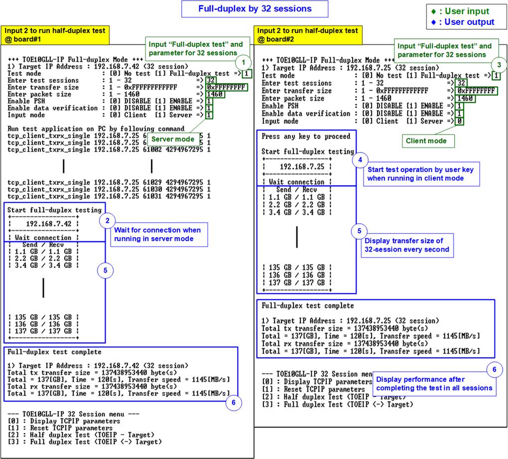
Figure 4‑6 Thirty-two-session full duplex test (FPGA-to-FPGA) with 1460-byte packet size
5 Revision History
|
Revision |
Date |
Description |
|
1.0 |
22-Apr-22 |
Initial version release |