1 Introduction
The default TOE10GLL-IP reference design implements one TOE10GLL-IP for transferring TCP payload data by using one session. For some applications such as FINTECH, it always uses more than one session for transfer many data types at the same time. To support multi-session feature with the lowest latency time, many TOE10GLL-IPs configured in Cut-through mode are applied but shares the same Ethernet MAC via adapter.

Figure 1‑1 Low-latency solution
This document describes the reference design that includes thirty-two TOE10GLL-IPs that share the same 10GEMAC and PHY to support thirty-two sessions. User logic and Test application for running multiple-session demo are almost similar to one-session demo, except the test application of full-duplex demo. “tcp_client_txrx_single” is applied to run on PC instead. This application is run the test for one round, not forever loop like “tcp_client_txrx”.
Though the multiple-session demo implements thirty-two sessions, the user can enable each TOE10GLL-IP independently to check the performance or the operation when using less than thirty-two sessions. Also, the transfer direction of each session can be configured independently. The user can modify the multiple-session reference design to adjust the number of sessions to match the system requirement. More details of the demo are described as follows.
2 Hardware overview
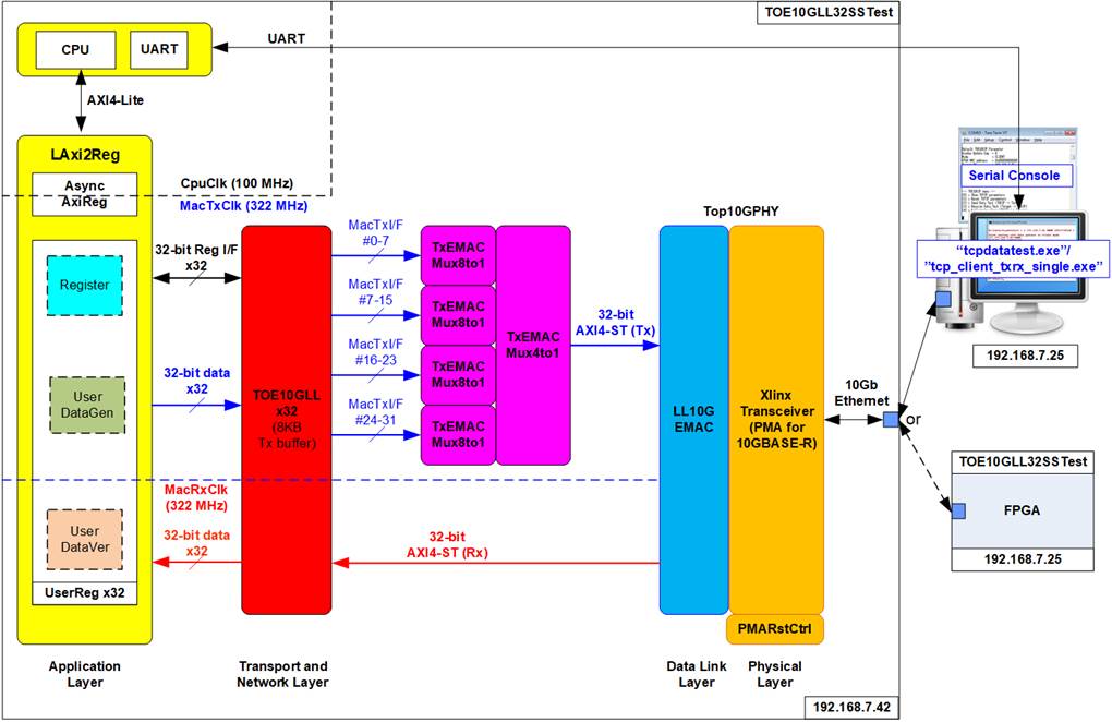
Figure 2‑1 Demo Block Diagram
The test system includes CPU for the ease of user interface and flexibility of test environment. User can input the test parameters such as network parameters and transfer size. Also, the current status of the test system such as current transfer size is displayed on Serial console for monitoring the test progress. To connect the hardware with CPU system, AXI4-Lite bus must be implemented. LAxi2Reg is the interface module to convert AXI4-Lite interface to be the user interface of TOE10GLL-IP module. LAxi2Reg includes AsyncAxiReg which is designed to be asynchronous module between CpuClk which is the independent clock for running the CPU system and MacTxClk which is the clock output, generated by Xilinx transceiver module.
The thirty-two TOE10GLL-IPs is applied for running up to 32 sessions with one or many connect target devices. TOE10GLL-IP is configured to Cut-through mode to achieve the lowest latency time and integrates 8 KB Tx buffer to reduce total amount of buffer size in the system. Therefore, test performance may be reduced from one session demo. Each TOE10GLL-IP connects to each UserReg within LAxi2Reg module to control and monitor the TOE10GLL-IP. UserReg consists of UserDataGen module which is the 32-bit test data generator and UserDataVer module which verifies the data, extracted from received packet. Register files inside UserReg are written and read by CPU firmware through AXI4-Lite bus. Another side of thirty-two TOE10GLL-IPs which have thirty-two MacTxI/F are connected to 10G Ethernet MAC controller (LL10GEMAC-IP) via four TxEMACMux8to1 modules and one TxEMACMux4to1 module. While Rx interface of 10G Ethernet MAC controller is fed to thirty-two TOE10GLL-IPs directly. LL10GEMAC-IP implements the Ethernet MAC layer and PCS layer with less latency time. Tx and Rx interface of AXI4-ST are run in the different clock domains: MacTxClk and MacRxClk respectively.
LL10GEMAC-IP provided by Design Gateway requires to run with Xilinx Transceiver which is configured to be PMA module for 10GBASE-R interface. PMARstCtrl is designed to control the reset sequence of Xilinx Transceiver
Another side of 10Gb Ethernet is the target device, Test PC or another FPGA board. When using TestPC, the test application (tcpdatatest and tcp_client_txrx_single) must be run for transferring TCP data with TOE10GLL-IP. Otherwise, another FPGA board is applied by implementing multiple TOE10GLL-IPs to transfer data in the different direction to show better performance.
2.1 Xilinx Transceiver (PMA for 10GBASE-R)
PMA IP core for 10Gb Ethernet (BASE-R) can be generated by using Vivado IP catalog. In FPGA Transceivers Wizard, the user uses the following settings.
· Transceiver configuration preset : GT-10GBASE-R
· Encoding/Decoding : Raw
· Transmitter Buffer : Bypass
· Receiver Buffer : Bypass
· User/Internal data width : 32
The example of Transceiver wizard in Ultrascale model is described in the following link.
https://www.xilinx.com/products/intellectual-property/ultrascale_transceivers_wizard.html
2.2 LL10GEMAC
The IP core by Design Gateway implements low-latency EMAC and PCS logic for 10Gb Ethernet (BASE-R) standard. The user interface is 32-bit AXI4-stream bus. Please see more details from LL10GEMAC datasheet on our website.
https://dgway.com/products/IP/Lowlatency-IP/dg_ll10gemacip_data_sheet_xilinx_en.pdf
2.3 PMARstCtrl
When the buffer inside Xilinx Transceiver is bypassed, the user logic must control reset signal of Tx and Rx buffer. The module is designed by state machine to run following step.
(1) Assert Tx reset of the transceiver to ‘1’ for one cycle.
(2) Wait until Tx reset done, output from the transceiver, is asserted to ‘1’.
(3) Finish Tx reset sequence and de-assert Tx reset to allow the user logic beginning Tx operation.
(4) Assert Rx reset to the transceiver.
(5) Wait until Rx reset done is asserted to ‘1’.
(6) Finish Rx reset sequence and de-assert Rx reset to allow the user logic beginning Rx operation.
2.4 TOE10GLL
TOE10GLL-IP is the IP core provided by Design Gateway to implement the TCP/IP stack and offload engine for the low latency solution. User interface has two signal groups, i.e., control signals and data signals. The IP can be configured to run in two modes: Cut-through mode and Simple mode. Also, Tx buffer can be configured to balance resource utilization and test performance. TOE10GLL-IP in this reference design is configured to Cut-through mode and 8 KB Tx buffer. More details are described in datasheet.
https://dgway.com/products/IP/Lowlatency-IP/dg_toe10gllip_data_sheet_xilinx_en.pdf
2.5 TxEMACMux8to1 and TxEMACMux4to1
The system consists of thirty-two TOE10GLL-IPs which share the same EMAC. To meet timing constraint in some FPGA models, two multiplexer modules are designed, i.e., TxEMACMux8to1 and TxEMACMux4to1. To transfer the transmitted packet from thirty-two TOE10GLL-IPs to one EMAC, four TxEMACMux8to1s are applied to connect with TOE10GLL-IP#0-7, #8-15, #16-23, and #24-31. Then, the transmitted packet output from four TxEMACMux8to1s are fed to one TxEMACMux4to1 for transferring with EMAC. By using two-step multiplexers, the latency time is increased by 2 clock cycles, comparing to using one TOE10GLL-IPs and one MEAC. If the system consists eight or less than eight TOE10GLL-IPs, it can use one-step multiplexer to reduce latency time. More details about TxEMACMux8to1 and TxEMACMux4to1 are described as follows.
2.5.1 TxEMACMux8to1
The core signal inside those modules is rChSel that is applied to select one active TOE10GLL-IPs module from eight modules. Timing diagram of this module is displayed in Figure 2‑2.
1) If current channel (Ch#7) does not transfer the data and the new channel requests to transfer data by asserting IP2MacTxValid to ‘1’, rChSel (the signal to indicate the active channel) will switch the value to the new channel. In Figure 2‑2, there are two channels send the request at the same time. The selected channel will be the nearest channel of the order 0 -> 1 -> 2 ->…->7 -> 0. Therefore, Ch#0 is higher priority than Ch#1 when the current channel is 7. IP2MacTxReady of the selected channel (Ch#0) is asserted to ‘1’ to accept the first data.
2) The input signals of the selected channel (Ch#0), i.e., IP2MacTxEOP (end-of-packet) and IP2MacTxData (32-bit data) are loaded to the output signals of EMAC (tx_last and tx_data respectively). Also, tx_valid is asserted to ‘1’ to start sending the new packet to EMAC.
3) When EMAC is not ready to receive data by de-asserting tx_ready to ‘0’, all output signals of EMAC hold the same value. Also, IP2MacTxReady of the active channel is de-asserted to ‘0’ to hold the input signals from the source.
4) After EMAC re-asserts tx_ready to accept the data, the next output signals to EMAC will be loaded from the internal latch register (rTxDataLat). The internal latch register is designed to load the data from the active source when IP2MacTxReady is asserted to ‘1’. Therefore, the latch register is the temp buffer for storing the unsent data to EMAC when EMAC pauses data transmission.
5) After accepting the final data of a packet from the active channel, the next active channel is scanned. If IP2MacTxValid of remaining channels is asserted, rChSel will update the value following the rule (0 -> 1 -> 2 ->…-> 7 ->0). In Figure 2‑2, the next active channel is Ch#1, so rChSel is set to 001b to accept the data from Ch#1.
6) The input signals (IP2MacTxEOP, and IP2MacTxData) of the active channel (Ch#1) are forwarded to be the output signals of EMAC (tx_last, and tx_data) until the final data of the packet is transferred.

Figure 2‑2 TxEMACMux8to1
2.5.2 TxEMACMux4to1
The logic inside TxEMACMux4to1 is almost similar to TxEMACMux8to1, but rChSel is updated to two-bit signal to select Ch#0 – Ch#3. The channel order in this module is 0 -> 1 -> 2 -> 3 -> 0.
2.6 CPU and Peripherals
32-bit AXI4-Lite is applied to be the bus interface for the CPU accessing the peripherals such as Timer and UART. To control and monitor the test system, the control and status signals are connected to register for CPU access as a peripheral through 32-bit AXI4-Lite bus. CPU assigns the different base address and the address range to each peripheral for accessing one peripheral at a time.
In the reference design, the CPU system is built with one additional peripheral to access the test logic. Therefore, the hardware logic must be designed to support AXI4-Lite bus standard for CPU write access and read access. LAxi2Reg module is designed to connect the CPU system as shown in Figure 2‑3.
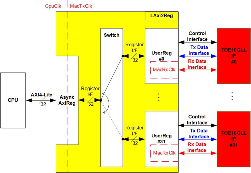
Figure 2‑3 LAxi2Reg block diagram
Similar to the default TOE10GLL-IP reference design, LAxi2Reg consists of AsyncAxiReg and UserReg. To support multiple sessions, thirty-two UserRegs are integrated. Therefore, switch logic is designed to decode the requested address by AsyncAxiReg. Five upper bits are applied for selecting the active channel from 32 channels (00000b-UserReg#0, 00001b-UserReg#1, …, 11111b-UserReg#31).
AsyncAxiReg and UserReg are the same module applied in the default TOE10GLL-IP reference design. AsyncAxiReg converts the AXI4-Lite signals to be the simple register and includes asynchronous logic to support clock domain crossing between CpuClk domain and MacTxClk domain. UserReg is the example of user logic to interface with TOE10GLL-IP. Tx data interface and Rx data interface of TOE10GLL-IP are run in different clock domain, MacTxClk and MacRxClk. Therefore, UserReg module consists of the logics which run in two clock domains. More details of AsyncAxiReg and UserReg are described as follows
2.6.1 AsyncAxiReg

Figure 2‑4 AsyncAxiReg Interface
The signal on AXI4-Lite bus interface can be split into five groups, i.e., LAxiAw* (Write address channel), LAxiw* (Write data channel), LAxiB* (Write response channel), LAxiAr* (Read address channel) and LAxir* (Read data channel). More details to build custom logic for AXI4-Lite bus are described in following document.
According to AXI4-Lite standard, the write channel and the read channel are operated independently. Also, the control and data interface of each channel are run separately. So, the logic inside AsyncAxiReg to interface with AXI4-Lite bus is split into four groups, i.e., Write control logic, Write data logic, Read control logic, and Read data logic as shown in the left side of Figure 2‑4. Write control I/F and Write data I/F of AXI4-Lite bus are latched and transferred to be Write register interface with clock domain crossing registers. Similarly, Read control I/F of AXI4-Lite bus are latched and transferred to be Read register interface. While the returned data from Register Read I/F is transferred to AXI4-Lite bus by using clock domain crossing registers. In register interface, RegAddr is shared signal for write and read access. Therefore, it loads the address from LAxiAw for write access or LAxiAr for read access.
The simple register interface is compatible with single-port RAM interface for write transaction. The read transaction of the register interface is slightly modified from RAM interface by adding RdReq and RdValid signals for controlling read latency time. The address of register interface is shared for write and read transaction, so user cannot write and read the register at the same time. The timing diagram of the register interface is shown in Figure 2‑5.
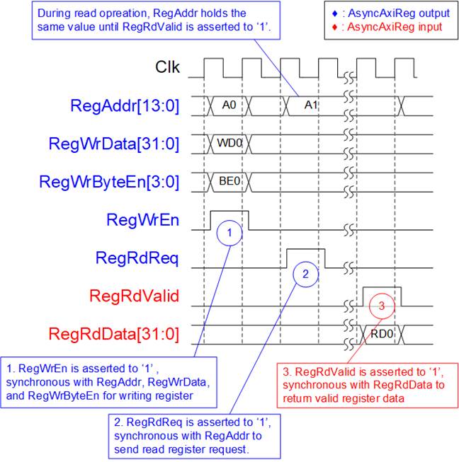
Figure 2‑5 Register interface timing diagram
1) To write register, the timing diagram is similar to single-port RAM interface. RegWrEn is asserted to ‘1’ with the valid signal of RegAddr (Register address in 32-bit unit), RegWrData (write data of the register), and RegWrByteEn (the write byte enable). Byte enable has four bits to enable 4-byte data. Bit[0], [1], [2], and [3] are equal to ‘1’ when RegWrData[7:0], [15:8], [23:16], and [31:24] are valid respectively.
2) To read register, AsyncAxiReg asserts RegRdReq to ’1’ with the valid value of RegAddr. 32-bit data is returned after receiving the read request. The slave detects RegRdReq asserted to start the read transaction. During read operation, the address value (RegAddr) does not change until RegRdValid is asserted to ‘1’. Therefore, the address can be used for selecting the returned data by using multiple levels of multiplexer.
3) The read data is returned on RegRdData bus by the slave with asserting RegRdValid to ‘1’. After that, AsyncAxiReg forwards the read value to LAxir* interface.
2.6.2 UserReg

Figure 2‑6 UserReg block diagram
UserReg module applied in 32-session demo is similar to 1-session demo, so please see more details about the hardware logic and the operation from 1-session demo document.
https://dgway.com/products/IP/Lowlatency-IP/dg_toe10gllip_refdesign_xilinx_en.pdf
As shown in Figure 2‑6, register map of one session uses 800h address area (0x0000 – 0x07FF), so 32-session is implemented by mapping to 10000h area as below.
· 0x0000 – 0x07FF: Session#0 hardware
· 0x0800 – 0x0FFF: Session#1 hardware
· …
· 0xF000 – 0xF7FF: Session#30 hardware
· 0xF800 – 0xFFFF: Session#31 hardware
The five upper bits are applied to select one of thirty-two TOE10GLL-IPs + UserRegs. More details of register map in 32-session demo is shown in Table 2‑1.
Table 2‑1 Register map Definition
|
Address |
Register Name |
Description |
|
Wr/Rd |
(Label in “toe10gll32test.c”) |
|
|
BA+0x0000 – BA+0x01FF: TOE10GLL-IP#0 interface BA+0x0200 – BA+0x03FF: LL10GEMAC-IP#0 interface More details of each signal are described in TOE10GLL-IP and LL10GEMAC-IP datasheet. |
||
|
BA+0x0000 – BA+0x00FF: Input signals of TOE10GLL-IP#0 (Write access only) |
||
|
BA+0x0000 |
TOE_RST_INTREG |
[0]: Mapped to RstB of TOE10GLL-IP |
|
BA+0x0004 |
TOE_OPM_INTREG |
[1:0]: Mapped to DstMacMode of TOE10GLL-IP [16]: Mapped to ARPICMPEn of TOE10GLL-IP |
|
BA+0x0008 |
TOE_SML_INTREG |
[31:0]: Mapped to SrcMacAddr[31:0] of TOE10GLL-IP |
|
BA+0x000C |
TOE_SMH_INTREG |
[15:0]: Mapped to SrcMacAddr[47:32] of TOE10GLL-IP |
|
BA+0x0010 |
TOE_DMIL_INTREG |
[31:0]: Mapped to DstMacAddr[31:0] of TOE10GLL-IP |
|
BA+0x0014 |
TOE_DMIH_INTREG |
[15:0]: Mapped to DstMacAddr[47:32] of TOE10GLL-IP |
|
BA+0x0018 |
TOE_SIP_INTREG |
[31:0]: Mapped to SrcIPAddr of TOE10GLL-IP |
|
BA+0x001C |
TOE_DIP_INTREG |
[31:0]: Mapped to DstIPAddr of TOE10GLL-IP |
|
BA+0x0020 |
TOE_TMO_INTREG |
[31:0]: Mapped to TimeOutSet of TOE10GLL-IP |
|
BA+0x0040 |
TOE_CMD_INTREG |
[1:0]: Mapped to TCPCmd of TOE10GLL-IP. When this register is written, TCPCmdValid of TOE10GLL-IP is asserted to ‘1’ for one cycle. |
|
BA+0x0044 |
TOE_SPN_INTREG |
[15:0]: Mapped to TCPSrcPort[15:0] of TOE10GLL-IP |
|
BA+0x0048 |
TOE_DPN_INTREG |
[15:0]: Mapped to TCPDstPort[15:0] of TOE10GLL-IP |
|
BA+0x0080 |
TOE_TIC_INTREG |
[0]: Set ‘1’ to clear read value of TOE_STS_INTREG[2] (TOE10GLL-IP interrupt) |
|
BA+0x0100 – BA+0x01FF: Output signals of TOE10GLL-IP#0 (Read access only) |
||
|
BA+0x0100 |
TOE_VER_INTREG |
[31:0]: Mapped to IP version of TOE10GLL-IP |
|
BA+0x0104 |
TOE_STS_INTREG |
[0]: Mapped to InitFinish of TOE10GLL-IP [1]: Mapped to TCPConnOn of TOE10GLL-IP [2]: TOE10GLL-IP Interrupt. Asserted to ‘1’ when IPInt of TOE10GLL-IP is asserted to ‘1’. This flag is cleared by TOE_TIC_INTREG. [20:16]: Mapped to IPState of TOE10GLL-IP |
|
BA+0x0108 |
TOE_INT_INTREG |
[31:0]: Mapped to IntStatus of TOE10GLL-IP |
|
BA+0x010C |
TOE_DMOL_INTREG |
[31:0]: Mapped to DstMacAddrOut[31:0] of TOE10GLL-IP |
|
BA+0x0110 |
TOE_DMOH_INTREG |
[15:0]: Mapped to DstMacAddrOut[47:32] of TOE10GLL-IP |
|
BA+0x0200 – BA+0x03FF: Output signals of LL10GEMAC-IP (Read access only) |
||
|
BA+0x0200 |
EMAC_VER_INTREG |
[31:0]: Mapped to IP version of DG LL10GEMAC-IP |
|
BA+0x0204 |
EMAC_STS_INTREG |
[0]: Mapped to Linkup of LL10GEMAC-IP |
|
BA+ BA+0x0400 – BA+0x07FF: UserDataGen#0 and UserDataVer#0 interface |
||
|
BA+0x0400 – BA+0x04FF: Input signals of UserDataGen#0 (Write access only) |
||
|
BA+0x0400 |
USRTX_CMD_INTREG |
[0]: Start flag to generate test data by UserDataGen. Set ‘1’ to start sending data. This flag is auto-cleared after running the operation. [1]: Set ‘1’ to clear USRTX_LENL/H_INTREG and USRTX_TMR_INTREG. |
|
BA+0x0420 |
USRTX_PKL_INTREG |
[10:0]: Packet length in byte unit for assigning TCPTxPkLen, input of TOE10GLL-IP. |
|
BA+0x0424 |
USRTX_PSH_INTREG |
[0]: PSH flag for assigning TCPTxPSH, input of TOE10GLL-IP |
|
BA+0x0428 |
USRTX_TDL_INTREG |
[31:0]: Bit[31:0] of total size in byte unit to generate test data by UserDataGen. The value is cleared by USRTX_CMD_INTREG[1]. |
|
BA+0x042C |
USRTX_TDH_INTREG |
[15:0]: Bit[47:32] of total size in byte unit to generate test data by UserDataGen. The value is cleared by USRTX_CMD_INTREG[1]. |
Address |
Register Name |
Description |
|
Wr/Rd |
(Label in “toe10gll32test.c”) |
|
|
BA+0x0500 – BA+0x05FF: Output signals of UserDataGen#0 (Read access only) |
||
|
BA+0x0500 |
USRTX_STS_INTREG |
[0]: Busy signal of UserDataGen (‘0’-Idle, ‘1’-Data is transmitting) |
|
BA+0x0504 |
USRTX_TMR_INTREG |
Timer value which shows latency time in Tx interface of TOE10GLL-IP [15:0]: Tx latency time of TOE10GLL-IP in clock cycle unit The value is cleared by USRTX_CMD_INTREG [1]. |
|
BA+0x0508 |
USRTX_LENL_INTREG G |
[31:0]: Bit[31:0] of complete size of transmitted data in byte unit which is calculated by the sum of TCPTxCplLen, output from TOE10GLL-IP. The value is cleared by USRTX_CMD_INTREG [1]. |
|
BA+0x050C |
USRTX_LENH_INTREG |
[15:0]: Bit[47:32] of complete size of transmitted data in byte unit which is calculated by the sum of TCPTxCplLen, output from TOE10GLL-IP. The value is cleared by USRTX_CMD_INTREG [1]. |
|
BA+0x0600 – BA+0x06FF: Input signals of UserDataVer#0 (Write access only) |
||
|
BA+0x0600 |
USRRX_CMD_INTREG |
[0]: Enable data verification of UserDataVer (‘0’: Disable data verification, ‘1’: Enable data verification) [1]: Set ‘1’ to clear USRRX_LENL/H_INTREG and USRRX_TMR_INTREG are reset. |
|
BA+0x0604 |
USRRX_RXC_INTREG |
[0]: Set ‘1’ to clear read value of USRRX_STS_INTREG[1] (TCPRxError of TOE10GLL-IP) |
|
BA+0x0700 – BA+0x07FF: Output signals of UserDataVer#0 (Read access only) |
||
|
BA+0x0700 |
USRRX_STS_INTREG |
[0]: Verify fail (‘0’-No error, ‘1’-Received data is incorrect) [1]: Receive error interrupt. Asserted to ‘1’ when TCPRxError from TOE10GLL-IP shows error status. This flag can be cleared by. USRRX_RXC_INTREG. |
|
BA+0x0704 |
USRRX_TMR_INTREG |
Timer value which shows latency time in Rx interface of TOE10GLL-IP [15:0]: Rx Latency time of TOE10GLL-IP in clock cycle unit. The value is cleared by USRRX_CMD_INTREG[1]. |
|
BA+0x0708 |
USRRX_ERR_INTREG |
[7:0]: Latch signal of TCPRxError, output of TOE10GLL-IP. The value does not change after detecting error. The value is reset after this register is read by CPU. |
|
BA+0x0720 |
USRRX_LENL_INTREG |
[31:0]: Bit[31:0] of current size of received data in byte unit which is counted when the packet received from TOE10GLL-IP is valid. The value is cleared by USRRX_CMD_INTREG[1]. |
|
BA+0x0724 |
USRRX_LENH_INTREG |
[15:0]: Bit[47:32] of current size of received data in byte unit which is counted when the packet received from TOE10GLL-IP is valid. The value is cleared by USRRX_CMD_INTREG [1]. |
|
BA+0x0728 |
USRRX_FAILPOSL_INTREG |
[31:0]: Bit[31:0] of the first position in byte unit that data verification detects failure. The value is cleared by USRRX_CMD_INTREG [1]. |
|
BA+0x072C |
USRRX_FAILPOSH_INTREG |
[15:0]: Bit[47:32] of the first position in byte unit that data verification detects failure. The value is cleared by USRRX_CMD_INTREG [1]. |
|
BA+0x0730 |
USRRX_EXPPAT_INTREG |
[31:0]: Expected data that IP should receive when data verification is failed. |
|
BA+0x0734 |
USRRX_RDPAT_INTREG |
[31:0]: Received data that is incorrect when data verification is failed. |
|
BA+0x0800 – BA+0xFFFF: Register Area of Session#1 – Session#31 |
||
|
BA+0x0800- BA-0x0FFF |
Similar to BA+0x0000 – BA+0x07FF, but this area is mapped to TOE10GLL-IP, UserDataGen, and UserDataVer for operating Session#1. LL10EMAC-IP area is mapped the same data as Session#0. |
|
|
BA+0x1000- BA-0x17FF |
Similar to BA+0x0000 – BA+0x07FF, but this area is mapped to TOE10GLL-IP, UserDataGen, and UserDataVer for operating Session#2. LL10EMAC-IP area is mapped the same data as Session#0. |
|
|
BA+0x1800- BA-0x1FFF |
Similar to BA+0x0000 – BA+0x07FF, but this area is mapped to TOE10GLL-IP, UserDataGen, and UserDataVer for operating Session#3. LL10EMAC-IP area is mapped the same data as Session#0. |
|
|
BA+0x2000- BA-0x3FFF |
This area is mapped to Session#4 – Session#7.
|
|
|
BA+0x4000- BA-0x7FFF |
This area is mapped to Session#8 – Session#15. |
|
|
BA+0x8000- BA-0xFFFF |
This area is mapped to Session#16 – Session#31. |
|
3 CPU Firmware (FPGA)
For running the multisession reference design and further test modification, user should realize the information below.
1) Two end points of the communication are referred, i.e., FPGA#0 (left) and the target (right). The FPGA#0 always contains thirty-two TOE10GLL-IPs while the target can be PC with test application or FPGA#1 with TOE10GLL-IP(s) as shown in Figure 2‑1.
2) In FPGA#0, up to thirty-two TCP ports/sessions are supported by using thirty-two TOE10GLL-IPs with the same FPGA#0 IP address. It does not need to run all thirty-two TOE10GLL-IPs. For example, sixteen TOE10GLL-IPs is not used when running sixteen sessions in FPGA#0.
3) In the target, test system can be applied by using multiple targets to communicate with FPGA#0 when Ethernet switch is added to the system. Each target has unique IP address. However, the total amount of session from all target is up to thirty-two sessions

Figure 3‑1 Example when running with two targets in test system
Figure 3‑1 shows the example to run multisession design by using two target devices for operating thirty-two sessions and three sessions respectively. In the left side, the first target by PC runs one application for operating one session while the second target by FPGA#1 enables thirty-one TOE10GLL-IPs for operating thirty-one sessions. In the right side, the first target by PC runs two applications for operating two sessions while the second target by FPGA#1 runs one TOE10GLL-IPs for operating one session.
The hardware of multisession demo can assign its own target parameters individually, so it supports to run 32 sessions with 32 target devices. However, the CPU firmware is simplified by supporting up to two target devices. Many parameters are shared and have some relations to reduce the variable usage in the firmware. The example of test parameter setting in the firmware when two targets with 2-session and 3-session are shown in Table 3‑1.
Table 3‑1 Example test parameters
|
Target index |
Target#0 |
Target#1 |
|||
|
Session index |
Session#0 |
Session#1 |
Session#0 |
Session#1 |
Session#2 |
|
TOE10GLL index |
TOE10GLL#0 |
TOE10GLL#1 |
TOE10GLL#2 |
TOE10GLL#3 |
TOE10GLL#4 |
|
FPGA MAC address |
FPGA MAC address |
||||
|
FPGA IP address |
FPGA IP address |
||||
|
Init mode |
Init mode |
FIXED |
Init mode |
FIXED |
FIXED |
|
ARP/ICMP Enable |
Enable |
Disable |
Enable |
Disable |
Disable |
|
Target MAC address |
Target MAC address#0 |
Target MAC address#1 |
|||
|
Target IP address |
Target IP address#0 |
Target IP address#1 |
|||
|
FPGA port number |
FPGAPort#0 |
(FPGAPort#0)+1 |
FPGAPort#1 |
(FPGAPort#1)+1 |
(FPGAPort#1)+2 |
|
Target port number |
TarPort#0 |
(TarPort#0)+1 |
TarPort#1 |
(TarPort#1)+1 |
(TarPort#1)+2 |
The rule of parameter assignment in the firmware is listed as follows.
· Maximum number of targets is 2.
· The index of TOE10GLL is calculated by the target index and the session index.
Target#0: TOE10GLL index = Session index
Target#1: TOE10GLL index = (Total number of sessions in Target#0) + Session index
· FPGA MAC address: Same value for all sessions
· FPGA IP address: Same value for all sessions
· Init mode: Same value for the first session in each target. Other sessions are set to Fixed-MAC mode.
· ARP/ICMP Enable: Only the first session in each target can be set while other sessions are set to Disable.
· Target MAC address: Share the same value for all sessions in each target.
· Target IP address: Share the same value for all sessions in each target.
· FPGA port number: Set the value to the first session in each target. Other sessions are calculated by counting up to the next value.
· Target port number: Set the value to the first session in each target. Other sessions are calculated by counting up to the next value.
User can modify the firmware to assign the parameters of each session individually for more flexibility. There is no limitation in the hardware to support unique parameters for each TOE10GLL-IP.
Figure 3‑2 shows the boot console when running the demo. There are four steps to initialize the hardware, described as follows.
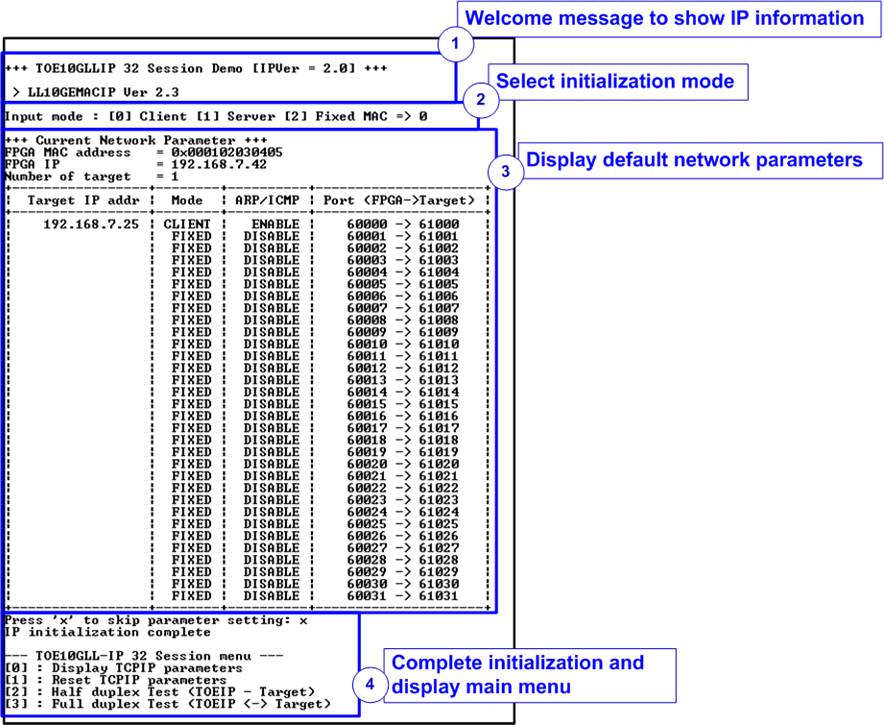
Figure 3‑2 Message on the console during initialization process
1) After FPGA boot-up, 10G Ethernet link up status (EMAC_STS_INTREG[0]) is polling. The CPU waits until ethernet link is established and then displays welcome message to show IP information.
2) The menu to select the initialization mode of TOE10GLL-IP is displayed which can be set to Client, Server, or Fixed-MAC mode. After that, the initialization mode is assigned to the first session of each target. The other sessions are set to Fixed-MAC mode.
Note:
- In Client mode initialization, TOE10GLL-IP sends ARP request to get the MAC address of the target device from ARP reply. In Server mode initialization, TOE10GLL-IP waits until ARP request is received to decode MAC address and return ARP reply. In Fixed-MAC mode initialization, the user needs to know MAC address of the target device because TOE10GLL-IP does not transfer ARP packet.
- When running the test environment by using FPGA board and Test PC, it is recommended to set FPGA run as client mode.
- When the test environment uses FPGA and FPGA, there are three solutions to initial the connection between two boards, i.e., Client <-> Server, Client <-> Fixed MAC, and Fixed MAC <-> Fixed MAC.
3) CPU displays default value of the network parameters in the selected initialization mode, i.e., FPGA MAC address, FPGA IP address, FPGA port number, Target IP address, and Target port number. The firmware has two default parameter sets for the operation mode. First is the parameter set for Server mode and another is the parameter set for Client/Fixed MAC mode. For Fixed MAC mode, there is an extra parameter -Target MAC address. The user can select to complete the initialization process by using default parameters or updating some parameters. The details to change the parameter are described in Reset IP menu (topic 3.2).
4) CPU waits until the IP completes the initialization process by checking if InitFinish (TOE_STS_INTREG[0]) is equal to ’1’. After that, “IP initialization complete” is displayed with the main menu. There are four test operations in the main menu. More details of each menu are described as follows.
3.1 Display parameters
This menu is designed to display the current value of all active TOE10GLL-IP parameters. Source parameters which are shared for all sessions display at the top lines. While the parameters of each session are listed in the table. The sequence of display parameters is as follows.
1) Read and display common parameters that are shared for all sessions, i.e., FPGA MAC address and FPGA IP address.
2) Read and display the number of target devices.
3) Read and display the parameters and unique parameters of each session. Target MAC address (when using Fixed-MAC mode) and Target IP address are displayed once for each target. While the initialization mode, ARP/ICMP enable, FPGA port number and Target port number are displayed individually for each session. The parameters are read until current target number and current session number are last value.
3.2 Reset parameters
This menu is designed to change network parameters of TOE10GLL-IP such as IP address and source port number and assert IP reset after the parameters are updated. The IP starts initialization by using the updated parameters and CPU waits until the initialization is completed. The step to reset parameters is as follows.
1) Display all parameters on the console.
2) Ask user to skip (use current parameters) or set new parameter values.
a. Press ‘x’ on keyboard to skip. The current parameters are used and continue to step 6.
b. Press other keys to start setting parameters (continue to step 3).
3) Receive initialization mode from user and confirm that input is valid.
a. If input mode is invalid, mode value will not change and continue to step 4.
b. If input mode is valid and the value is changed from previous value, the current parameter set of new mode is displayed on the console. Next, user inputs ‘x’ to use the current parameters (continue to step 6) or inputs other keys to set the new parameters (continue to step 4).
4) Receive the common parameters from user, i.e., FPGA MAC address and FPGA IP address. If an input value is invalid, the parameter is not changed. Also, receive the amount of the target. If the amount of target is updated, user needs to set all parameters by valid value.
5) Receive parameters of each target from user, i.e., ARP/ICMP Enable, Target MAC address (only in Fixed-MAC mode), Target IP address, port number of the first session, and the number of sessions. If an input value is invalid, the input is not changed.
Note:
- The port number is assigned to the first session while the other sessions are calculated by using count up value.
- The initialization mode of the first session is assigned by user input while the other sessions are set to Fixed-MAC mode. The target MAC address of the other sessions are set by the target MAC address of the first session.
6) Force reset to IP by setting TOE_RST_INTREG[0]=’1’.
7) Set current parameters to all TOE10GLL-IP registers that are active such as TOE_SML_INTREG and TOE_DIP_INTREG.
8) Start IP initialization for the first session of each target by running following steps.
i) De-assert TOE10GLL-IP reset by setting TOE_RST_INTREG[0]=’0’ to start IP initialization process for all targets.
ii) Wait until the TOE10GLL-IP finishes initialization process (TOE_STS_INTREG[0]=’1’).
9) Start IP initialization for the other sessions of each target by running following steps.
i) Read the Target MAC address (TOE_DMOL/H_INTREG) of the first session to set the same value to the other sessions in each target.
ii) Set Target MAC address (TOE_DMIL/H_INTREG) by the same value as the first session.
iii) Set initialization mode (TOE_OPM_INTREG) to be Fixed-MAC mode.
iv) De-assert TOE10GLL-IP reset by setting TOE_RST_INTREG[0]=’0’ to start IP initialization process.
v) Wait until the TOE10GLL-IP finishes initialization process (TOE_STS_INTREG[0]=’1’).
3.3 Half Duplex Test
This menu is applied to transfer data in single direction – send data or receive data. Test parameters of each target are assigned by user, i.e., test mode (Send, Receive, or no operation), the number of test sessions, transfer size, packet size (Send mode), PSH flag (Send mode), verification enable flag (Receive mode), and connection mode (Client mode which is active open or Server mode which is passive open). The operation is cancelled if some inputs are invalid.
Note: Server or Client which is assigned to connection mode is applied to select the type of open port command. It is not related to initialization mode which can be assigned to Client, Server, or Fixed-MAC mode.
32-bit incremental data is generated to send or verify data. The operation is finished when all data of all test session are transferred completely. When running the test with PC, test application (tcpdatatest) must be run.
The sequence of the test is as follows.
1) Display target IP address and the number of the sessions of the current target, starting from target#0.
2) Receive parameters for each target, i.e., test mode, the number of test sessions, transfer size, data verification mode or packet size with PSH flag mode, and connection mode from user. After that, verify if all inputs are valid.
3) Repeat step 2) to get the parameters of the next target if the current target is not the last target.
4) Set UserReg registers following the transfer direction.
a. For send data, set flag to clear status of UserDataGen (USRTX_CMD_INTREG[1]=’1’), transmitted size (USRTX_TDL/TDH_INTREG), packet size (USRTX_PKL_INTREG), PSH flag mode (USRTX_PSH_INTREG), and start sending flag (USRTX_CMD_INTREG[0]=’1’).
b. For receive data, set command register of UserDataVer to clear status and verification enable flag (USRRX_CMD_INTREG[2:1]=11b and USRRX_CMD_INTREG[0]=VerEn flag).
5) Prepare the device to opened the connection.
a. If the connection mode = Server (Passive mode), CPU sets TOE_CMD_INTREG=2 (Passive open) to TOE10GLL-IP. After that, CPU displays the recommended parameters to run test application on PC by Client mode.
b. If the connection mode = Client (Active mode), CPU displays the recommended parameters to run test application on PC by Server mode. After that, “Press any key to proceed” is displayed to wait until user runs the target to listen the connection (passive open). User needs to enter some keys on the console to start connection establishment.
6) Set the current state variable to be WAIT_CON.
7) If the connection mode = Client, start open connection by setting TOE_CMD_INTREG =1 (Active open).
8) Wait until TCPConnOn status (TOE_STS_INTREG [1]) is asserted to ‘1’. After that, the current state variable changes to CONNECTED. Now connection establishment is completed and the next step is transferring data.
9) The steps for transferring data depends on transfer direction.
Send data mode
i) Confirm the state variable is equal to CONNECTED and TOE10GLL-IP is not busy (TOE_STS_INTREG[3]=’0’). If not, skip to operate the next session.
ii) Continue the next step only when the connection is still ON (TOE_STS_INTREG[1] =’1’). Otherwise, the state variable is set to ERROR.
iii) Check total transfer size variable. If total transfer size is equal to the set value, run active close command by setting TOE_CMD_INTREG=3. Also, busy status of user logic (USRTX_STS_INTREG[0]) must be equal to 0. After that, the state variable is set to CLOSED. If busy status is still asserted to ‘1’, the state variable is set to ERROR.
Receive data mode
i) Confirm the state variable is equal to CONNECTED.
ii) Read the connection status. If connection status is OFF (TOE_STS_INTREG[1]=’0’), set the state variable to CLOSED
Every second the test progress and connection status of all sessions is displayed. If the data is still transferred, total amount of transmitted data (USER_TXLENL/H_INTREG) and received data (USER_RXLENL/H_INTREG) in each target are calculated and displayed on the console
10) For the session that has just run receive test, compare receive length of user logic (USER_RXLEN/H_REG) with the set value from user and read verification result (USRRX_STS_INTREG [0]). Error message is displayed if receive length or data verification is error.
11) Calculate performance and latency time, and then display a test result on the console.
3.4 Full duplex test
This menu is designed to run full duplex test by transferring data between FPGA and another device (PC/FPGA) in both directions by using the same port number at the same time. Five inputs are received from user, i.e., test mode (full-duplex or no operation), the number of test sessions, transfer size of both directions, packet size for send test, PSH flag for send test, verification enable flag for receive test, and connection mode (Client mode which is active open or Server mode which is passive open). The operation is cancelled if some inputs are invalid.
Note: Server or Client which is assigned to connection mode is applied to select the type of open port command. It is not related to initialization mode which can be assigned to Client, Server, or Fixed-MAC mode.
When running the test by using PC, the transfer size set on FPGA must be matched to the size set on test application (tcp_client_txrx_single). Also, Connection mode on FPGA when running with PC must be Server (Passive open)
The sequence of this test is as follows.
1) Display target IP address and the number of the sessions of the current target, starting from target#0.
2) Receive parameters for each target, i.e., test mode, the number of test sessions, transfer size, packet size with PSH flag mode, data verification mode, and connection mode from user. After that, verify if all inputs are valid.
3) Repeat step 2) to get the parameters of the next target if the current target is not the last target.
4) Set UserReg registers for starting the test operation for both transfer directions.
i) To receive data, set command register of UserDataVer to clear status and verification enable flag (USRRX_CMD_INTREG[2:1]=11b and USRRX_CMD_INTREG[0] =VerEn flag).
ii) To send data, set flag to clear status of UserDataGen (USRTX_CMD_INTREG[1]=’1’), transmitted size (USRTX_TDL/TDH_INTREG), packet size (USRTX_PKL_INTREG), PSH flag mode (USRTX_PSH_INTREG), and start sending flag (USRTX_CMD_INTREG[0]=’1’).
5) Prepare the device to opened the connection.
a. If the connection mode = Server (Passive mode), CPU sets TOE_CMD_INTREG=2 (Passive open) to TOE10GLL-IP. After that, CPU displays the recommended parameters to run test application on PC by Client mode.
b. If the connection mode = Client (Active mode), CPU displays “Press any key to proceed” to wait until user runs the target to listen the connection (passive open). User needs to enter some keys on the console to start connection establishment.
6) Set the current state variable to be WAIT_CON.
7) If the connection mode = Client, start open connection by setting TOE_CMD_INTREG =1 (Active open).
8) Wait until TCPConnOn status (TOE_STS_INTREG [1]) is asserted to ‘1’. After that, the current state variable changes to CONNECTED. Now connection establishment is completed and the next step is transferring data.
9) Start data transferring by running following steps.
i) Confirm the state variable is equal to CONNECTED and TOE10GLL-IP is not busy (TOE_STS_INTREG [3]=’0’). If not, skip to operate the next session.
ii) Check the connection status by reading TOE_STS_INTREG[1].
a. If the connection is ON, continue the next step.
b. If the connection is OFF, confirm the connection mode is passive and remaining transmit length variable is equal to 0. After that, sets the state variable to CLOSED. If the session is active or the remaining transmit length is not equal to 0, the state variable changes to ERROR.
iii) Check total amount of received data and transmitted data.
a. If total amount of both transmitted and received data are not equal to the set value, return to step 9i).
b. If total amount of both transmitted and received data are equal to the set value, check the connection mode. If it is active mode, send active close command by setting TOE_CMD_INTREG=3. After that, confirm busy status of user logic must be de-asserted (USRTX_STS_INTREG [0]=’0’) and change the state variable to CLOSED. If busy is not de-asserted, the state variable is set to ERROR.
Every second the test progress and connection status of all sessions is displayed. If the data is still transferred, total amount of transmitted data (USER_TXLENL/H_INTREG) and received data (USER_RXLENL/H_INTREG) in each target are calculated and displayed on the console.
10) Check the result and the error, similar to step 10) of Half duplex test.
11) Calculate performance and latency time, and then display a test result on the console.
3.5 Function list in User application
This topic describes the function list to run TOE10GLL-IP operation.
|
unsigned int cal_strlen(unsigned int num) |
|
|
Parameters |
num: integer input to calculate the string length |
|
Return value |
ret: the length of string for displaying |
|
Description |
Receive the input and then calculate the length of string to display this value in integer style. |
|
void init_param(void) |
|
|
Parameters |
None |
|
Return value |
None |
|
Description |
This function is called to set the parameters and reset the IP, following described in topic 3.2. |
|
void input_param(void) |
|
|
Parameters |
None |
|
Return value |
None |
|
Description |
Receive test parameters from user for test parameters, i.e., Initialization mode, FPGA MAC address, FPGA IP address, the number of targets, ARP/ICMP Enable, Target MAC address (when run in Fixed-MAC mode), Target IP address, FPGA port number, and Target port number. After receiving and verifying all parameters, the current value of all parameter is displayed by calling show_param function. |
|
unsigned int read_conon(unsigned int toe_index) |
|
|
Parameters |
toe_index: an index of TOE10GLL-IP |
|
Return value |
0: Connection is OFF, 1: Connection is ON |
|
Description |
Read value from TOE_STS_INTREG register of the selected TOE10GLL-IP and return only bit1 value to show connection status. |
|
void show_cursize(unsigned int *test_mode, unsigned int* test_session, unsigned int *cur_state) |
|
|
Parameters |
test_mode: pointer of array that stores test mode in each target which can be No test (0), Send test (1), Receive test (2), or Full-duplex (3) test_session: pointer of array that indicates number of test session in each target cur_state: pointer of array that stores current state variable in each target |
|
Return value |
None |
|
Description |
Read and display connection status of all session. After that, calculate the sum of the amount of transmitted data and received data from all sessions. After that, display total amount of transmitted data and received data on the console in Byte, KByte, MByte, GByte, TByte, or PByte unit. |
|
void show_interrupt (unsigned int toe_index, unsigned int target, unsigned int session) |
|
|
Parameters |
toe_index: an index of TOE10GLL-IP target: an index of target device session: an index of session in this target |
|
Return value |
None |
|
Description |
Read value from TOE_INT_INTREG of the selected TOE10GLL-IP. After that decode the interrupt type and display the result. Finally, clear interrupt by set ‘1’ to TOE_TIC_INTREG |
|
void show_ipaddr(unsigned int ip_addr) |
|
|
Parameters |
ip_addr: IP Address in hexadecimal unit |
|
Return value |
None |
|
Description |
Display IP Address in decimal unit |
|
void show_ipstate(unsigned int toe_index, unsigned int target, unsigned int session) |
|
|
Parameters |
toe_index: an index of TOE10GLL-IP target: an index of target device session: an index of session in this target |
|
Return value |
None |
|
Description |
Read current state value from TOE_STS_INTREG[20:16] of the selected TOE10GLL-IP. After that, decode and display the result |
|
void show_perf_header(unsigned int *test_mode) |
|
|
Parameters |
test_mode: pointer of array that stores test mode which can be No test (0), Send test (1), Receive test (2), or Full-duplex (3) |
|
Return value |
None |
|
Description |
When test mode is not “No test” (0), read Target IP address to display as the header of the current transfer size table. |
|
void show_perf_line(unsigned int *test_mode) |
|
|
Parameters |
test_mode: pointer of array that stores test mode which can be No test (0), Send test (1), Receive test (2), or Full-duplex (3) |
|
Return value |
None |
|
Description |
When test mode is not “No test” (0), display straight line to be a part of the table. |
|
void show_param(void) |
|
|
Parameters |
None |
|
Return value |
None |
|
Description |
Read the network parameters which is global variable and display as a table. The parameters are FPGA MAC address, FPGA IP address, the number of targets, Target MAC address, Target IP address, initialization mode, ARP/CMP enable flag, and port numbers. |
|
void show_result(unsigned int *test_mode, unsigned int *test_session, unsigned long long *total_len, unsinged int * ver_en, unsigned int *cur_state) |
|
|
Parameters |
test_mode: pointer of array that stores test mode which can be No test (0), Send test (1), Receive test (2), or Full-duplex (3) test_session: pointer of array to read the number of sessions total_len: pointer of array to store total amount of transferred data ver_en: pointer of array to indicate verification enable flag cur_state: pointer of array that stores current state variable |
|
Return value |
None |
|
Description |
Calculate total amount of transmitted data and received data of all active sessions. If some error is found, display error message. After that, display total amount of transmitted data and received data. Next, read timer value which are global parameters, convert to usec, msec, or sec unit, and then display on the console. Finally, transfer performance is calculated and displayed in MB/s unit. |
|
int toe_full_test(void) |
|
|
Parameters |
None |
|
Return value |
0: The operation is successful -1: Receive invalid input or error is found |
|
Description |
Run Full duplex test following description in topic 3.4. |
|
int toe_half_test(void) |
|
|
Parameters |
None |
|
Return value |
0: The operation is successful -1: Receive invalid input or error is found |
|
Description |
Run Half duplex test following description in topic 3.3. |
|
void update_cursize(unsigned int toe_index, unsigned long long *trn_size, unsigned int option) |
|
|
Parameters |
toe_index: an index of TOE10GLL-IP trn_size: pointer of array that store current transfer size option: 0-update Tx transfer size, 1-update Rx transfer size |
|
Return value |
None |
|
Description |
Read USRTX_LENL/H_REG or USRRX_LENL/H_REG of the selected TOE10GLL-IP. After that, return the result to trn_size variable. |
|
void wait_ethlink(void) |
|
|
Parameters |
None |
|
Return value |
None |
|
Description |
Read EMAC_STS_REG[0] and wait until ethernet connection is established. |
4 Test Software on PC
4.1 “tcpdatatest” for half duplex test

Figure 4‑1 “tcpdatatest” application usage
“tcpdatatest” is designed to run on PC for sending or receiving TCP data via Ethernet as Server or Client mode. In this demo, it is recommended to use Client mode. User sets parameters to select transfer direction and the mode. Six parameters are required as follows.
1) Mode: c –PC runs in Client mode and FPGA runs in Server mode
2) Dir : t – transmit mode (PC sends data to FPGA)
r – receive mode (PC receives data from FPGA)
3) ServerIP : IP address of FPGA when PC runs in Client mode (default is 192.168.7.42)
4) ServerPort: Port number of FPGA when PC runs in Client mode (default is 4000)
5) ByteLen : Total transfer size in byte unit. This input is used in transmit mode only and ignored in receive mode. In receive mode, the application is closed when the connection is terminated. In transmit mode, ByteLen must be equal to the total transfer size on FPGA that is set in receive data test menu.
6) Pattern:
0 – Generate dummy data in transmit mode or disable data verification in receive mode.
1 – Generate incremental data in transmit mode or enable data verification in receive mode.
Note: Window Scale: Optional parameter which is not used in the demo.
Transmit data mode
Following sequence is the sequence when test application runs in transmit mode.
1) Get parameters from the user and verify that all inputs are valid.
2) Create the socket and set socket options.
3) Create the new connection by using server IP address and server port number.
4) Allocate 1 MB memory to be send buffer.
5) Skip this step if the dummy pattern is selected. Otherwise, generate the incremental test pattern to send buffer.
6) Send data out and read total sent data from the function.
7) Calculate remaining transfer size.
8) Print total transmit size every second.
9) Repeat step 5) – 8) until the remaining transfer size is 0.
10) Calculate total performance and print the result on the console.
11) Close the socket and free the memory.
Receive data mode
Following sequence is the sequence when test application runs in receive mode.
1) Follow the step 1) – 3) of Transmit data mode.
2) Allocate memory to be receive buffer.
3) Read data from the receive buffer and calculate total amount of received data.
4) This step is skipped if data verification is disabled. Otherwise, received data is verified by the incremental pattern. Error message is printed out when data is not correct.
5) Print total amount of received data every second.
6) Repeat step 3) – 5) until the connection is closed.
7) Calculate total performance and print the result on the console.
8) Close socket and free the memory.
4.2 “tcp_client_txrx_single” for full duplex test
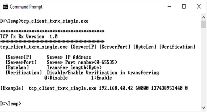
Figure 4‑2 “tcp_client_txrx_40G” application usage
This application is similar to “tcp_client_txrx_40G” application but it runs for one round, not forever loop. “tcp_client_txrx_single” application is designed to run on PC for sending and receiving TCP data through Ethernet by using the same port number at the same time. The application is run in Client mode, so user needs to input server parameters (the network parameters of TOE10GLL-IP). As shown in Figure 4‑2, there are four parameters to run the application, described as follows.
1) ServerIP : IP address of FPGA
2) ServerPort : Port number of FPGA
3) ByteLen : Total transfer size in byte unit. This value is total amount of transmitted data and the expected received data. Error message is displayed if total amount of received data is not equal to this value.
4) Verification :
0 – Generate dummy data for sending function and disable data verification for receiving function. When running this mode, it shows the best performance of full-duplex transfer.
1 – Generate incremental data for sending function and enable data verification for receiving function.
The sequence of test application is as follows.
(1) Get parameters from the user and verify that the input is valid.
(2) Create the socket and set socket options.
(3) Create the new connection by using server IP address and server port number.
(4) Allocate 64 KB memory for send buffer and receive buffer.
(5) Generate incremental test pattern to send buffer when the test pattern is enabled. Skip this step if dummy pattern is selected.
(6) Send data out, read total amount of transmitted data from the function, and calculate remaining send size.
(7) Read data from the receive buffer and calculate total amount of received data.
(8) Skip this step if data verification is disabled. Otherwise, data is verified by incremental pattern. Error message is printed out when data is not correct.
(9) Print total amount of transmitted data and received data every second.
(10)Repeat step 5) – 9) until total amount of transmitted data and received data are equal to ByteLen, set by user.
(11)Calculate performance and print the result on the console.
(12)Close the socket.
5 Revision History
|
Revision |
Date |
Description |
|
1.0 |
22-Apr-22 |
Initial version release |