UDP10GRx-IP 16-Session Demo Instruction
Rev1.0 4-Jul-23
· Common parameter: There are three common parameters.
3.3 Receive Data Test (Unicast mode)
3.4 Receive Data Test (Multicast mode)
1 Overview
This document shows the example to run UDP10GRx-IP demo by using FPGA board receiving UDP data from TestPC via 10Gb Ethernet. TestPC runs test application, �trans_udp_multi�, for sending UDP data up to 16 sessions at the same time in Unicast or Multicast mode. Test performance is limited by the resource on TestPC.
In the document, the next topic, topic 2, shows the example for setting 10Gb Ethernet card and Firewall on TestPC to get the good performance for running the test. The last topic shows the example console and test result when running the test in many conditions. More details of each topic are described as follows.
2 PC Setup
Before running the demo, please check the network setting on PC. The example for setting 10Gb Ethernet card is described as follows.
2.1 IP Setting
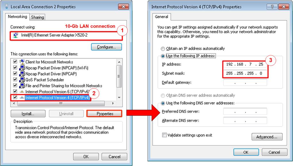
Figure 2‑1 Setting IP address for PC
1) Open Local Area Connection Properties of 10-Gb connection, as shown in the left window of Figure 2‑1.
2) Select �TCP/IPv4� and then click Properties.
3) Set IP address = 192.168.7.25 and Subnet mask = 255.255.255.0, as shown in the right window of Figure 2‑1.
2.2 Speed and Frame Setting
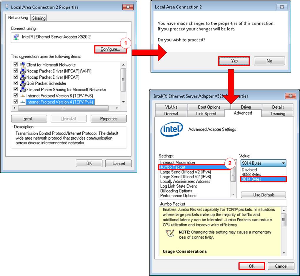
Figure 2‑2 Set frame size = jumbo frame
1) On Local Area Connection Properties window, click �Configure� and confirm to change the properties, as shown in the top side of Figure 2‑2.
2) On Advanced Tab, select �Jumbo Packet�. Set Value to �9014 Bytes� for Jumbo Frame or �Disabled� for non-Jumbo Frame, as shown in the bottom window of Figure 2‑2.
3) On Link Speed, select �10 Gbps Full Duplex� for running 10-Gigabit transfer test, as shown in Figure 2‑3.
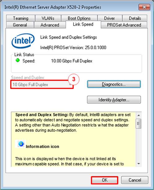
Figure 2‑3 Set link speed = 10 Gbps
4) On PROSet Advanced Tab, select �Performance Options� and click �Properties� button.
5) Set �Interrupt Moderation Rate� = OFF.

Figure 2‑4 Interrupt Moderation Rate
6) Select �Low Latency Interrupts� and click �Properties� button.
7) On �Low Latency Interrupts� window, select �Use Low Latency Interrupts� and click �OK� button.
8) Click �OK� button to save and exit all setting windows.
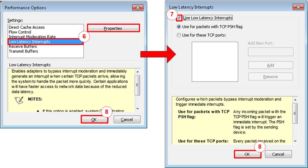
Figure 2‑5 Use Low Latency Interrupts
2.3 Power Option Setting
1) Open Control Panel and select Power Options as shown in the left window of Figure 2‑6.
2) Change setting to High Performance as shown in the right window of Figure 2‑6.
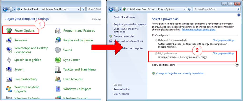
Figure 2‑6 Power options
2.4 Firewall Setting

Figure 2‑7 Firewall setting
1) Open Control Panel and select Windows Firewall.
2) Click �Turn Windows Firewall on or off�.
3) Select Turn off Firewall under Private and Public network settings.
4) Click OK button to confirm the setting.
3 Test menu
3.1 Display current parameter
Select �0� to show all current parameters using in the demo. There are two groups of the parameters, i.e., common parameters which are shared for all sessions and session parameters which are independent for each session.
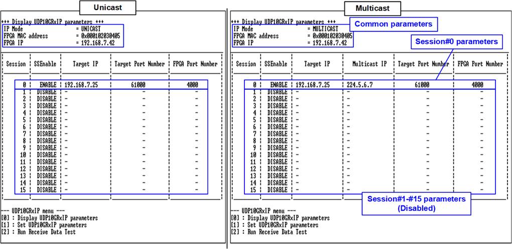
Figure 3‑1 Test result when running menu[0]
· Common parameter: There are three common parameters.
1) IP Mode : IP mode of UDP10GRx-IP - Unicast or Multicast.
Default value is Unicast mode
2) FPGA MAC address : 48-bit hex value to be MAC address of FPGA
3) FPGA IP : IP address of FPGA.
· Session parameter: There are four or five session parameters, depending on IP mode. The user sets session parameters for each session separately.
1) SSEnable : Enable each session. Default value enables only session#0 while other sessions are disabled.
2) Target IP : IP address of destination device. When running with one PC, this value is set by using IP address of 10 Gb Ethernet card on PC.
3) Multicast IP : Multicast IP address which is subscribed by UDP10GRx-IP.
Note: This parameter is displayed when running in Multicast mode only.
4) Target port number : Port number of the destination device which is set on TestPC.
5) FPGA port number : Port number of FPGA.
To change some parameters, menu[1] (Set UDP10GRxIP parameters) is selected.
3.2 Set UDP10GRxIP parameter
Select �1� to change IP parameters. After that, current parameters are displayed on the console. User enters �x� to use the same parameters or other keys to change some parameters. When finishing the step to get all parameters from the user, the session which has the updated parameters from the user must be disabled for re-loading the new parameters and then enabled for starting session initialization.
The parameters, set by the user, are updated when the input is valid. Otherwise, the value does not change. The description of each parameter is explained in the previous topic (3.1 Display current parameter). The parameters on the console are listed as follows.
· Common parameters
If some common parameters are updated, all sessions must be disabled before loading the new parameters to the IP. The valid range of each common parameter is described as follows.
1) IP Mode : Set �0� for running in Unicast mode or
�1� for running in Multicast mode.
2) FPGA MAC address : Set 12 digits of hex value. Add �0x� as a prefix for hex value.
3) FPGA IP : A set of four decimal digits is separated by �.�.
The valid range of each decimal digit is 0-255.
· Session parameters
The user is asked to set session parameters for session#0-session#15 respectively. Only the session that has the updated parameters is disabled for loading the new session parameters to the IP. After that, the updated session is re-enabled.
1) SSEnable : Set �0� to disable the session or �1� to enable the session.
2) Target IP : A set of four decimal digits is separated by �.�. The valid range of each decimal digit is 0-255.
3) Multicast IP : A set of four decimal digits is separated by �.�. The valid range of each decimal digit is 0-255.
Note: This parameter is valid when IP mode is Multicast mode.
4) Target port number : Valid range is 0-65535.
5) FPGA port number : Valid range is 0-65535.
Note: This parameter is valid when IP mode is Unicast mode.
The example to change the session parameters are displayed in Figure 3‑2.

Figure 3‑2 The example to set IP parameters for 16 sessions
After finishing parameter assignment, all parameters are displayed on the console. Next, the session which updates the parameters is disabled and then re-enabled. Finally, �IP initialization complete� is shown after finishing the initialization process, as shown in Figure 3‑3.
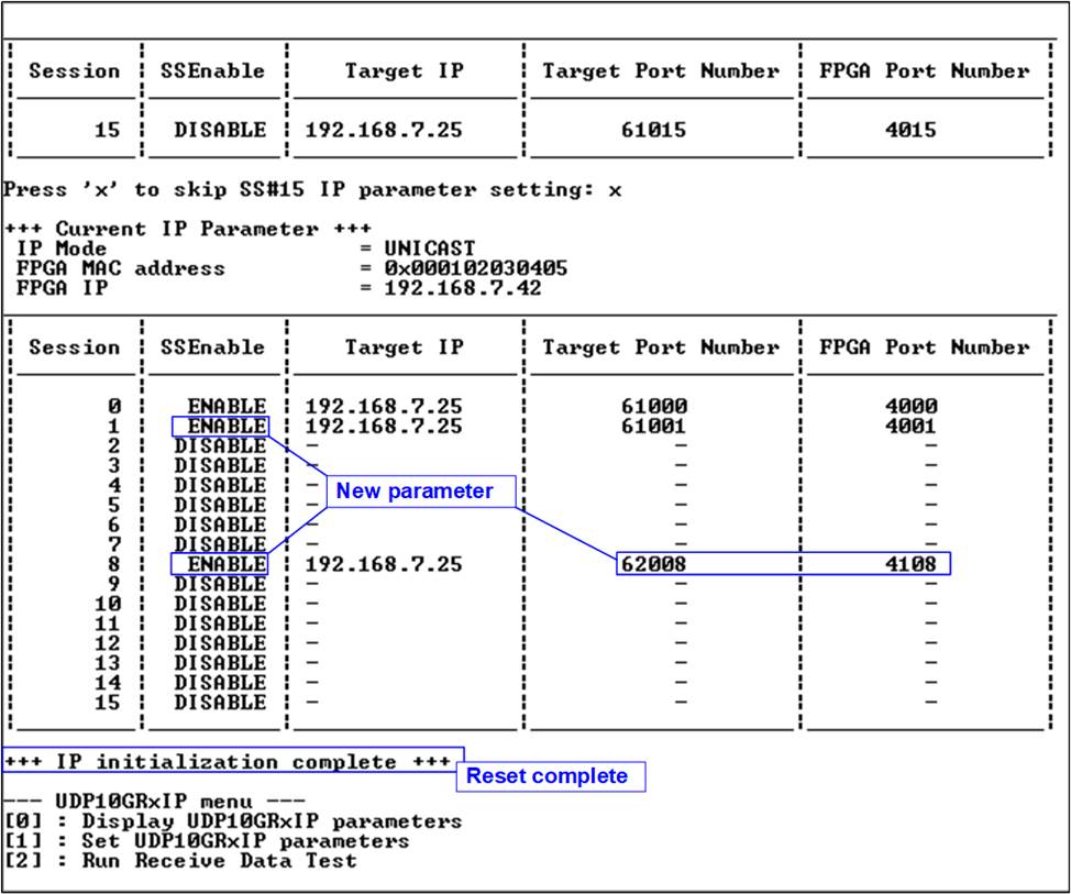
Figure 3‑3 Test result when running menu[1]
3.3 Receive Data Test (Unicast mode)
Select �3� to run receive data test on FPGA. The data is transferred data from TestPC which runs �trans_udp_multi� application. User sets test parameters on FPGA via FPGA console while test parameters of �trans_udp_multi� are set via Command prompt. This topic shows the example to run receive data test in Unicast mode while the next topic shows the example to run receive data test in Multicast mode.
1) On FPGA console, set two or three parameters under receive data test menu.
a) Input transfer size: Unit of transfer size of each session is byte. Valid value is 1 - 0xFFFF_FFFF_FFFF. The input is decimal unit when input only digit number. User adds �0x� to be a prefix for hexadecimal unit.
b) Input data verification mode: Set �0� to disable data verification or �1� to enable data verification.
c) Input SS#0-#15 Start pattern: Start pattern of test data is 32-bit incremental pattern. The start pattern of each session can be set independently. Valid value is 0 � 0xFFFF_FFFF. The input is decimal unit when input only digit number. User adds �0x� to be a prefix for hexadecimal unit.
Note: This input is displayed when data verification mode is enabled.
2) If all inputs are valid, the recommended parameters to run test application on PC are displayed. Next, �Wait data from Target ...� is displayed when the IP is ready to receive data from PC.
3) On Command prompt, set parameters following the recommended value. There are two steps to input the parameters. First step is running �trans_udp_multi� application with five common parameters as follows.
>> trans_udp_multi [SSNum] [IPMode] [Dir] [Bytelen] [Pattern]
a) SSNum : Input 1-16 for setting total number of sessions for sending the data
b) IPMode : Input �u� when running Unicast mode
c) Dir : Input �t� for sending test data to FPGA
d) Bytelen : Input the same value as �Input transfer size� of step 1a)
e) Pattern : Input the same value as �Input data verification mode� of step 1b)
Next step is setting five session parameters for each session as follows.
>> SS#0-#15: [FPGAIP] [FPGAPort] [PCIP] [PCPort] [StartPatt]
a) FPGAIP : Input the same value as FPGA IP address
b) FPGAport : Input the same value as FPGA port number of SS#0-#15
c) PCIP : Input the same value as target IP address of the session
d) PCPort : Input the same value as target port number of the session
e) StartPatt : Input the same value as �SS#0-#15 Start pattern� of step 1c)
4) After setting all parameters on the application completely, test application starts sending data to FPGA. During transferring data, current transfer size of every session is displayed on FPGA console (received size) and Command prompt (transmit size) every second.
5) �Receive data completed� is displayed on FPGA console after FPGA receives all data or timeout is found. Finally, total transfer size and performance are displayed on FPGA console (received performance) and Command prompt (transmit performance). If the test is finished by timeout condition, the warning message is displayed on FPGA console to show total amount of received data and the expected amount of received data. Finally, the latency time of UDP10GRx-IP and UDPRx16SS2AXI4 module are displayed.
The examples to run receive data test in many conditions in Unicast mode are displayed as follows.
Figure 3‑4 and Figure 3‑5 shows the example of receive data test by using one session with enabling and disabling data verification respectively. The left window is test result on FPGA console while the right window is test result on Command prompt. Some TestPCs shows the better performance when disabling data verification, comparing to enabling data verificaiton.
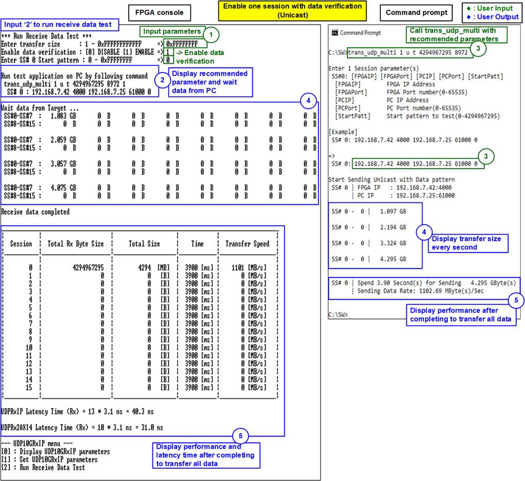
Figure 3‑4 Receive data test with data verification for one session (Unicast)
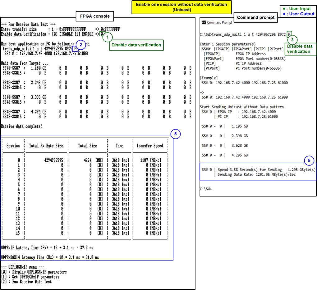
Figure 3‑5 Receive data test without data verification for one session (Unicast)
Figure 3‑6 and Figure 3‑7 show the result of receive data test when 16 sessions are enabled and the data are transferred to all sessions at the same time. Figure 3‑6 shows test parameters and the result on FPGA console while Figure 3‑7 shows the command and the result on Command prompt. All sessions enable data verification.
The results show the best performance for transferring data via 10 Gb Ethernet. The average speed of each session on FPGA console is about 77 MB/s. Therefore, total performance of 16 sessions is 1234 MB/s (77MB/s x 16).
Timer on FPGA console is shared for all sessions, so the result on FPGA console is similar for all sessions. However, Timer on Command prompt is run independently for each session. Therefore, the performance result in block (5) of Figure 3‑7 for each session may be different. It depends on CPU characteristic of TestPC to handle each session.

Figure 3‑6 Receive data test when enabling verification for 16 sessions on FPGA side (Unicast)

Figure 3‑7 Receive data test when enabling verification for 16 sessions on PC side (Unicast)
When running the real application, the IP may enable all sessions but only one session data is transferred at a time. Figure 3‑8 shows the example of receive data test when FPGA receives one session data from TestPC while sixteen sessions are enabled.
In the demo, the expected received length of all sessions set on FPGA is the same value. Therefore, the test of this condition is finished by timeout condition.
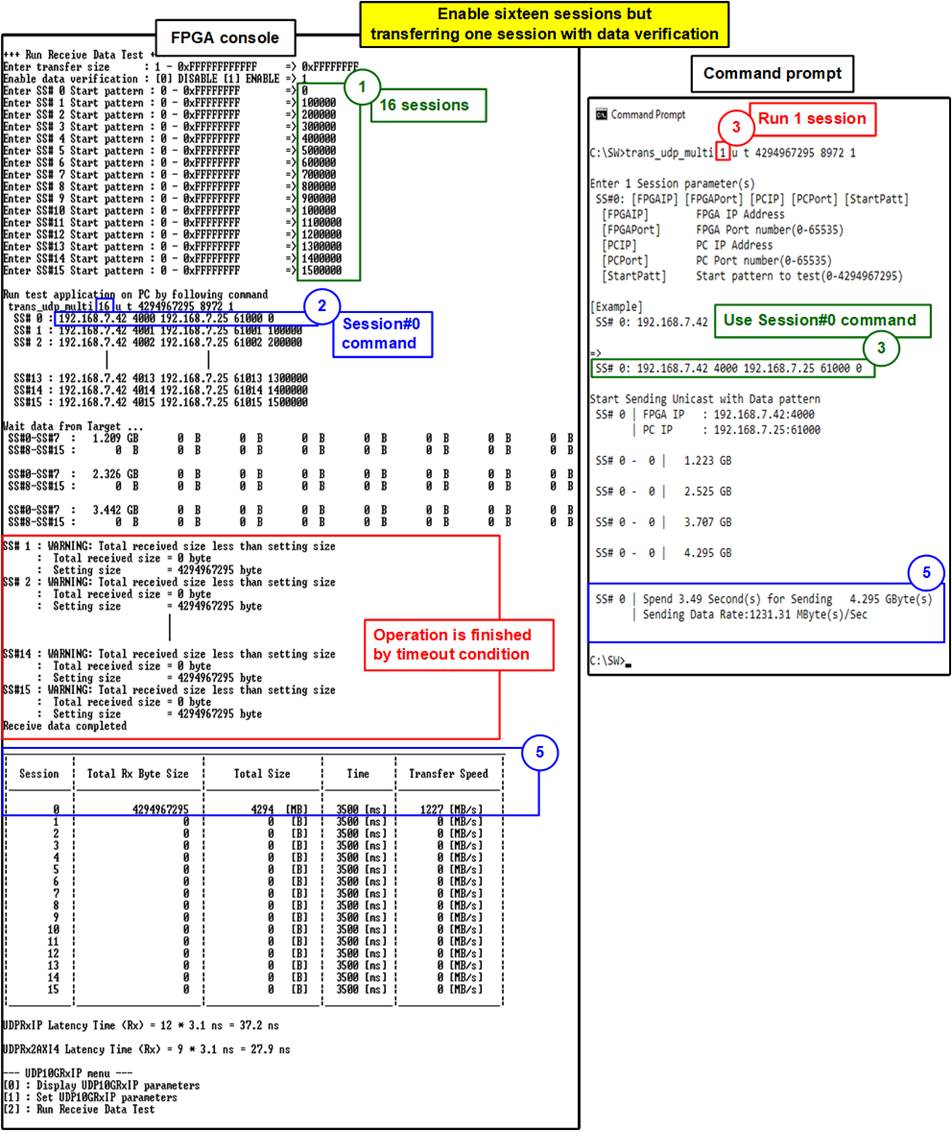
Figure 3‑8 Receive data test when enabling sixteen sessions
but transferring one session (Unicast)
The examples of error conditions when running receive data test are shown as follows.
Figure 3‑9 shows the message when there is no session enabled before running menu[2]. After that, the operation is cancelled and main menu is displayed.
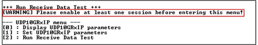
Figure 3‑9 Error when running receive data test without enabling the session
Figure 3‑10 - Figure 3‑12 show the examples when the input from user is invalid. �Out-of-range input� is displayed and the operation is cancelled.

Figure 3‑10 Error from invalid transfer size
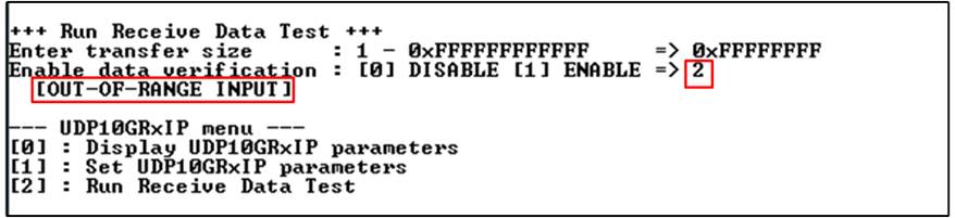
Figure 3‑11 Error from invalid data verification
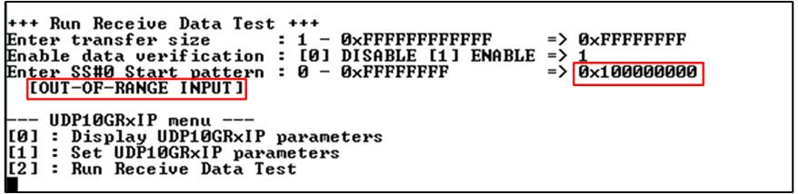
Figure 3‑12 Error from invalid start pattern
3.4 Receive Data Test (Multicast mode)
When running in Multicast mode, most steps of the test are similar to Unicast mode, but some parameters are different.
1) Set two or three parameters on FPGA console, similar to step 1) in the previous topic (Receive Data Test (Unicast mode)).
2) Wait until the message is displayed on FPGA console, similar to step 2) in the previous topic (Receive Data Test (Unicast mode)).
3) On Command prompt, set parameters following the recommended value. There are two steps to input the parameters. First step is running �trans_udp_multi� application with five common parameters as follows.
>> trans_udp_multi [SSNum] [IPMode] [Dir] [Bytelen] [Pattern]
a) SSNum : Input 1-16 for setting total number of sessions for sending the data
b) IPMode : Input �m� when running Multicast mode
c) Dir : Input �t� for sending test data to FPGA
d) Bytelen : Input the same value as �Input transfer size� of step 1a)
e) Pattern : Input the same value as �Input data verification mode� of step 1b)
Next step is receiving sixteen session parameters for each session as follows.
>> SS#0-#15: [McastIP] [McastPort] [TxPort] [StartPatt]
a) McastIP : Input the same value as Multicast IP address
b) McastPort : Input the same value as FPGA port number of SS#0-#15
c) TxPort : Input the same value as target port number of the session
d) StartPatt : Input the same value as �SS#0-#15 Start pattern� of step 1c)
4) After setting all parameters on the application completely, test application starts sending data to FPGA. During transferring data, current transfer size of every session is displayed on FPGA console (received size) and Command prompt (transmit size) every second.
6) �Receive data completed� is displayed on FPGA console after FPGA receives all data or timeout is found. Finally, total transfer size and performance are displayed on FPGA console (received performance) and Command prompt (transmit performance). If the test is finished by timeout condition, the warning message is displayed on FPGA console to show total amount of received data and the expected amount of received data. Finally, the latency time of UDP10GRx-IP and UDPRx2AXI4 module are displayed.
The examples to run receive data test in many conditions in Multicast mode are displayed as follows.
Figure 3‑13 and Figure 3‑14 shows the example of receive data test by using one session with enabling and disabling data verification respectively. The left window is test result on FPGA console while the right window is test result on Command prompt. Similar to Unicast, the performance when disabling data verification may show the better performance than enabling data verification.
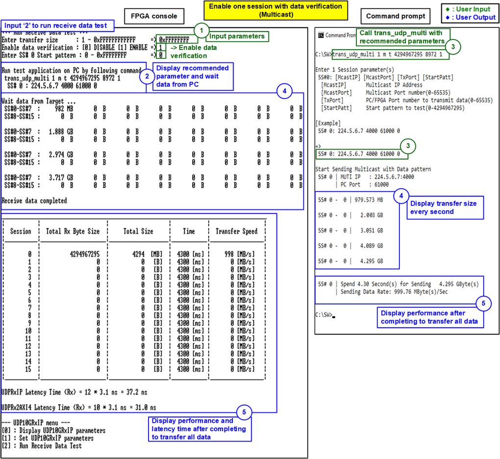
Figure 3‑13 Receive data test with data verification for one session (Multicast)

Figure 3‑14 Receive data test without data verification for one session (Multicast)
Figure 3‑15 and Figure 3‑16 show the result of receive data test when 16 sessions are enabled and the data are transferred to all sessions at the same time. Figure 3‑15 shows test parameters and the result on FPGA console while Figure 3‑16 shows the command and the result on Command prompt. All sessions enable data verification.
The results show the best performance for transferring data via 10 Gb Ethernet. The average speed of each session on FPGA console is about 77 MB/s. Therefore, total performance of 16 sessions is 1234 MB/s (77MB/s x 16).
Similar to Unicast mode, Timer on FPGA console is shared for all sessions, so the result on FPGA console is similar for all sessions. While Timer on Command prompt is run independently for each session. Therefore, the performance result in block (5) of Figure 3‑16 for each session may be different. It depends on CPU characteristic of TestPC to handle each session.
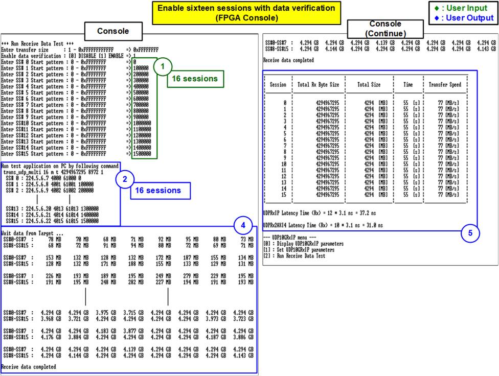
Figure 3‑15 Receive data test when enabling verification for 16 sessions on FPGA side (Multicast)
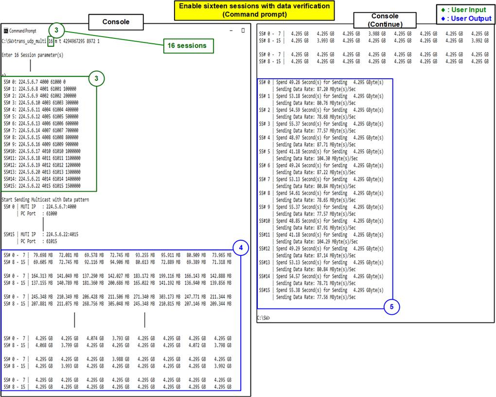
Figure 3‑16 Receive data test when enabling verification for 16 sessions on PC side (Multicast)
When running the real application, the IP may enable all sessions but only one session data is transferred at a time. Figure 3‑17 shows the example of receive data test when FPGA receives one session data from TestPC while sixteen sessions are enabled.
In the demo, the expected received length of all sessions set on FPGA is all the same value. Therefore, the test of this condition is finished by timeout condition.

Figure 3‑17 Receive data test when enabling sixteen sessions
but transferring one session (Multicast)
4 Revision History
|
Revision |
Date |
Description |
|
1.0 |
24-Nov-21 |
Initial version release |