FPGA Setup for UDP10GRx-IP demo
Rev1.1 4-Jul-23
This document describes how to setup FPGA board and prepare the test environment for running 4-session demo or 16-session demo by UDP10GRx-IP. The demo is designed for transferring data from 10G Ethernet card that is installed on TestPC to the FPGA development board by running “trans_udp_multi” (test application) on TestPC. The application sends UDP packet to the FPGA development board via 1-16 sessions. The hardware including UDP10GRx-IP receives UDP data with or without data verification. The user interface for controlling the hardware via Serial console, run on TestPC. More details of the demo are described as follows.
1 Environment Setup
Please prepare following test environment.
1) FPGA development board: ZCU102 or KCU116 board
2) PC with 10 Gigabit Ethernet support or 10 Gigabit Ethernet card
3) 10 Gb Ethernet cable:
· 10 Gb SFP+ Passive Direct Attach Cable (DAC) which has 1-m or less length
· 10 Gb SFP+ Active Optical Cable (AOC)
· 2x10 Gb SFP+ transceivers (10G BASE-R) with optical cable (LC to LC, Multimode)
4) Two micro USB cables for FPGA programming and Serial console monitoring, connecting between FPGA board and PC
5) “trans_udp_multi.exe” which is test application provided by Design Gateway, prepared on PC
6) Serial console software such as TeraTerm installed on PC. The setting on the console is Baudrate=115,200, Data=8-bit, Non-parity, and Stop=1.
7) Vivado tool for programming FPGA, installed on PC
Note: Example of test environment is shown as follows.
[1] 10G Network Adapter: Intel X520-DA2
[2] 10-Gigabit SFP+ AOC (AOC-S1S1-001)
https://www.10gtek.com/10gsfp+aoc
[3] PC: Motherboard ASUS Z170-K, 32 GB RAM, 64-bit Windows10 OS

Figure 1‑1 UDP10GRx-IP demo on ZCU102
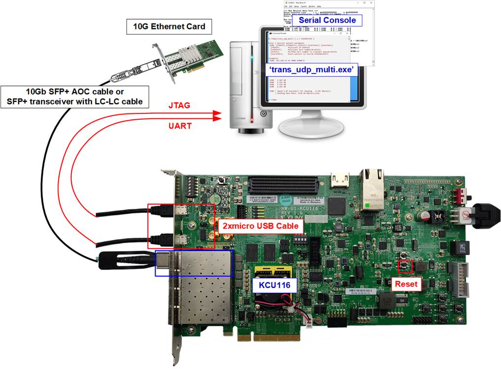
Figure 1‑2 UDP10GRx-IP demo on KCU116
2 FPGA board setup
1) For ZCU102, check DIPSW and jumper setting on FPGA board as shown in Figure 2‑1.
· Insert jumper to J16 to enable Tx SFP+
· Set SW6=all ONs to use USB-JTAG.
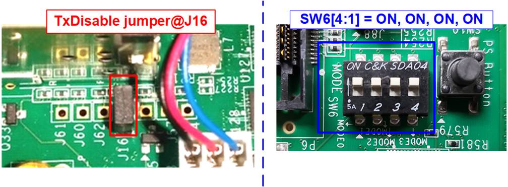
Figure 2‑1 ZCU102 board setting
2) Connect two micro USB cables between FPGA board and PC for JTAG programming and USB UART.
3) Connect power supply to FPGA development board.
4) Connect 10 Gb Ethernet cable (10 Gb SFP+ DAC (Length<1m), AOC or SFP+ transceiver with LC-LC cable) between FPGA board and PC, as shown in Figure 2‑2.
a) On ZCU102 board, use the top-right SFP+ channel.
b) On KCU116 board, use the left SFP+ channel.
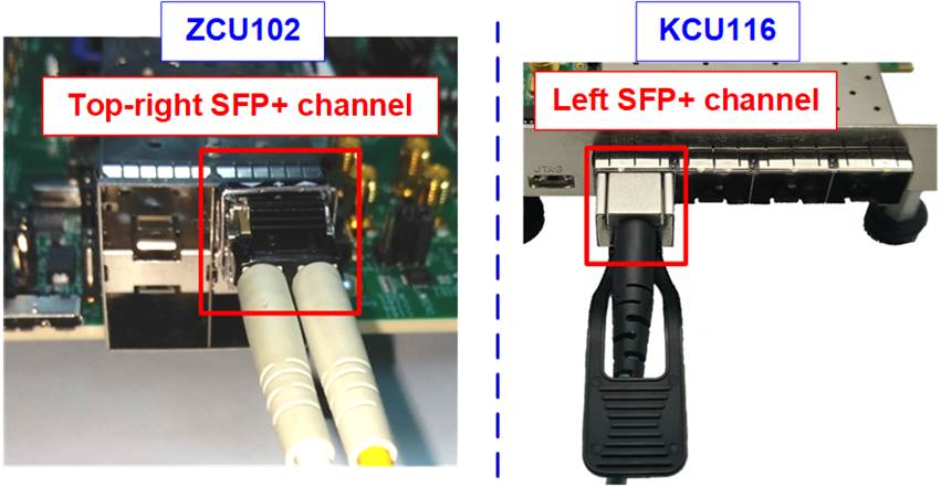
Figure 2‑2 Connect SFP+ cable on ZCU102 or KCU116 board
5) Power on FPGA board.
6) Open Serial console. When connecting FPGA board to PC, many COM ports from FPGA connection are detected and displayed on Device Manager.
a) On ZCU102 board, select COM port number of Interface0 to be Serial console.
b) On KCU116 board, select Standard COM port to be Serial console.
On Serial console, use following setting: Baud rate=115,200, Data=8-bit, Non-Parity, and Stop = 1.
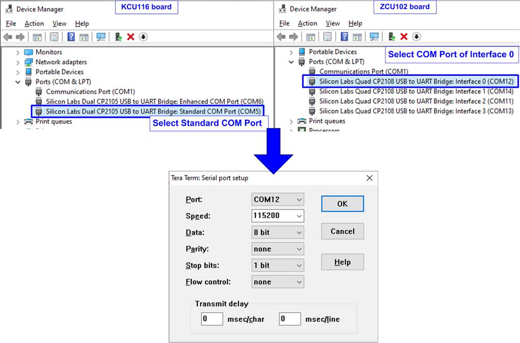
Figure 2‑3 COM port number for Serial console
7) Download configuration file and firmware to FPGA board.
a) On KCU116 board, use Hardware Manager on Vivado tools, as shown in Figure 2‑4.

Figure 2‑4 Program FPGA by Vivado
b) On ZCU102 board, open Vivado TCL shell and change current directory to download folder which includes demo configuration file and command script file for download. After that, run “udp10grxtest_zcu102.bat/udp10grx16sstest_zcu102.bat” to configure FPGA and download firmware, as shown in Figure 2‑5.
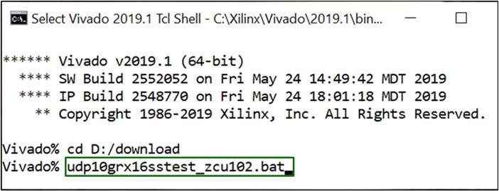
Figure 2‑5 Example command script for downloading ZCU102 by Vivado tool
8) After finishing downloading configuration file, default common parameter is displayed on the console.
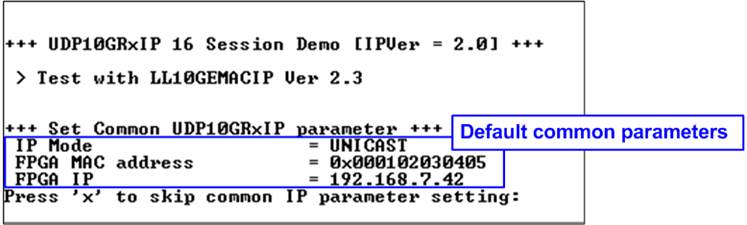
Figure 2‑6 Display default common parameter
9) User enters ‘x’ to use default common parameters and then enters ‘x’ to use default session parameters which enable only session#0 by Unicast mode, as shown in Figure 2‑7. Otherwise, user enters other keys (not ‘x’) to change common or session parameters. More details to change parameters are described in demo instruction document. After finishing system initialization, main menu is displayed on the Serial console.
Note: Transfer performance in the demo depends on Test PC resource in Test platform.

Figure 2‑7 Input parameter setting and display main menu
3 Revision History
|
Revision |
Date |
Description |
|
1.0 |
23-Jun-20 |
Initial version release |
|
1.1 |
23-Nov-21 |
Add KCU116 board and 16-session demo |