exFAT2 IP Core for Gen4 Datasheet
Write File and Read File commands in Parallel
Abort Write and Read file Commands with Customized (mu)NVMe IP

Core Facts |
|
|
Provided with Core |
|
|
Documentation |
Reference Design Manual Demo Instruction Manual |
|
Design File Formats |
Encrypted file |
|
Instantiation Templates |
VHDL |
|
Reference Designs & Application Notes |
Vivado Project, See Reference Design Manual |
|
Additional Items |
Demo on VCK190, KCU116 |
|
Support |
|
|
Support Provided by Design Gateway Co., Ltd. |
|
Design Gateway Co.,Ltd
E-mail: ip-sales@design-gateway.com
URL: design-gateway.com
Features
· Access NVMe SSD as an exFAT system without CPU and external memory required
· Simple user interface
· Direct connection to DG NVMe IP for Gen4 or muNVMe IP for Gen4
· Simultaneous SSD access for 1-2 users
· Achieve comparable write/read performance, compared to raw data format
· Support device capacities: 8 Gigabytes* – 64 Petabytes*
*Gigabyte means 1024x1024x1024 bytes, while Petabyte means 1024x1024x1024x1024x1024 bytes
· Support for 512-byte LBA unit only
· Command support:
· User#0 (Main user): Format, Secure Format, Write file, Read file, Read file info, and Shutdown
· User#1 (Sub user): Read file and Read file info
· Support eleven file sizes* - 32MB, 64MB, 128MB, 256MB, 512MB, 1GB, 2GB, 4GB, 8GB, 16GB, and 32GB. Some file sizes are not available for certain device capacities.
· Support for abort feature to halt data transfer (customized feature of the (mu)NVMe IP)
· Reference design available on VCK190 and KCU116 boards with AB17-M2FMC or AB18-PCIeX16 adapter board
· Customized services available for the following features:
· Increasing user channels
· Updating supported file sizes and file names
· Additional commands such as Delete file
Table 1: Example Implementation Statistics (Versal)
|
Family |
Example Device |
User Count |
Fmax (MHz) |
CLB Regs |
CLB LUTs |
Slice |
BRAM Tile |
URAM |
Design Tools |
|
Versal AI Core |
XCVC1902-VSVA2197-2MP-E-S |
1 |
375 |
3701 |
3918 |
836 |
8 |
- |
Vivado2022.1 |
|
2 |
4204 |
4271 |
901 |
8 |
Note: Actual logic resource dependent on percentage of unrelated logic
Table 2: Example Implementation Statistics (UltraScale+)
|
Family |
Example Device |
User Count |
Fmax (MHz) |
CLB Regs |
CLB LUTs |
CLB |
BRAM Tile |
URAM |
Design Tools |
|
Kintex-Ultrascale+ |
XCKU5P-FFVB676-2E |
1 |
375 |
3741 |
3708 |
772 |
8 |
- |
Vivado2022.1 |
|
2 |
4242 |
4082 |
813 |
8 |
Note: Actual logic resource dependent on percentage of unrelated logic
 Applications

Figure 1: exFAT2 IP for Gen4 Application
The exFAT2 IP enables two users to concurrently write and read files simultaneously from the same SSD with full transfer performance, similar to raw data access. By integrating the exFAT2 IP with the muNVMe IP and TOE100G IP, as illustrated in Figure 1, a comprehensive solution for real-time logging data streams from external devices, such as high-speed A/D converters, is achieved. This solution facilitates storing data to NVMe Gen4 SSD while simultaneously providing an additional user channel for reading data from the SSD, while data logging operations continue. By connecting the read interface to the TOE100G IP, this system presents a solution for data logging with real-time monitoring capabilities.
General Description
The exFAT2 IP Core provides a solution to implement a file system without the need for both CPU and external memory. Utilizing pure hardwired logic achieves full performance for writing and reading data in the exFAT file system, matching the same performance as raw data access. To utilize the exFAT2 IP, it must be connected to the NVMe IP solutions from Design Gateway, NVMe IP or muNVMe IP for Gen4, to access data as an exFAT file system instead of raw data mode.
The user interface of the exFAT2 IP closely resembles that of the (mu)NVMe IP, ensuring ease of use. However, it updates the index parameters from physical numbers to file numbers to specify the starting position for writing and reading data, as well as to specify the transfer size. The command interface of the exFAT2 IP is designed to support six commands: Format, Secure Format, Write file, Read file, Read file info, and Shutdown. While User#0 (Main) supports all six commands, User#1 (Sub) supports two commands: Read File and Read File Info. The data interface of the exFAT2 IP aligns with that of the (mu)NVMe IP, utilizing the general FIFO interface. Ensure that the clock domain for operating the exFAT2 IP matches that of the (mu)NVMe IP.
The exFAT2 IP requires additional parameters during the execution of Format, Secure Format, and Write commands. These parameters include the created date and created time, which are utilized to set the created date and time of empty directories or new files. Furthermore, when executing the Format or Secure Format command, an extra parameter, File size, must be specified to initialize the storage. This parameter can be chosen from eleven values: 32MB, 64MB, 128MB, 256MB, 512MB, 1GB, 2GB, 4GB, 8GB, 16GB, and 32GB. However, some file sizes may not be available for specific device capacities. For further information regarding the supported file sizes for each device capacity, please refer to Table 3.
Table 3: Supported file size for each device capacity
|
Device capacity |
32MB(2) |
64MB(2) |
128MB(2) |
256MB(2) |
512MB(2) |
1GB(2) |
2GB(2) |
4GB(2) |
8GB(2) |
16GB(2) |
32GB(2) |
|
8 GB - 16 GB(1) |
Yes |
Yes |
Yes |
Yes |
Yes |
Yes |
Yes |
Yes |
No |
No |
No |
|
16 GB – 32 GB(1) |
Yes |
Yes |
Yes |
Yes |
Yes |
Yes |
Yes |
Yes |
Yes |
No |
No |
|
32 GB – 64 GB(1) |
Yes |
Yes |
Yes |
Yes |
Yes |
Yes |
Yes |
Yes |
Yes |
Yes |
No |
|
64 GB – 512 TB(1) |
Yes |
Yes |
Yes |
Yes |
Yes |
Yes |
Yes |
Yes |
Yes |
Yes |
Yes |
|
512 TB – 2 PB |
No |
Yes |
Yes |
Yes |
Yes |
Yes |
Yes |
Yes |
Yes |
Yes |
Yes |
|
2 PB – 8 PB(1) |
No |
No |
Yes |
Yes |
Yes |
Yes |
Yes |
Yes |
Yes |
Yes |
Yes |
|
8 PB – 32 PB(1) |
No |
No |
No |
Yes |
Yes |
Yes |
Yes |
Yes |
Yes |
Yes |
Yes |
|
32 PB – 64 PB(1) |
No |
No |
No |
Yes |
Yes |
Yes |
Yes |
Yes |
Yes |
Yes |
Yes |
Note:
(1) The upper limit of device capacity must be less than this value. For example, when the device capacity is 512 TB, the user checks the supported file size from the row corresponding to 512 TB – 2 PB, not from 64GB – 512 TB.
(2) MB means 1024x1024 bytes. GB means 1024x1024x1024 bytes.
TB means 1024x1024x1024x1024 bytes. PB means 1024x1024x1024x1024x1024 bytes.
Upon completing the Format operation for both Standard and Secure types, the file size for accessing an NVMe SSD is a fixed value. This file size cannot be updated without executing the (Secure) Format command. The (Secure) Format command is required as the first command to initialize the SSD for first-time usage. Upon completion, 512 empty directories will appear as the operation result, including DIR000, DIR001, …, and so forth up to DIR1FF. The three digits following DIR are assigned hexadecimal values, ranging from 0 to F. These three digits can be decoded to decimal values, such as DIR0FF referring to Directory number 255.
All 512 directories are created by the (Secure) Format operation for every device capacity. However, the maximum number of files in each directory (DirCap) depends on the device capacity, and the maximum number of actually used directories also depends on the specified file size, as shown in Table 4.
The new file name generated during the execution of the Write file command consists of seven hexadecimal digits. The first file name is 0000000.BIN, which is stored in DIR000. If the user requests multiple files in the command, subsequent files, such as 0000001.BIN and 0000002.BIN, are stored in the same directory (DIR000) until the maximum capacity for each directory is reached, as indicated by the DirCap signal. Once this limit is reached, the additional new files created will be stored in subsequent directories, starting with DIR001.
Table 4: The maximum number of files per directory (DirCap)
|
Device capacity |
DirCap[19:0] |
Minimum file size |
Used directory |
|
8 GB - 32 GB(1) |
256 (0x00100) |
32MB |
DIR000 - DID003 |
|
32 GB – 128 GB(1) |
512 (0x00200) |
32MB |
DIR000 - DIR007 |
|
128 GB – 512 GB(1) |
1024 (0x00400) |
32MB |
DIR000 – DIR00F |
|
512 GB – 2 TB(1) |
2048 (0x00800) |
32MB |
DIR000 – DIR01F |
|
2 TB – 8 TB(1) |
4096 (0x01000) |
32MB |
DIR000 – DIR03F |
|
8 TB – 32 TB(1) |
8192 (0x02000) |
32MB |
DIR000 – DIR07F |
|
32 TB – 128 TB(1) |
16384 (0x04000) |
32MB |
DIR000 – DIR0FF |
|
128 TB – 512 TB(1) |
32768 (0x08000) |
32MB |
DIR000 – DIR1FF |
|
512 TB – 2 PB(1) |
65536 (0x10000) |
64MB |
DIR000 – DIR1FF |
|
2 PB – 8 PB(1) |
131072 (0x20000) |
128MB |
DIR000 – DIR1FF |
|
8 PB – 32 PB(1) |
262144 (0x40000) |
256MB |
DIR000 – DIR1FF |
|
32 PB – 64 PB(1) |
524288 (0x80000) |
256MB |
DIR000 – DIR1FF |
Note: (1) The upper limit of device capacity
must be less than this value. For example, when the device capacity is 32 GB, the
user checks the value of DirCap from the row corresponding to 32 GB – 128 GB,
not from 8 GB – 32 GB.
Functional Description
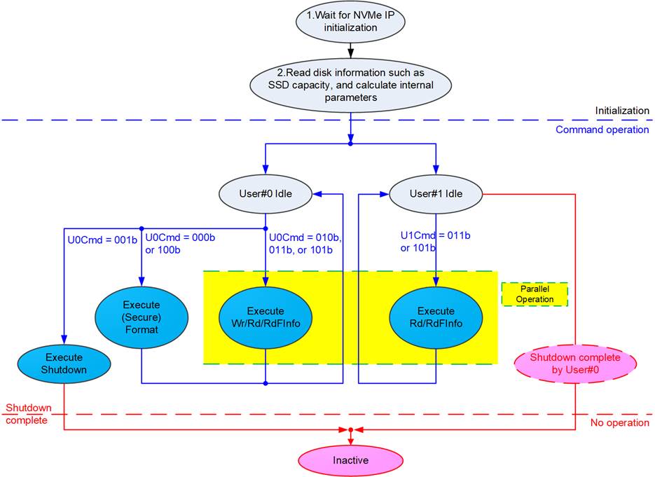
Figure 2: exFAT2 IP Operation
The operation flow of the exFAT2 IP is divided into three phases: Initialization, Command operation, and No operation, as shown in Figure 2. Firstly, the initialization phase is handled by User#0 I/F. During this phase, User#1 I/F remains inactive until the initialization phase concludes. The initialization step includes:
1) exFAT2 IP waits until the (mu)NVMe IP completes NVMe SSD initialization.
2) exFAT2 IP sends Identify command to the (mu)NVMe IP to retrieve SSD information such as SSD capacity and Secure erase command support. Subsequently, file information for this SSD is updated, including current file size (DiskFSize) and the number of files (DiskFnum). Upon completing the Identify command, the exFAT2 IP becomes ready to receive new commands from each user. User#0 supports six commands: Format, Secure Format, Write file, Read file, Read file info, and Shutdown, while User#1 supports two commands: Read file and Read file info.
Once the initialization process concludes, all user interfaces remain idle and prepared to receive commands from the user. Commands of each User I/F can be requested in parallel, except for (Secure) Format and Shutdown commands. All users must return to an Idle state before (Secure) Format or Shutdown command is requested through User#0 I/F.
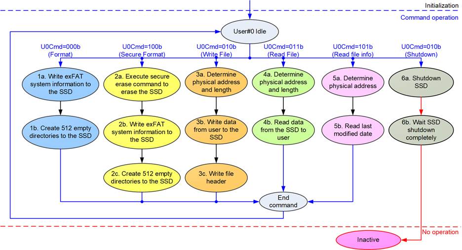
Figure 3: Operation Flow for User#0 Command
For a new SSD that has never been formatted by an exFAT2 IP, the first command issued by the user must be the (Secure) Format, initializing the SSD. The sequence of exFAT2 IP operation is as follows.
1) The Format command must be firstly executed for the uninitialized SSD with minimal data written to the SSD, so the operation time for this command is much shorter than the Secure Format command. Once completing the command, 512 empty directories are created in the SSD and the number of files available in the SSD, indicated by DiskFnum signal, is reset to zero.
2) The Secure Format command is an alternative command for executing the Format operation, initializing the SSD. In comparison to the Format command, this command erases all data in the SSD using the Secure Erase command to ensure that the data cannot be recovered for security reasons. This command may take a longer time to complete the operation. The results after completing this command are similar to the Format command: the creation of 512 empty directories and the reset value of DiskFnum to zero.
3) To initiate the Write file command, the user sets the first file name (U0FName) and the number of written files (U0FLen). The exFAT2 IP reads these inputs, determines the physical address and transfer size for configuration to the (mu)NVMe IP, and asserts the Write file command request. Subsequently, data transfer occurs from the users to the SSD via the exFAT2 IP and (mu)NVMe IP until completion. Finally, the exFAT2 IP writes the file entries for all written files.
Note:
i) Since the file entries are written as the last step, all written files can be lost or corrupted if the system powers down immediately before completing the writing of all file entries.
ii) Ensure that the input values are within the valid range for initiating the Write file command.
4) To initiate the Read file command, the user must specify the first file name and the number of read files to determine the physical address and transfer size for configuration to the (mu)NVMe IP and assert the Read command request. Subsequently, data is returned from the SSD to the users via the exFAT2 IP and (mu)NVMe IP until completion.
Note: The exFAT2 IP supports the Abort function for Write file and Read file commands, allowing the cancellation of ongoing Write file and Read file commands. However, this function can be enabled only when integrating with customized (mu)NVMe IP. For further information, please contact our sales team.
5) To initiate the Read file info command, the user specifies the file name to retrieve its information. Upon receiving the command request, the exFAT2 IP determines the physical address of the SSD to be used as input for the (mu)NVMe IP. Once the raw data is returned, the exFAT2 IP decodes the received data and displays the last modified date of the selected file to the user.
6) The last command before powering down the system must be the Shutdown command, ensuring the SSD is powered down in a proper sequence. Without the Shutdown command execution may result in the loss of data integrity on the SSD. Upon completion of the Shutdown command, the exFAT2 IP, (mu)NVMe IP, and SSD enter the Inactive state and cease to accept any further commands until a reset signal is asserted to the IPs.
exFAT2 IP
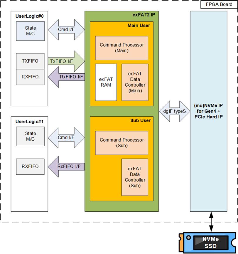
Figure 4: exFAT2 IP Block Diagram
As shown in Figure 4, the exFAT2 IP logics are divided to interface separately with User#0 (Main user) and User#1 (Sub user) in parallel. The Main user, supporting all six commands, consists of three submodules: Command Processor, exFAT Data Controller, and exFAT RAM. On the other hand, the Sub user, supporting Read file and Read file info commands, consists of two submodules: Command Processor and exFAT Data Controller. The Command Processor is responsible for processing command requests from each user, while the exFAT Data Controller manages data transfer with users in both directions. Since the Sub user supports only Read command, its data interface operates in a single direction, from the exFAT2 IP to the user. The exFAT RAM module is exclusively available in the Main user to store the system parameters required for the exFAT file system. Further details of each submodule are described as follows.
· Command Processor
This module serves as the core processor, controlling the sequence of packet transfer during the execution of each command. It is responsible for setting and monitoring signals from other modules, including exFAT RAM (only for Main user) and exFAT Data Controller. Additionally, it encompasses various logics for computing system parameters of the exFAT file system based on user inputs. These parameters include (mu)NVMe IP input parameters and constant values assigned to the system data in the SSD. Several parameters are dependent on file size and SSD capacity.
· exFAT RAM
This RAM stores the system parameters for the exFAT file system. It has a size of 512x256-bit, implemented by BlockRAM.
· Data Controller
Though the data interface with the user logic and the (mu)NVMe IP utilize FIFO interfaces, the actual data transfer of each interface differs. The data interface with the user logic is employed to transfer raw data within each file. In contrast, the data interface with the (mu)NVMe IP encompasses various data types, such as raw data, file entries, and system parameters stored in the exFAT RAM.
DG (mu)NVMe IP for Gen4
The exFAT2 IP is designed for directly integration with the DG NVMe IPs for Gen4, including NVMe IP (for a single user) or muNVMe IP (for multiple users). Both NVMe IPs serve as the host controllers, facilitating access to NVMe Gen4 SSD via PCIe interface. Detailed information about the NVMe IP and muNVMe IP for Gen4 can be found at the following links.
Single user solution: NVMe IP datasheet
https://dgway.com/products/IP/NVMe-IP/dg_nvme_ip_data_sheet_g4_en/
Multiple user solution: muNVMeIP datasheet
https://dgway.com/products/IP/NVMe-IP/dg_munvme_ip_data_sheet_g4_xilinx/
User Logic
The user interface of the exFAT2 IP is designed for simplicity, allowing users to implement it using a small state machine for parameter assignment and sending command requests to the exFAT2 IP. Additionally, two FIFOs are integrated for transferring raw data of each file for each user interface (User#0 or User#1). However, the exFAT2 IP reference design includes a CPU to provide added flexibility in setting test parameters and monitoring the test progress using a Serial console.
Core I/O Signals
Table 5 provides descriptions of all I/O signals for exFAT2 IP.
Table 5: Core I/O Signals
|
Signal |
Dir |
Description |
|
Clock and Reset |
||
|
RstB |
In |
Synchronous reset signal on the Clk domain, active low. De-assert to 1b after the Clk signal is stable. |
|
Clk |
In |
User clock, output from the same clock source for the user clock of (mu)NVMe IP. The frequency must be greater than or equal to the PCIeClk frequency, the output from the PCIe hard IP (250 MHz for 4-lane PCIe Gen4) |
|
User Interface (Command) |
||
|
U0FSize[3:0] |
In |
File size stored in the SSD, which is fixed value for using in (Secure) Format command. It can be set to eleven values: 0000b: 32MB, 0001b: 64MB, 0010b: 128MB, 0011b: 256MB, 0100b: 512MB, 0101b: 1GB, 0110b: 2GB, 0111b: 4GB, 1000b: 8GB, 1001b: 16GB, 1010b: 32GB This input is exclusively utilized for executing the (Secure) Fomat command. Note: 1 MB equals 1024x1024 bytes and 1 GB equals 1024x1024x1024 bytes |
|
U0FDateY[6:0] |
In |
Year in the created date, counted from 1980 (For example, FDateY=39 represents year 2019). Note: U0FDateY, U0FDateM, U0FDateD, U0FTimeH, U0FTimeM and U0FTimeS are utilized to set the created time of new files or directories during the execution of the (Secure) Format or Write file command. |
|
U0FDateM[3:0] |
In |
Month in the created date. Valid range is from 1 to 12 (1=Jan, 2= Feb, etc.). Please refer to the note in the U0FDateY description. |
|
U0FDateD[4:0] |
In |
Day in the created date. Valid range is from 1 to 31. Please refer to the note in the U0FDateY description. |
|
U0FTimeH[4:0] |
In |
Hour in the created time. Valid range is from 0 to 23. Please refer to the note in the U0FDateY description. |
|
U0FTimeM[5:0] |
In |
Minute in the created time. Valid range is from 0 to 59. Please refer to the note in the U0FDateY description. |
|
U0FTimeS[4:0] |
In |
Seconds in the created time, multiplied by 2. Valid range is from 0 to 29 (1=2, 2=4, etc.). Please refer to the note in the U0FDateY description. |
|
U0Cmd[2:0] |
In |
User Command for User#0 I/F. Valid when U0Req=1b. The possible values are 000b: Format, 001b: Shutdown, 010b: Write file, 011b: Read file, 100b: Secure Format, 101b: Read file info Note: Secure Format requires SuppSecureFmt to be set to 1b to confirm SSD support for Secure Erase. |
|
U1Cmd[2:0] |
In |
User Command of User#1 I/F. valid when U1Req=’1’. 011b: Read file, 100b: Read file info |
|
U0-1FName[26:0] |
In |
The first file name used to execute commands: Write file, Read file, or Read file info. These file names follow a specific naming rules: 0=’0000000.BIN’, 1=’0000001.BIN’, and so on. The valid range is from 0 to (TotalFCap – 1). During the execution of the Write file command for User#0, this value must not exceed the DiskFnum value. When this value is set equal to DiskFnum, the new file name created in the new command request will continue from the latest written file name. Otherwise, the new files from the new command request will overwrite the completely written file from the previous Write file command request. |
|
Signal |
Dir |
Description |
|
User Interface (Command) |
||
|
U0-1FLen[26:0] |
In |
The total number of files requested in this command, used in Write file and Read file commands. The valid range is from 1 to (TotalFCap – U0-1FName). |
|
U0-1Req |
In |
Set to 1b to send a new command request and de-assert to 0b after the IP starts the operation by setting U0-1Busy to 1b. This signal can only be asserted when the exFAT2 IP is in Idle state, indicating by U0-1Busy being set to 0b. The input parameters required for the corresponding command request must be valid and stable while U0-1Req is set to 1b. The command parameters include U0FSize, U0-1Cmd, U0-1FName, U0-1FLen, U0FDateYMD, and U0FTimeHMS. |
|
U0-1Busy |
Out |
Set to 1b when the IP is busy for executing the command from User#0/#1. |
|
U0-1FInfo[31:0] |
Out |
Indicate the modified date and time of the requested file upon the completion of Read file info command. [4:0] – Seconds, multiplied by 2. Valid range is from 0 to 29 (1=2, 2=4, etc.). [10:5] – Minute. Valid range is from 0 to 59. [15:11] – Hour. Valid range is from 0 to 23. [20:16] – Date. Valid range is from 1 to 31. [24:21] – Month. Valid range is from 1 to 12 (1=Jan, 2= Feb, etc.). [31:25] – Year counted from 1980, counted from 1980. |
|
U0-1Error |
Out |
Error flag. Asserted to 1b when U0-1ErrorType is not equal to 0. Once error has been resolved, the user can clear this flag by asserting reset signal to both (mu)NVMe IP and exFAT2 IP. |
|
U0-1ErrorType[7:0] |
Out |
Error status. The error status of User#0 is mapped to bits[2:0], while the error status of User#1 is mapped to only bit[0]. The remaining bits are reserved for future usage. [0] – An error detected by the (mu)NVMe IP. Further information can be read from U0-1NVMeErrorType[31:0]. [1] – An error occurs when the SSD capacity is out of supported range, 8 GB – 64 PB. [2] – An error occurs when the LBA unit of SSD is not equal to 512 bytes. |
|
U0-1NVMeErrorType [31:0] |
Out |
An error status output from the (mu)NVMe IP. Further details are described in the description of UserErrorType signal for the NVMe IP or U0-1ErrorType signal for the muNVMe IP. |
|
U0TestPin[63:0], U1TestPin[31:0] |
Out |
Reserved for DG Internal use. |
|
SuppSecureFmt |
Out |
Indicate whether the SSD supports the Secure Format command (0b: not supported, 1b supported). This value becomes valid after the completion of IP initialization. |
|
TotalFCap[26:0] |
Out |
Maximum number of files that can be stored on the SSD. Note: 1) TotalFCap, DiskFsize, and DiskFnum become valid after the completion of exFAT2 IP initialization, indicated by U0Busy being set to 0b. 2) TotalFCap, DiskFSize, and DiskFnum are invalid if the SSD has never been formatted by exFAT2 IP. |
|
DirCap[19:0] |
Out |
Maximum number of files that can be stored per directory. This value becomes valid after the completion of IP initialization. |
|
DiskFsize[3:0] |
Out |
File size currently used in the SSD. Please refer to the note in the TotalFCap description. |
|
DiskFnum[26:0] |
Out |
Total count of files stored in the SSD. This signal is also updated after the completion of Write file command. Please refer to the note in the TotalFCap description. |
Signal |
Dir |
Description |
|
User Interface (Command) |
||
|
DiskFnumCur[26:0] |
Out |
Current total count of files within the SSD. This signal is updated during the execution of the Write file command. Upon completion of the Write file command, this value is updated to DiskFnum. It can be used to monitor the completed written files, which are ready for reading via User#1 while User#0 is executing the Write file command. Note: This signal is computed based on the value of NVMe0CompWrLen. Therefore, it becomes invalid when using a single user with NVMe IP, not muNVMe IP. |
|
IPVesion[31:0] |
Out |
IP version number. |
|
TimeOutSet[31:0] |
In |
Timeout value to wait for completion from SSD. The time unit is equal to 1/(Clk frequency). When TimeOutSet is equal to 0, Timeout function is disable. This value is generally set to 2 secs. |
|
User Interface (Data) |
||
|
U0-1FifoWrCnt[15:0] |
In |
Write data counter for the Receive FIFO. Used to monitor the FIFO full status. When the FIFO becomes full, data transmission from the Read file command temporarily halts. If the data count of FIFO is less than 16 bits, the upper bits should be padded with 1b to complete the 16-bit count. |
|
U0-1FifoWrEn |
Out |
Asserted to 1b to write data to the Receive FIFO when executing the Read file command. |
|
U0-1FifoWrData [255:0] |
Out |
Write data bus of the Receive FIFO. Valid when U0-1FifoWrEn is set to 1b. |
|
U0FifoRdCnt[15:0] |
In |
Read data counter for the Transmit FIFO. Used to monitor the amount of data stored in the FIFO. If the counter indicates an empty status, the transmission of data packets for the Write file command temporarily pauses. When the data count of FIFO is less than 16 bits, the upper bis should be padded with 0b to complete the 16-bit count. |
|
U0-1FifoEmpty |
In |
Unused for this IP. |
|
U0FifoRdEn |
Out |
Asserted to 1b to read data from the Transmit FIFO when executing the Write file command. |
|
U0FifoRdData[255:0] |
In |
Read data returned from the Transmit FIFO. Valid in the next clock after U0FifoRdEn is asserted to 1b. |
Signal |
Dir |
Description |
|
(mu)NVMe IP User Interface (Further details of each signal are described in the datasheet of the (mu)NVMe IP Note: 1) When using a single user with NVMe IP, the NVMe0<signal_name> of this interface is connected to User<signal_name> of NVMe IP. For example, NVM0Cmd[2:0] is linked to UserCmd[2:0] of NVMe IP. 2) When using multiple users with muNVMe IP, the NVM0-1<signal_name> of this interface are connected to U0-1 <signal_name> of muNVMe IP. For example, NVMe0-NVMe1Cmd[2:0] are linked to U0-1Cmd[2:0] of muNVMe IP. |
||
|
NVMeTimeOutSet [31:0] |
Out |
TimeOutSet of the (mu)NVMe IP. |
|
NVMeLBASize[47:0] |
In |
LBASize of the (mu)NVMe IP. |
|
NVMeLBAMode |
In |
LBAMode of the (mu)NVMe IP. |
|
NVMe0-1Cmd[2:0] |
In |
UserCmd of the NVMe IP or U0-1Cmd of the muNVMe IP. |
|
NVMe0-1Addr[47:0] |
Out |
UserAddr of the NVMe IP or U0-Addr of the muNVMe IP. |
|
NVMe0-1Len[47:0] |
Out |
UserLen of the NVMe IP or U0-1Len of the muNVMe IP. |
|
NVMe0-1Req |
Out |
UserReq of the NVMe IP or U0-1Req of the muNVMe IP. |
|
NVMe0-1Busy |
In |
UserBusy of the NVMe IP or U0-1Busy of the muNVMe IP. |
|
NVMe0-1Error |
In |
UserError of the NVMe IP or U0-1Error of the muNVMe IP. |
|
NVMe0-1ErrorType [31:0] |
In |
UserErrorType of the NVMe IP or U0-1ErrorType of the muNVMe IP. |
|
NVMe0-1FifoWrCnt [15:0] |
Out |
UserFifoWrCnt of the NVMe IP or U0-1FifoWrCnt of the muNVMe IP. |
|
NVMe0-1FifoWrEn |
In |
UserFifoWrEn of the NVMe IP or U0-1FifoWrEn of the muNVMe IP. |
|
NVMe0-1FifoWrData [255:0] |
In |
UserFifoWrData of the NVMe IP or U0-1FifoWrData of the muNVMe IP. |
|
NVMe0FifoRdCnt[15:0] |
Out |
UserFifoRdCnt of the NVMe IP or U0FifoRdCnt of the muNVMe IP. |
|
NVMe0FifoEmpty |
Out |
UserFifoEmpty of the NVMe IP or U0FifoEmpty of the muNVMe IP. |
|
NVMe0FifoRdEn |
In |
UserFifoRdEn of the NVMe IP or U0FifoRdEn of the muNVMe IP. |
|
NVMe0FifoRdData [255:0] |
Out |
UserFifoRdData of the NVMe IP or U0FifoRdData of muNVMe IP. |
|
NVMe0CompWrLen [47:0] |
In |
U0CompWrLen of the muNVMe IP. Set by zero value when connecting with the NVMe IP. If this signal is set to zero, DiskFNumCur, U0AbortFName, and U0AbortCurWrLen become invalid. |
|
NVMe0CtmSubm DW0-15[31:0] |
Out |
CtmSubmDW0-15 of the NVMe IP or U0CtmSubmDW0-15 of the muNVMe IP. |
|
IdenWrEn |
In |
Connected to IdenWrEn of the (mu)NVMe IP. |
|
IdenWrDWEn[7:0] |
In |
Connected to IdenWrDWEn of the (mu)NVMe IP. |
|
IdenWrAddr[7:0] |
In |
Connected to IdenWrAddr of the (mu)NVMe IP. |
|
IdenWrData[255:0] |
In |
Connected to IdenWrData of the (mu)NVMe IP. |
Signal |
Dir |
Description |
|
Additional Interface for Abort function Note: This function can be enabled when using with the customized muNVMe IP for Gen4. For further information, please contact our sales team. |
||
|
U0-1Abort |
In |
Assert to 1b for a single clock cycle to abort the ongoing Write file/Read file command operation. The completion of the abort function is indicated by U0-1Busy being set to 0b. |
|
U0AbortFName[26:0] |
Out |
Indicate the last written file name upon the completion of the abort operation for Write file command. |
|
U0AbortCurWrLen [25:0] |
Out |
Indicate the completely written data size of the last written file name in 512-byte units upon the completion of the abort operation for Write file command. |
|
NVMe0-1Abort |
Out |
Connected to U0-1Abort of muNVMe IP. |
Timing Diagram
Initialization
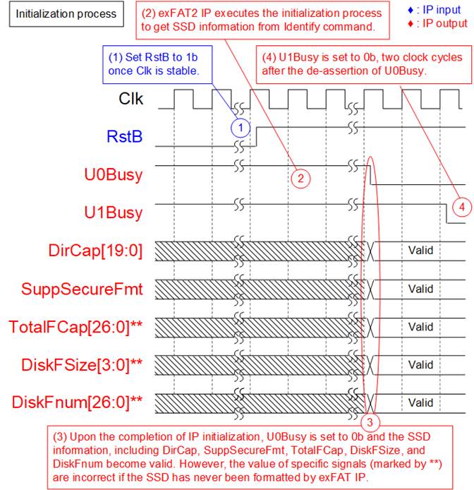
Figure 5: exFAT2 IP Initialization
During the initialization process of the exFAT2 IP, the following steps are executed.
1) Once the Clk signal is stable, set RstB to 1b to initiate the initialization process of the exFAT2 IP.
2) During initialization, the exFAT2 IP sends the Identify command to the (mu)NVMe IP to retrieve SSD information, which is necessary to compute the system parameters for the exFAT file system.
3) Upon completion of the initialization process, U0Busy is set to 0b, and status signals such as DirCap, SuppSecureFmt, TotalFCap, DiskFSize, and DiskFnum become valid for reading. Subsequently, the user can send commands to the exFAT2 IP via the User#0 I/F.
Note: The values of TotalFCap, DiskFSize, and DiskFnum depend on the file size configured during the (Secure) Format command, so these signal values are applicable only when the SSD has been formatted by the exFAT2 IP.
4) The User#1 I/F becomes ready to receive new commands two clock cycles after the readiness of the User#0 I/F, indicated by U1Busy being set to 0b.
Format command
If the SSD has never been initialized by the exFAT2 IP, executing the Format or Secure Format command is necessary as the first command. Otherwise, the Format operation is utilized for following objectives: deleting all files or changing the file size of the SSD. In cases where data security is concerned, it is recommended to use the Secure Format command instead of the Format command. The Format command is optimized to complete the operation quickly, which may result in some data in the SSD not being deleted.
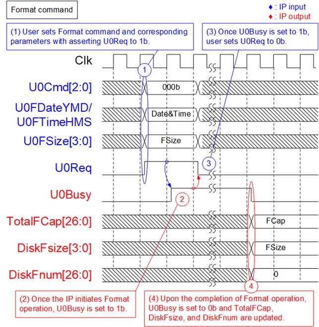
Figure 6: Timing diagram of Format command
During the Format command operation, the following steps are executed.
1) The user sets U0Cmd to 000b (Format) along with its corresponding parameter values (U0FDateYMD: Created data, U0FTimeHMS: Created time, and U0FSize: File size), and asserts U0Req to 1b.
2) The exFAT2 IP initiates the Format operation and sets U0Busy to 1b. The system parameters are computed based on the user-specified parameters and the SSD capacity.
3) Once U0Busy is set to 1b, U0Req can be de-asserted to 0b, indicating the completion of this command request.
4) Upon the completion of the Format command, U0Busy is set to 0b. The SSD is initialized by writing the file system information and creating 512 empty directories (DIR000 – DIR1FF). The values of TotalFCap, DiskFsize, and DiskFnum become valid for reading. DiskFnum is reset to 0 to indicate that the SSD is empty. The created date and time of empty directories are configured by the value of U0FDateYMD and U0FTimeHMS.
Secure Format command
The Secure Format command performs the same function as the Format command but employs the Secure Erase command to erases all data. This ensures that all data is thoroughly cleaned and cannot be recovered. In certain SSDs, employing the Secure Erase command can restore the transfer performance of the SSD, which may have degraded after storing a large amount of data.
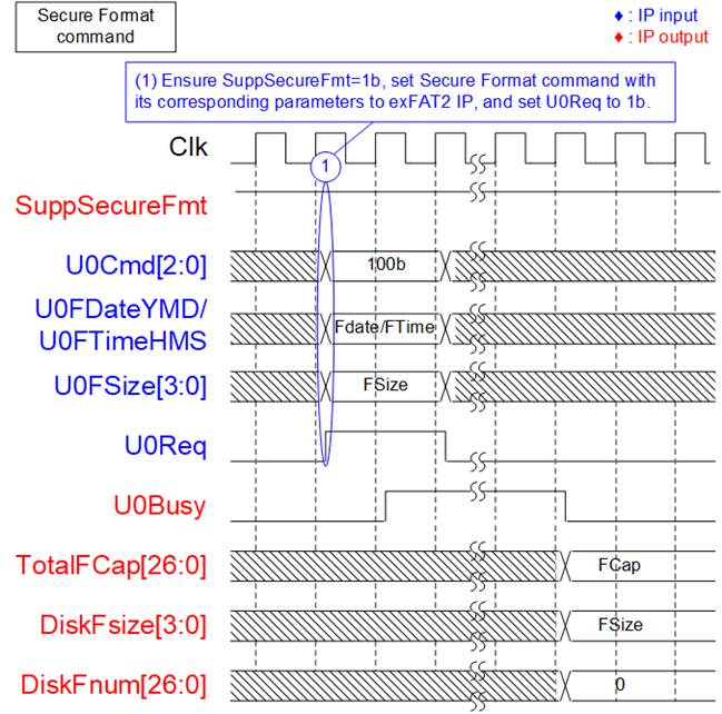
Figure 7: Timing diagram of Secure Format command
During the Secure Format command operation, the following steps are executed.
1) Verify that the SSD supports the Secure Format command by checking if SuppSecureFmt is set to 1b. If supported, proceed with steps 1) – 4) of the Format command, but set U0Cmd to 100b (Secure Format) instead. Note that the operation time of the Secure Format command is longer compared to the Format command.
Write File command
The Write file command can be requested via User#0 I/F. During the execution of the Write file command, raw data from User#0 data interface is written to the SSD. Without overwritten the available file in the SSD, the file name assigned to U0FName must set by the value of DiskFnum signal. If the SSD is empty, the DiskFnum value equals zero.
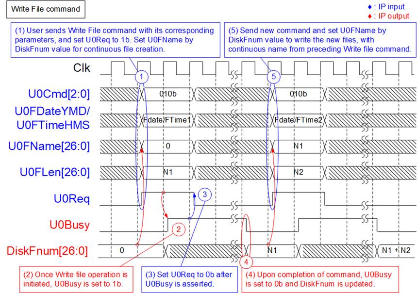
Figure 8: Timing diagram of User#0 Control Interface for Write file command
To execute two consecutive Write file command requests, the following steps are processed.
1) The user reads DiskFnum and assigns the read value to U0FName for generating the new file name, continuous from the preceding Write file operation. The user sets U0Cmd to 010b along with its corresponding parameter values (U0FDateYMD: Created date, U0FTimeHMS: Created time, U0FName: Name of the first written file, and U0FLen: Number of written files) and asserts U0Req to 1b. U0FName should be equal to DiskFnum to create new file name, which is the next value from the latest name. U0FLen must not be exceed (TotalFCap – U0FName). As shown in Figure 8, U0FName is equal to 0 when running the first Write file command to an empty SSD.
Note:
i) Setting U0FName value exceeding the value of DiskFnum results in exFAT2 IP malfunction.
ii) If U0FName value is less than DiskFnum, the files of the preceding Write file command will be overwritten by the new data.
2) The exFAT2 IP asserts U0Busy to 1b, indicating the initiation of the Write file command.
3) Once U0Busy is set to 1b, the user sets U0Req to 0b to clear the command request. Data is transferred from User#0 I/F to the SSD until completion.
4) U0Busy is de-asserted to 0b upon completion of the Write file command. DiskFnum value is updated to be equal to (U0FName + U0FLen). The created date and time of new files are configured by the values of FDataYMD and FTimeHMS.
5) Without overwritten data from the preceding Write file command, the value of U0FName for the subsequent Write file command must be equal to the value of U0FName.
If N1+N2 does not exceed DirCap value, all files from both Write file command can be stored in the first directory (DIR000), as illustrated in Figure 9.
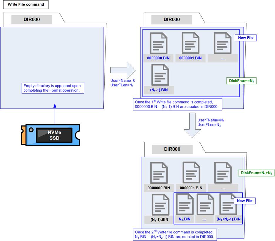
Figure 9: New files created upon completion of the Write file command
The first file name from the first Write file command is 0000000.BIN, and the last file name from the second Write file command is (N1 + N2 – 1).BIN. Each file name is assigned using seven hexadecimal digits.
During executing the Write file command, the User#0 data interface transmits data to the exFAT2 IP until completion of the command. Similar to the data interface of the (mu)NVMe IP, the data is transferred as 512-byte block size, using 16 clock cycles of 256-bit data size.
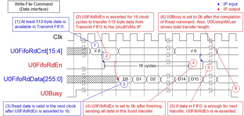
Figure 10: Transmit FIFO Interface for User#0 Write file command
The sequence for transmitting data via User#0 data interface is as follows.
1) Verify that U0FifoRdCnt[15:4] is not equal to zero, indicating that at least 512-byte of data are available for transfer.
2) The IP asserts U0FifoRdEn to 1b for 16 clock cycles to retrieve 512 bytes of data from the Transmit FIFO.
3) U0FifoRdData becomes valid in the next clock cycle after asserting U0FifoRdEn to 1b, and 16 sets of 256-bit data are continuously transferred.
4) After reading the 16th data (D15), U0FifoRdEn is de-asserted to 0b.
5) Steps 1) – 4) are reiterated to transfer the next 512 bytes of data until the total amount of data matches the specified transfer size in the command (U0FLen).
Note: In case of multiple users via muNVMe IP, during the execution of the Write file command, DiskFnumCur is updated to indicate the number of completed written file to the SSD.
6) Once all data is completely transferred, U0Busy is de-asserted to 0b.
The total data size for transmission can be computed as U0FLen multiplied by the file size. For example, if U0FLen = N1, the total amount of 256-bit data is equal to N1 x (file size in bytes / 32).
Read File command
The Read file command can be requested via both User#0 and User#1 I/Fs. During the execution of the Read file command, raw data from the SSD is transmitted to the respective User data interface. It is essential to ensure that the sum of U0FName and U0FLen (for User#0) or U1FName and U1FLen (for User#1) does not exceed the DiskFnum value to retrieve valid data, instead of dummy data. Figure 11 illustrates an example using the User#1 I/F. The same functions are designed for both User#0 and User#1 I/Fs.
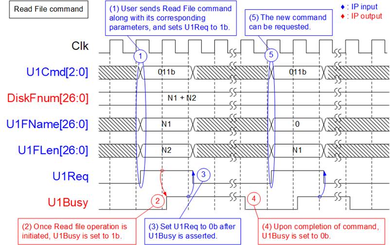
Figure 11: Timing diagram of User#1 Control Interface for Read file command
To execute the Read file command request, the following steps are processed.
1) The user sets U1Cmd to 011b along with its corresponding parameter values (U1FName: Name of the first read file, and U1Len: Number of read files) and asserts U1Req to 1b. It is crucial to ensure that the value of (U1FName + U1Len) does not exceed DiskFnum.
2) The exFAT2 IP asserts U1Busy to 1b, indicating the initiation of the Read file command.
3) Once U1Busy is set to 1b, the user sets U1Req to 0b to clear the command request. Data is transferred from the SSD to the User#1 I/F until completion.
4) U1Busy is de-asserted to 0b upon completion of the Read file command.
5) The user can then send a new command request to the exFAT2 IP.
An example of the User#1 Data interface during the execution of Read file command is illustrated in Figure 12.
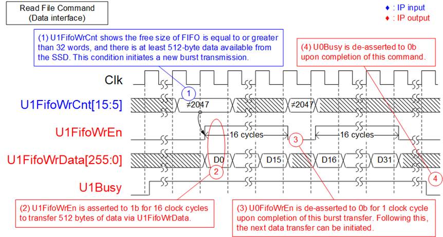
Figure 12: Receive FIFO Interface for User#1 Read file command
The sequence for receiving data via the User#1 data interface is as follows.
1) Before initiating a new burst transmission, the exFAT2 IP checks U1FifoWrCnt[15:5] to verify that there is sufficient free space available in the Receive FIFO#1, indicated by the condition U1FifoWrCnt[15:5]≠all 1 or 2047. Also, the IP waits until the amount of received data from the SSD reaches at least 512 bytes. Once both conditions are satisfied, the new burst transmission begins.
2) The IP asserts U1FifoWrEn to 1b for 16 clock cycles to transfer 512 bytes of data from the SSD to the User#1 I/F.
3) Upon completion of the transfer of 512-byte data, U1FifoWrEn is de-asserted to 0b for one clock cycle. If there is additional data remaining to be transferred, repeat steps 1) – 3) until the total data size matches the specified transfer size in the command (U1FLen).
4) Once all data has been completely transferred, U1Busy is de-asserted to 0b.
The total data size for reception can be computed as U1FLen multiplied by the file size. For example, if U1FLen = N1, the total amount of 256-bit data is equal to N1 x (file size in bytes / 32).
Write File and Read File commands in Parallel
The user can issue command requests simultaneously to both the User#0 I/F and User#1 I/F, except for the Format, Secure Format, or Shutdown command. Figure 13 illustrates an example of executing the Write file command on the User#0 I/F and the Read file command on the User#1 I/F simultaneously. Parallel operation must be facilitated using the muNVMe IP, where DiskFnumCur becomes valid for monitoring the progress of the Write file command before its completion.
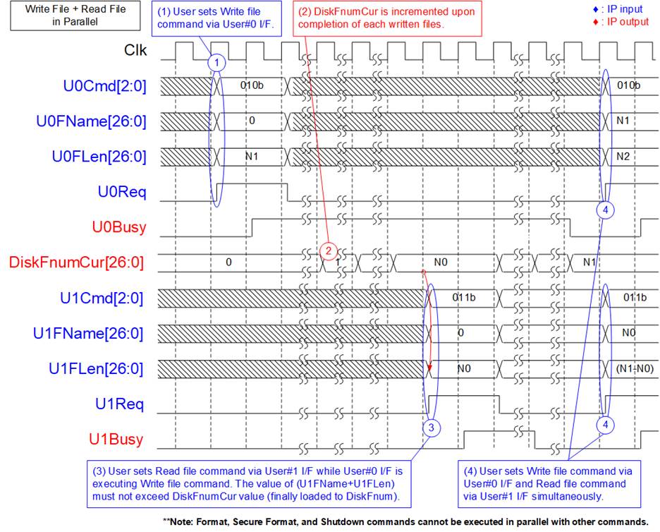
Figure 13: Control Interface timing diagram when executing command simultaneously
1) The User#0 I/F initiates the Write file command, setting U0FName to zero to create new files on an empty SSD. The DiskFnumCur value is initially zero for the empty SSD.
2) During the execution of the Write file command, DiskFnumCur is incremented to indicate the completion of each file written to the SSD.
3) Let’s assume DiskFnumCur equals N0, indicating the SSD contains N0 files. The User#1 I/F can then send a Read file command to retrieve all N0 files from the SSD, setting U1FName to 0 and U1FLen to N0. It is crucial at this stage to ensure that the value of (U1FName + U1FLen) does not exceed the DiskFnumCur value.
4) Upon completion of the User#0 I/F operation, both DiskFnumCur and DiskFnum are updated to N1. Subsequently, new command requests for both the User#0 I/F and User#1 I/F can be sent.
Read File Info command
In certain applications, the SSD records data until it reaches full capacity. Without executing the Format command, new data is written to the SSD from the beginning, starting with ‘0000000.BIN’. In such cases, it becomes necessary to distinguish files resulting from preceding Write file commands from those resulting from the latest Write file command. To achieve this, the user must assign different values for the created date and time for preceding and latest Write file commands.
To retrieve the created/modified date and time of the file, the user can issue a Read File Info command and specify the requested file name via both the User#0 I/F and User#1 I/F. Figure 14 illustrates an example of sending a Read file info command via the User#1 I/F.
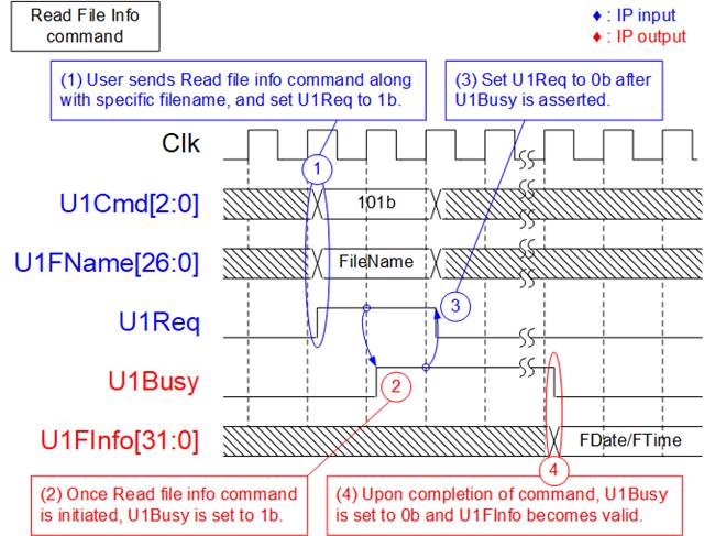
Figure 14: Timing diagram of User#1 Read File Info command
1) The user sets U1Cmd to 101b along with the corresponding parameter value (U1FName: Name of the requested file) and asserts U1Req to 1b. It is crucial to ensure that the value of U1FName does not exceed DiskFnum.
2) The exFAT2 IP asserts U1Busy to 1b, indicating the initiation of the Read file info command.
3) Once U1Busy is set to 1b, the user sets U1Req to 0b to clear the command request.
4) U1Busy is de-asserted to 0b upon completion of the Read file info command. U1FInfo becomes valid, indicating the created/modified date and time of the requested file.
Shutdown command
The Shutdown command is the final command to be sent before the system is powered down. It ensures that any data stored in the SSD’s internal cache is properly written to the flash memory before the shutdown process completes. Once the shutdown operation finishes, the exFAT2 IP, (mu)NVMe IP, and SSD enter an inactive state. If the SSD is powered down without executing the Shutdown command, any remaining data in the internal cache may be lost.
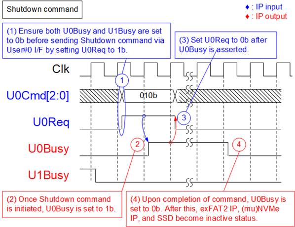
Figure 15: Timing diagram of Shutdown command
To execute the Shutdown command request, the following steps are processed.
1) Ensure that both U0Busy and U1Busy are set to 0b, indicating Idle status. The user sets U0Cmd to 010b and asserts U0Req to 1b.
2) The exFAT2 IP asserts U0Busy to 1b, indicating the initiation of the Shutdown command.
3) Once U0Busy is set to 1b, the user sets U0Req to 0b to clear the command request.
4) U0Busy is de-asserted to 0b upon completion of the Shutdown command. Subsequently, the exFAT2 IP becomes inactive.
Error
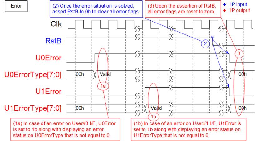
Figure 16: Timing diagram when an error occurs
If an error occurs during the initialization process or while executing certain commands, the U0-1Error flag is set to 1b. To identify the specific type of error, refer to the U0-1ErrorType, which corresponds to an error flag number. If bit[0] of U<i>ErrorType is set to 1b (where ‘i’ is the user index), the error is triggered by the (mu)NVMe IP error. In such cases, further details about the NVMe error type can be examined via the U<i>NVMeErrorType signal (where ‘i’ is the user index). The U0-1Error flag is reset exclusively by the RstB signal. Once the issue is resolved, assert RstB to 0b to clear the error flag.
exFAT2 IP Restrictions
1) An NVMe SSD connected to the exFAT2 IP must be formatted and written exclusively by the exFAT2 IP. Other host systems are permitted only for read-access.
2) The file size of all files stored in the SSD is configured by U0FSize during the execution of the (Secure) Format command. Upon completion of the Format operation, the size of the written file is fixed at this configured value. Additionally, the maximum number of files per directory and the maximum number of files for this SSD are displayed to the user output as fixed values. To change the file size, the (Secure) Format command must be executed.
3) Table 4 illustrates the relationship between the DirCap signal and the SSD capacity. User can determine the directory name from the file name using the following equation:
DIR Name = (<FileName>/DirCap) – 1.
For instance, if the SSD capacity is 100G, DirCap equals 512 and the file names stored in each directory are listed as shown in Table 6.
Table 6: The mapping table between file name and directory name
|
File name |
Directory name |
|
0000000.BIN – 00001FF.BIN |
DIR000 |
|
0000200.BIN – 00003FF.BIN |
DIR001 |
|
0000400.BIN – 00005FF.BIN |
DIR002 |
|
0000600.BIN – 00007FF.BIN |
DIR003 |
|
0000800.BIN – 00009FF.BIN |
DIR004 |
|
0000A00.BIN – 0000BFF.BIN |
DIR005 |
|
0000C00.BIN – 0000DFF.BIN |
DIR006 |
|
0000E00.BIN – 0000FFF.BIN |
DIR007 |
4) In Write file command, the newly written file is subsequent to the previously written file by setting U0FName to be equal to DiskFnum. If other values are set, the following situations may occur.
a) If U0FName exceeds DiskFnum, a maloperation will occur. The new files will be lost, and the DiskFnum value will be incorrect.
b) If U0FName is less than DiskFnum, the specified files of the preceding Write file command will be overwritten by the data transfer during the current Write file command. Additionally, if the sum of U<i>FName + U<i>FLen (where ‘i’ is a user index) is less than the DiskFnum value, the DiskFnum value will not be updated.
Abort Write and Read file Commands with Customized (mu)NVMe IP
In specific applications where continuous data streaming is required, specifying the exact total transfer size during the initiation the Write file and Read file commands may not be feasible. The default (mu)NVMe IP does not support cancelling Write and Read operations before completion. Consequently, an abort request for write and read operations in the (mu)NVMe IP is offered as a customized feature. For further information, please contact our sales department.
Each user interface provides U<i>Abort for sending an abort request; where ‘i’ refers to the user index. The Abort function of the specified user is initiated by asserting U<i>Abort for a single clock cycle. Following this, the completion of the abort operation can be indicated by U<i>Busy being set to 0b; where ‘i’ refers to the user index. The timing diagrams illustrating the cancellation of Write file and Read file commands using the Abort signal are presented in Figure 17 and Figure 18.
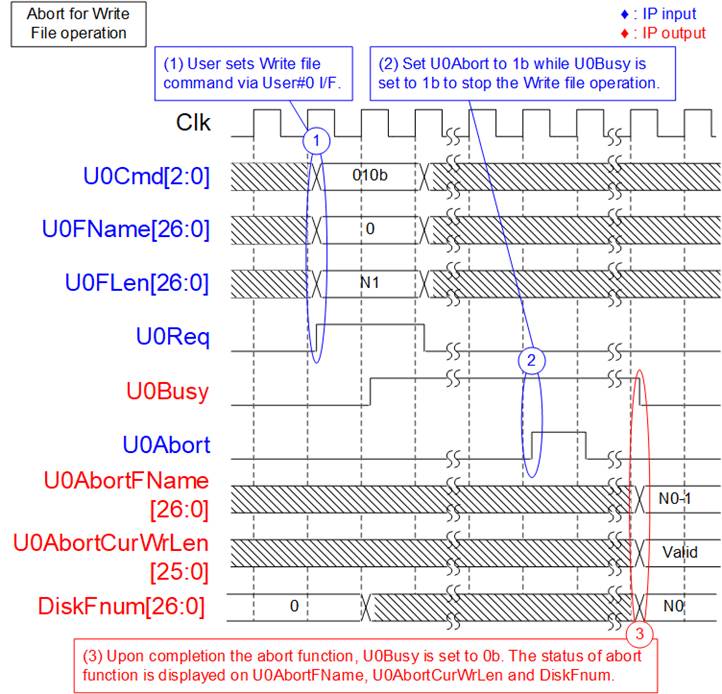
Figure 17: Timing diagram of abort during User#0 Write file command
The operation details of the abort function for Write file operation via User#0 I/F are as follows.
1) The User#0 I/F initiates the Write file command, setting U0FName to zero to create new files on an empty SSD. The DiskFnum value is initially zero for the empty SSD.
2) While executing Write file operation, indicated by U0Busy being set to 1b, the user sets U0Abort to 1b for a single clock cycle to cancel the operation.
3) Upon completion of the abort function, U0Busy is set to 0b. Simultaneously, the last written file name is shown on U0AbortFName, which is equal to (DiskFnum – 1). Since the last written file may contain both actual data and dummy data, the actual data size is displayed on U0AbortCurWrLen to indicate the amount of actual data size in 512-byte units. The remaining data of the last written file is dummy data.
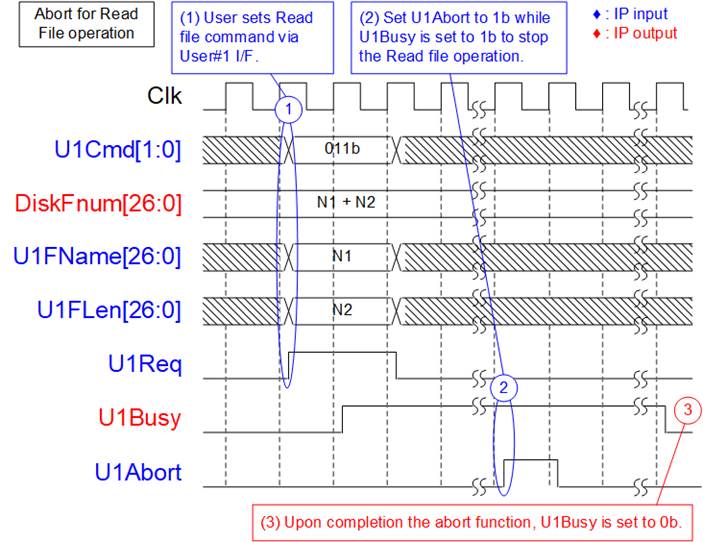
Figure 18: Timing diagram of abort during User#1 Read file command
The operation details of the abort function for Read file operation via User#1 I/F are as follows.
1) The User#1 I/F initiates the Read file command.
2) While executing the Read file operation, indicated by U1Busy being set to 1b, the user sets U1Abort to 1b for a single clock cycle to cancel the operation.
3) Upon completion of the abort function, U1Busy is set to 0b. There is no further data transfer via the User#1 Data interface.
Since the User#0 I/F also supports the Read file command, the user can set U0Abort to 1b to cancel the Read file command, similar to the User#1 I/F, as described in Figure 18.
Verification Methods
The exFAT2 IP Core functionality was verified by simulation and also proved on real board design by using VCK190 and KCU116 boards.
Recommended Design Experience
Experience design engineers with a knowledge of Vivado Tools should easily integrate this IP into their design.
Ordering Information
This product is available directly from Design Gateway Co., Ltd. Please contact Design Gateway Co., Ltd. for pricing and additional information about this product using the contact information on the front page of this datasheet.
Revision History
|
Revision |
Date |
Description |
|
1.00 |
3-May-24 |
Initial Release |