exFAT IP Core for NVMe Data Sheet

Core Facts |
|
|
Provided with Core |
|
|
Documentation |
Reference Design Manual Demo Instruction Manual |
|
Design File Formats |
Encrypted HDL |
|
Instantiation Templates |
VHDL |
|
Reference Designs & Application Notes |
QuartusII Project, See Reference Design Manual |
|
Additional Items |
Demo on Arria10 GX Development Kit |
|
Support |
|
|
Support Provided by Design Gateway Co., Ltd. |
|
Design Gateway Co.,Ltd
E-mail: ip-sales@design-gateway.com
URL: www.design-gateway.com
Features
· Access NVMe device as exFAT system without using CPU and external memory
· Simple user interface and operating with DG NVMe IP
· Achieve the best write/read speed, similar to raw data format by using DG NVMe IP
· Support device capacity: 8 Gigabyte* – 64 Petabyte*
*Gigabyte means 1024x1024x1024 byte while Petabyte means 1024x1024x1024x1024x1024 byte
· Support only 512-byte LBA unit
· Four user commands - Format, Write file, Read file and Shutdown
· Support eight file sizes* - 32MB, 128MB, 512MB, 2GB, 8GB, 32GB, 128GB, and 512GB
*Some file sizes are not available for some device capacities, as shown in Table 2
· Reference design available on Arria10 GX development board with AB18-PCIeX16 and AB16-PCIeXOVR adapter board
Table 1: Example Implementation Statistics
|
Family |
Example Device |
Fmax (MHz) |
Logic utilization (ALMs) |
Registers1 |
Pin |
Block Memory bit |
Design Tools |
|
Arria10 GX |
10AX115S2F45I1SG |
300 |
1,833 |
3,060 |
- |
131,072 |
QuartusII 18.0 |
Notes:
1) Actual logic resource dependent on percentage of unrelated logic
Applications
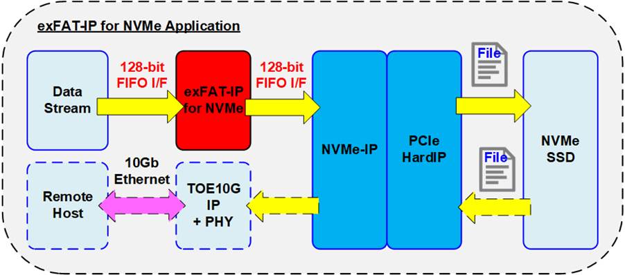
Figure 1: exFAT IP for NVMe Application
exFAT IP for NVMe must integrated with DG NVMe IP and Avalon-ST Hard IP for PCIe (PCIe Hard IP in Intel FPGA device). The IP core is an ideal to access NVMe device as exFAT file system with ultra speed performance, similar to raw data access. This solution fits the application which needs to record data to NVMe device by FPGA, but the data file is read by other hosts such as PC through file system format. As shown in Figure 1, data streaming is recorded to NVMe SSD by using exFAT IP system. The read data path is connected to TOE10G IP, so the remote host can read recorded file via 10Gb Ethernet. The full system is implemented without using external memory such as DDR.
General Description
Typically, file system is implemented by using the software run on CPU for writing or reading data as a file. So, the system must include CPU and memory for storing CPU firmware. Write performance and Read performance when accesssing the device as file system by using CPU firmware are not good. There is much overhead time for CPU managing file system which is effect to reduce the performance. Finally, when high performance under file system is necessary, most designers must design specific file system, not standard file system.
To achieve the above streategy, exFAT IP for NVMe is implemented as CPUless system for writing or reading data in exFAT file system format at very high speed, like raw data access. exFAT IP for NVMe is top-up module of NVMe IP for accessing as file system instead of raw data which is default mode of NVMe IP. The user interface of exFAT IP for NVMe is mostly similar to NVMe IP for easy usage, consisting of control interface and data interface.
Comparing with physical parameters on NVMe IP, exFAT IP uses file parameters instead. File name is used to specify starting point to access data, instead of physical address. The number of written/read files is used to specify transfer size, instead of physical length. Four commands are designed in exFAT IP to access NVMe device - Format, Write file, Read file and Shutdown.
Similar to NVMe IP, data interface of exFAT IP is designed by using general FIFO interface. Also, exFAT IP must use the same clock as user clock of NVMe IP because there is no asynchronous circuit inside exFAT IP to interface with user logic and NVMe IP.
The additional parameters of exFAT IP are created date, created time and file size. Created date and created time must be set when running Format or Write File command for using as created date and time of empty directory or file respectively. File size must be set when running Format operation which can support up to eight size depending on device capacity - 32 MB, 128 MB, 512 MB, 2 GB, 8 GB, 32 GB, 128 GB and 512 GB. More details of supported file size are shown in Table 2.
Table 2: Supported file size following device capacity
|
Device capacity |
32MB(2) |
128MB(2) |
512MB(2) |
2GB(2) |
8GB(2) |
32GB(2) |
128GB(2) |
512GB(2) |
|
8 GB - 16 GB(1) |
Yes |
Yes |
Yes |
Yes |
No |
No |
No |
No |
|
16 GB – 64 GB(1) |
Yes |
Yes |
Yes |
Yes |
Yes |
No |
No |
No |
|
64 GB – 256 GB(1) |
Yes |
Yes |
Yes |
Yes |
Yes |
Yes |
No |
No |
|
256 GB – 1 TB(1) |
Yes |
Yes |
Yes |
Yes |
Yes |
Yes |
Yes |
No |
|
1 TB – 512 TB(1) |
Yes |
Yes |
Yes |
Yes |
Yes |
Yes |
Yes |
Yes |
|
512 TB – 8 PB(1) |
No |
Yes |
Yes |
Yes |
Yes |
Yes |
Yes |
Yes |
|
8 PB – 64 PB(1) |
No |
No |
Yes |
Yes |
Yes |
Yes |
Yes |
Yes |
Note
(1) The upper limit of device capacity must be less than this value. For example, when device capacity is 512 TB, user checks supported file size from row 512 TB – 8 PB, not 1TB – 512 TB.
(2) MB means 1024x1024 byte. GB means 1024x1024x1024 byte.
TB means 1024x1024x1024x1024 byte. PB means 1024x1024x1024x1024x1024 byte.
After finishing Format command, file size cannot be changed. It needs to rerun Format command when the user wants to set the new file size. As a result, after running Format command, 512 empty directories are created in the device, i.e, DIR000, DIR001, …, DIR0FF, DIR100, … , DIR1FE and DIR1FF. Directory name uses three hexadecimal digits to refer directory number. For example, DIR0FF is Directory number 255.
Though 512 directories are created by Format command, some directories are not used for storing the recorded file when the disk capacity is not maximum size. More details are shown in used directory of Table 3.
When running Write file command, the new file is created in the directory. Filename is fixed to seven hexadecimal digits, beginning from 0000000.BIN which is stored in DIR000. The next files (0000001.BIN, 0000002.BIN, … ) are stored to the same directory (DIR000) until total number of file in current directory is arrived to maximum number of file per directory (DirCap signal). After that, the next file is stored to the next directory number (DIR001). Maximum number of file per directory depends on device capacity, as shown in Table 3.
Table 3: Maximum number of file per directory
|
Device capacity |
DirCap[19:0] |
Used directory |
|
8 GB - 32 GB(1) |
0x00100 (256) |
DIR000 - DID003 |
|
32 GB – 128 GB(1) |
0x00200 (512) |
DIR000 - DIR007 |
|
128 GB – 512 GB(1) |
0x00400 (1024) |
DIR000 – DIR00F |
|
512 GB – 2 TB(1) |
0x00800 (2048) |
DIR000 – DIR01F |
|
2 TB – 8 TB(1) |
0x01000 (4096) |
DIR000 – DIR03F |
|
8 TB – 32 TB(1) |
0x02000 (8192) |
DIR000 – DIR07F |
|
32 TB – 128 TB(1) |
0x04000 (16384) |
DIR000 – DIR0FF |
|
128 TB – 512 TB(1) |
0x08000 (32768) |
DIR000 – DIR1FF |
|
512 TB – 2 PB(1) |
0x10000 (65536) |
DIR000 – DIR0FF |
|
2 PB – 8 PB(1) |
0x20000 (131072) |
DIR000 – DIR1FF |
|
8 PB – 32 PB(1) |
0x40000 (262144) |
DIR000 – DIR0FF |
|
32 PB – 64 PB(1)
|
0x80000 (524288) |
DIR000 – DIR0FF |
Functional Description
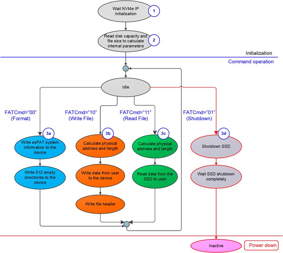
Figure 2: exFAT IP for NVMe Operation
The sequence of exFAT IP Core for NVMe operation is as follows:
1) exFAT IP waits NVMe IP to complete NVMe device initialization.
2) exFAT IP sends Identify command to NVMe IP to get device information such as device capacity. After that, file information of the device are updated such as current file size (DiskFSize) and the number of available files (DiskFnum). After finishing Identify command, exFAT IP is ready to receive new command from user, i.e., Format, Write file, Read file and Shutdown.
Note: File information of the device may be incorrect if the device is not formatted by exFAT IP.
3) The details for each command are described as follows.
a) For the new device which is not formatted by exFAT IP, Format command must be run firstly to clean up the device, set up file system and create 512 empty directories. Besides, Format command is necessary to change file size in the device. After finishing Format command, the number of available files which are output from exFAT IP is reset to 0 (the device does not have the file).
b) When user selects Write file command, the first file name (UserFName) and the number of written files (UserFLen) are received from user. File name and the number of written files are converted to be physical address and total length for setting to NVMe IP and then asserts the Write command request to NVMe IP. Next, data from user is forwarded to NVMe IP until total data are completely transferred. Finally, exFAT IP writes file header to link the user data to each file name.
Note:
- File header is filled to the device as the final step. If system is powered down during writing file command, the file will be lost or corrupt.
- exFAT IP does not validate input value, so User logic must not send out-of-range input to exFAT IP.
c) Similar to Write file command, the first process of Read file command is to calculate start physical address and total length from user inputs (the first file name and the number of read files) for setting to NVMe IP. After that, exFAT IP asserts the Read command request to NVMe IP. Finally, data is returned from NVMe IP to user until total data are completely transferred.
d. The last command which user must be sent before shutdown system is Shutdown command. This command is used to shutdown device in a good sequence. Without Shutdown command, Write data in device cannot be guaranteed. Some data may be remained in the cache within the device and do not flush to flash memory. As a result, the write data may be lost if the system is power down without Shutdown command. After running Shutdown command, NVMe IP and device change to the Inactive state.
exFAT IP for NVMe
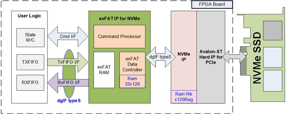
Figure 3: exFAT IP for NVMe Block Diagram
As shown in Figure 3, there are three submodules inside the IP, i.e., Command processor, Data Controller and exFAT RAM. Command processor handles the control interface while Data controller handles the data interface of user logic and NVMe IP. exFAT RAM stores the internal file parameters transferring between Command processor and Data controller. More details of each submodule are described as follows.
l Command processor
This module must control the flow of each command, as shown in Figure 2. The signals of other modules are also controlled and monitored by Command processor. Besides, there are many calculation units for converting file parameters from user to be physical parameters for NVMe IP included in this module. Most file parameters depend on file size and device capacity.
l exFAT RAM
This RAM is implemented by embedded block memory (M9K/M10K/M20K depending on FPGA model) to store file system data. RAM size is 1024x128 bit.
l Data controller
exFAT IP stores three data types in NVMe SSD, i.e., raw data, file system data and file parameters. Raw data is the data in the file which is transferred through FIFO interface of user logic. File system data is constant value which is stored in exFAT RAM. File parameters are the internal parameters which must be calculated from the user inputs and some internal parameters.
l Ram32x128
This module is created by IP catalog inside Quartus tools. The buffer is two-port RAMs (one write port and one read port). RAM depth is 32 words and data size is 128 bit. “Output Registers” are not included, but “Input Registers” are included for “All write input ports” and “rdaddress port”. So, read data latency is equal to one clock cycle. To optimize resource, RAM Block Type is selected to be MLAB.
DG NVMe IP
exFATIP for NVMe is the top-up module of DG NVMe IP. The details of NVMe IP are described in datasheet which can be downloaded from following link.
https://dgway.com/products/IP/NVMe-IP/Altera/dg_nvme_ip_datasheet_altera5_en.pdf
NVMe IP includes 256 KB buffer which is created by IP catalog inside Quartus tools, Ram16kx128Reg. It is two-port RAM (one write port and one read port) which has 16k word depth. Data bus size is 128 bit. RAM is implemented by Block memory with byte enable option. “Input Registers” and “Output Registers” are included for all ports.
User Logic
This module could be designed by using small state machine to send command with other parameters for exFAT IP. Two FIFOs are used to be file data buffer when running Write file and Read file command. However, exFAT IP reference design includes CPU to use JTAG UART as user interface for setting the input parameters and displaying test result and status.
Core I/O Signals
Description of all I/O signals of exFAT IP is provided in Table 4.
Table 4: Core I/O Signals
|
Signal |
Dir |
Description |
|
Clock and Reset |
||
|
RstB |
In |
Synchronous reset signal on Clk domain. Active low. Deassert to ‘1’ after Clk signal is stable. |
|
Clk |
In |
User clock which must be the same clock as Clk input of NVMe IP. The frequency must be more than or equal to PCIeClk which is output from PCIe hard IP. PCIeClk is equal to 125 MHz for PCIe Gen2 and 250 MHz for PCIe Gen3. |
|
User Interface (Command) |
||
|
FSize[2:0] |
In |
File size: “000”: 32MB, “001”: 128MB, “010”: 512MB, “011”: 2GB, “100”: 8GB, “101”: 32GB, “110”: 128GB, “111”: 512GB This input is used in Fomat command only. Note: 1 MB is 1024x1024 byte and 1 GB is 1024x1024x1024 byte |
|
FDateY[6:0] |
In |
Year in created date, count from 1980 (For example, FDateY=39 is year 2019). Please see note in FTimeS description. |
|
FDateM[3:0] |
In |
Month in created date. Valid from 1-12 (1=Jan, 2= Feb, …). Please see note in FTimeS description. |
|
FDateD[4:0] |
In |
Day in created date. Valid from 1-31. Please see note in FTimeS description. |
|
FTimeH[4:0] |
In |
Hour in created time. Valid from 0-23. Please see note in FTimeS description. |
|
FTimeM[5:0] |
In |
Minute in created time. Valid from 0-59. Please see note in FTimeS description. |
|
FTimeS[4:0] |
In |
x2 sec in created time. Valid from 0-29 (1=2, 2=4, …). Note: FDateY, FDateM, FDateD, FTimeH, FTimeM and FTimeS are applied to be created time of directory in Format command and created time of file in Write file command. |
|
UserCmd[1:0] |
In |
User Command. “00”: Format command, “01” Shut down, “10”: Write file, ”11”: Read file. |
|
UserFName[26:0] |
In |
The first file name to write/read file (0=”0000000.BIN”, 1=”0000001.BIN”, …). Valid from 0 to TotalFCap - 1. This input is used in Write file and Read file command. When running Write file command, this value must be less than or equal to DiskFnum signal. It is recommended to set this value equal to DiskFnum in Write file command. Therefore, the first file name of the new write command is the next value from the last file in the device. |
|
UserFLen[26:0] |
In |
Total files transferring in the request. Valid from 1 to (TotalFCap – UserFName). This input is used in Write file and Read file command. |
|
UserReq |
In |
Assert to ‘1’ to send the new command request with the valid value on FSize, UserCmd, UserFName, UserFLen, FDateYMD and FTimeHMS. Each command needs different input parameters. This signal could be asserted to ‘1’ when the IP is Idle only (UserBusy=’0’). |
|
UserBusy |
Out |
Assert to ‘1’ when IP is busy. |
|
TotalFCap[26:0] |
Out |
Maximum number of files to store in NVMe device. This value is valid after exFAT IP completes initialization process (UserBusy=’0’). Please see note in DiskFnum description. |
|
DirCap[19:0] |
Out |
Maximum number of files to store in one directory. This value is valid after exFAT IP completes initialization process (UserBusy=’0’). |
|
DiskFsize[2:0] |
Out |
Current file size used in NVMe device. This signal is valid after exFAT IP completes initialization process (UserBusy=’0’). Please see note in DiskFnum description. |
|
Signal |
Dir |
Description |
|
User Interface (Command) |
||
|
DiskFnum[26:0] |
Out |
The number of available files stored in the device. This signal is valid after exFAT IP completes the initialization process or Write command process (UserBusy=’0’). Note: TotalFCap, DiskFsize and DiskFnum will not be correct if NVMe device has never been formatted by exFAT IP.. |
|
UserError |
Out |
Error flag. Asserted to ‘1’ when UserErrorType is not equal to 0. The flag is cleared to ‘0’ by asserting RstB signal to NVMe IP and exFAT IP. |
|
UserErrorType[31:0] |
Out |
[23:0] - Direct mapped to NVMeErrorType signal of NVMe IP. Please see more details in NVMe IP datasheet. [24] - Error when device capacity is out of range (more than or equal to 64 PetaByte or less than 8 GigaByte) [25] – Error when LBA unit of NVMe SSD is not equal to 512 byte. |
|
IPVesion[31:0] |
Out |
IP version number |
|
TestPin[63:0] |
Out |
Reserved to be IP test point. |
|
User Interface (Data) |
||
|
UserFifoWrCnt[15:0] |
In |
Write data counter of Rx FIFO. Used to check full status. If total FIFO size is less than 16-bit, please fill ‘1’ to upper bit. UserFifoWrEn can be asserted to ‘1’ when UserFifoWrCnt[15:6] is not equal to all 1. |
|
UserFifoWrEn |
Out |
Asserted to ‘1’ to write data to Rx FIFO when receiving data from NVMe SSD through NVMe IP during running Read file command. |
|
UserFifoWrData[127:0] |
Out |
Write data bus of Rx FIFO. Valid when UserFifoWrEn=’1’. |
|
UserFifoRdCnt[15:0] |
In |
Read data counter of Tx FIFO. Used to check total number of data stored in FIFO. If FIFO size signal is less than 16-bit, please fill ‘0’ to upper bit. |
|
UserFifoEmpty |
In |
This signal is unused for this IP. |
|
UserFifoRdEn |
Out |
Asserted to ‘1’ to read data from Tx FIFO and send to NVMe SSD through NVMe IP during running Write file command. |
|
UserFifoRdData[127:0] |
In |
Read data returned from Tx FIFO. Valid in the next clock after UserFifoRdEn is asserted to ‘1’. |
|
NVMe IP User Interface (Connect to dgIF typeS of NVMe IP) (Please see more details from NVMe IP datasheet) |
||
|
NVMeCmd[2:0] |
Out |
Connect to UserCmd of NVMe IP |
|
NVMeAddr[47:0] |
Out |
Connect to UserAddr of NVMe IP |
|
NVMeLen[47:0] |
Out |
Connect to UserLen of NVMe IP |
|
NVMeReq |
Out |
Connect to UserReq of NVMe IP |
|
NVMeBusy |
In |
Connect to UserBusy of NVMe IP |
|
NVMeLBASize[47:0] |
In |
Connect to LBASize of NVMe IP |
|
NVMeLBAMode |
In |
Connect to LBAMode of NVMe IP |
|
NVMeCtmSubmDW0[31:0] - NVMeCtmSubmDW15[31:0] |
Out |
Connect to CtmSubmDW0 – CtmSubmDW15 of NVMe IP |
|
NVMeError |
In |
Connect to UserError of NVMe IP |
|
NVMeErrorType[31:0] |
In |
Connect to UserErrorType of NVMe IP |
|
Signal |
Dir |
Description |
|
NVMe IP User Interface (Connect to dgIF typeS of NVMe IP) (Please see more details from NVMe IP datasheet) |
||
|
NVMeFifoWrCnt[15:0] |
Out |
Connect to UserFifoWrCnt of NVMe IP |
|
NVMeFifoWrEn |
In |
Connect to UserFifoWrEn of NVMe IP |
|
NVMeFifoWrData[127:0] |
In |
Connect to UserFifoWrData of NVMe IP |
|
NVMeFifoRdCnt[15:0] |
Out |
Connect to UserFifoRdCnt of NVMe IP |
|
NVMeFifoEmpty |
Out |
Connect to UserFifoEmpty of NVMe IP |
|
NVMeFifoRdEn |
In |
Connect to UserFifoRdEn of NVMe IP |
|
NVMeFifoRdData[127:0] |
Out |
Connect to UserFifoRdData of NVMe IP |
Timing Diagram
Initialization
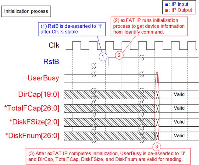
Figure 4: exFAT IP for NVMe Intialization
The steps of the initialization process are as follows.
1) RstB is released to ‘1’ by user after Clk is stable.
2) exFAT IP begins initialization process by sending Identify command to NVMe IP. After that, device information returned from Identify command is processed by exFAT IP to calculate file system information.
3) UserBusy is deasserted to ‘0’ after exFAT IP finishes processing Identify data from NVMe IP. Next, four output signals from exFAT IP to show device information are valid to read, i.e., DirCap (maximum number of file per directory), TotalFCap (maximum number of file stored in device), DiskFsize (file size in device) and DiskFnum (available file stored in device).
After finishing the above sequence, exFAT IP is ready to receive the new command from user. User can send four commands for exFAT IP opreating with assigning the input signals. The inputs for each command are different. Please see more details in the next topic.
*Note: DirCap is always reliable after completing initialization sequence, but TotalFCap, DiskFsize and DiskFnum are valid when the device has been formatted by exFAT IP. Otherwise, TotalFCap, DiskFsize and DiskFnum are incorrect.
Format command
Format command is necessary if some of following conditions are met.
1) The device has never been formatted by exFAT IP.
2) User needs to delete all files in the device.
3) User needs to change file size in the device.
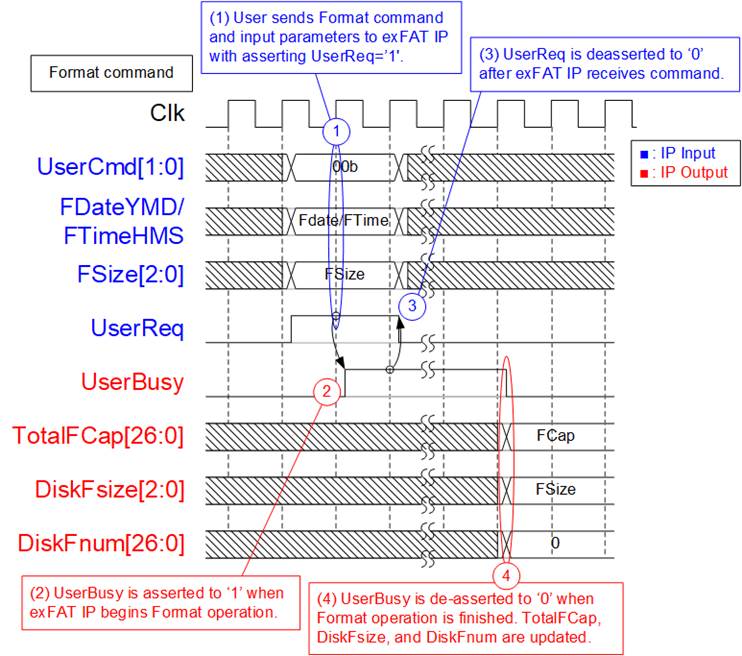
Figure 5: Timing diagram of Format command
The example steps of control interface to run Format command are as follows.
1) User sets UserCmd = 00b (Format), FDate (created date), FTime (created time) and FSize (file size to write in Write file command) with asserting UserReq to ‘1’.
2) exFAT IP asserts UserBusy to ‘1’ and starts Format command operation following the input parameters.
3) UserReq is de-asserted to ‘0’ to complete the current request. Then, user logic waits until Format operation is finished by monitoring UserBusy.
4) UserBusy is de-asserted to ‘0’ after finishing creating file system information and 512 empty directories (DIR000 – DIR1FF) in the device. TotalFCap (maximum number of files in the device), DiskFsize (file size setting in the device) and DiskFnum (total available files in the device) are updated. DiskFsize is equal to Fsize input during Format command request while DiskFnum is reset to 0 (device is empty). Created date and created time of empty directory are equal to FDataYMD and FTimeHMS input.
Shutdown command
Shutdown command is recommended to send as the last command before power down the system. When Shutdown command is issued, SSD flushes the data from the internal cache to flash memory. After finishing this command, NVMe IP and SSD are not available and user needs to power off/on the system to rerun NVMe IP and SSD.
For safety shutdown, it is recommended to send Shutdown command to the SSD. When the SSD is powered down without Shutdown command, the total count of unsafe shutdowns will be increased.
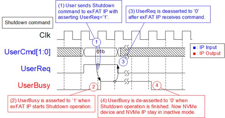
Figure 6: Timing diagram of Shutdown command
The example steps of command interface to run Shutdown command are as follows.
1) Set UserCmd = 01b (Shutdown) with asserting UserReq to ‘1’.
2) exFAT IP asserts UserBusy to ‘1’ and starts Shutdown command operation.
3) UserReq is de-asserted to ‘0’ to complete the current request. Then, user logic waits until Shutdown operation is finished by monitoring UserBusy.
4) UserBusy is de-asserted to ‘0’ after finishing Shutdown command. The system can be powered down without data lost problem.
Write File command
To operate Write file command, user sets the input parameters of Write file command to control interface of exFAT IP and then data is read from user logic by exFAT IP via data interface.
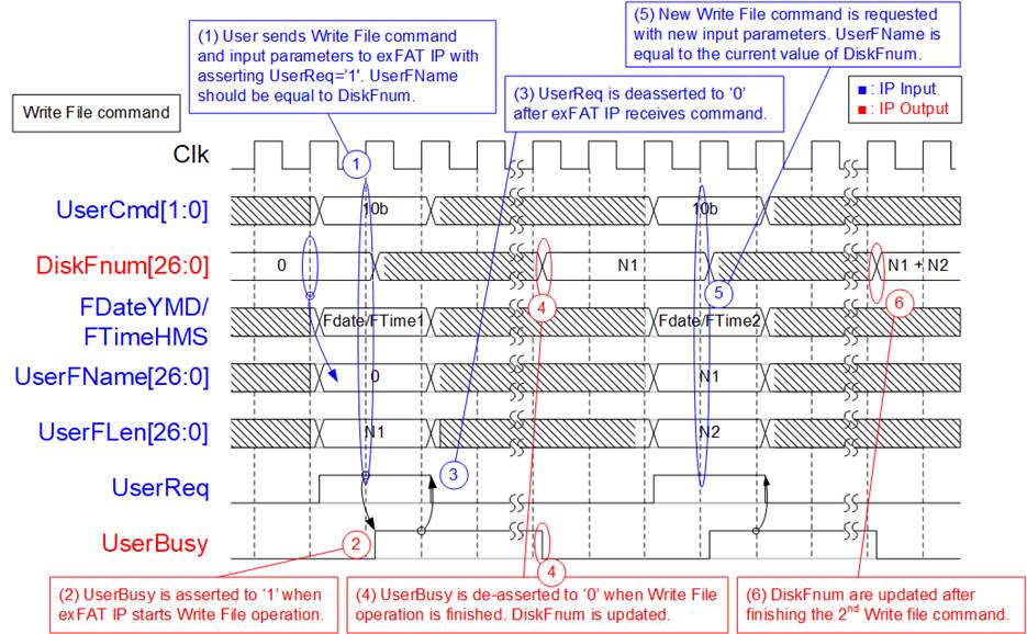
Figure 7: Timing diagram of control interface during Write file command
The example steps of control interface to run Write file command are as follows.
1) User sets UserCmd = 10b (Write File), FDate (created date), FTime (created time), UserFName (the first file name to write), and UserFLen (total number of written file) with asserting UserReq to ‘1’. UserFName should be equal to DiskFnum to create new file name which is the next value from the latest name. UserFLen must not be more than TotalFCap - UserFName. As shown in Figure 7, UserFName is equal to 0 when running the first Write file command to empty device.
Note: If the new file name is more than DiskFnum, it is maloperation and the new file is not found in the device.
2) exFAT IP asserts UserBusy to ‘1’ and starts Write file command operation by using the input parameters.
3) UserReq is de-asserted to ‘0’ to complete the current request. Then, user logic waits until Write file operation is finished by monitoring UserBusy. In Write file operation, the data interface of exFAT IP forwards data from user logic to store in NVMe SSD via NVMe IP.
4) UserBusy is de-asserted to ‘0’ after finishing forwarding total data. DiskFnum is updated to be equal to UserFName + UserFLen. Created date and created time of the new file are equal to FDataYMD and FTimeHMS input.
5) UserFName of the next Write file command should be equal to DiskFnum which has been updated from the previous Write file command. FDate and FTime of the new Write file command can be changed.
6) DiskFnum is increased to show total available file in the device after finishing Write file command. In the example, the last value of DiskFnum is equal to N1 (UserFLen of the 1st Write file command) + N2 (UserFLen of the 2nd Write file command).
Assumed that N1+N2 is less than DirCap (one directory can store all new files in the 1st and 2nd Write file command), the new file in the device is created within the same directory, as shown in Figure 8. The 1st file name is 0000000.BIN and the last file name is (N1 + N2).BIN. Total digit of file name is fixed to 7, so 0 digit is filled as a prefix of filename in the device.
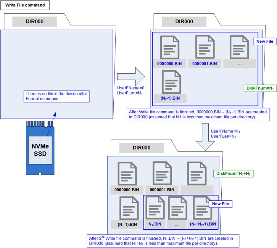
Figure 8: New file is created in the device after finishing Write file command
After exFAT IP receives Write file command request from user, the next process is transferring data from user logic to NVMe IP.
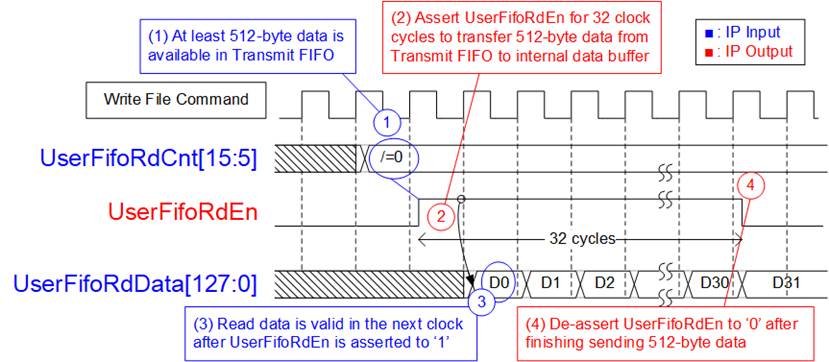
Figure 9: TX FIFO Interface for Write file command
Figure 9 shows timing diagram of data interface during Write file command operation.
1) Before running a new burst write, UserFifoRdCnt[15:5] is monitored. The IP waits until at least 512-byte data is available in Transmit FIFO (UserFifoRdCnt[15:5] is not equal to 0).
2) Assert UserFifoRdEn to ‘1’ for 32 clock cycles to read 512-byte data from Transmit FIFO.
3) UserFifoRdData is valid in the next clock after asserting UserFifoRdEn to ‘1’. 32 data are read continuously.
4) UserFifoRdEn is deasserted to ‘0’ after reading the 32th data. If total data is not transferred, the IP goes back to step 1) for transferring the next 512-byte data. Otherwise, the IP changes to the Idle state.
Total data size for one command depends on UserFLen and File size. When UserFLen = N1, total number of 128-bit data is equal to N1 x (File size in byte unit / 16).
Read File command
To operate Read file command, user sets the input parameters of Read file command to the control interface of exFAT IP. The inputs for Read File command are UserFName and UserFLen. After that, data is sent by exFAT IP to user logic via the data interface.
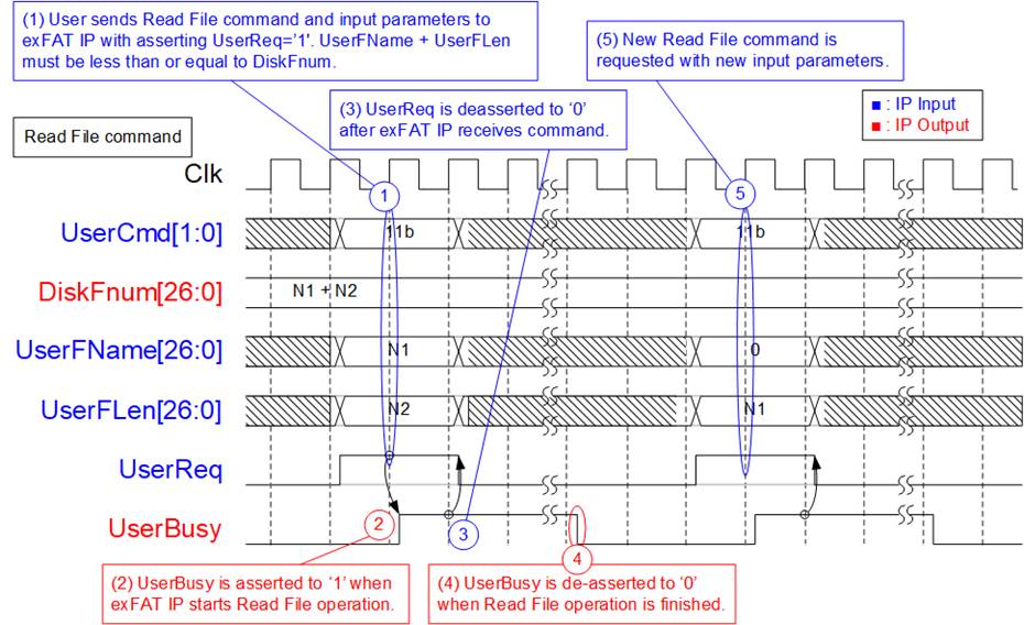
Figure 10: Timing diagram of control interface during Read file command
The example steps of control interface to run Read file command are as follows.
1) User sets UserCmd = 11b (Read File), UserFName (the first file name to read) and UserFLen (total number of read file) with asserting UserReq to ‘1’. The caution point is UserFName + UserFLen must be less than or equal to DiskFnum (total available file in the device).
2) exFAT IP asserts UserBusy to ‘1’ and starts Read file command operation by using the input parameters.
3) UserReq is de-asserted to ‘0’ to complete the current request. Then, user logic waits until Read file operation is finished by monitoring UserBusy. In this step, the data interface of exFAT IP forwards read data in NVMe SSD from NVMe IP to user logic.
4) UserBusy is de-asserted to ‘0’ after finishing forwarding total data. DiskFnum is stable during Read file operation.
5) User can send the new command request to exFAT IP.
Data interface to transfer data from the device to user logic is displayed on Figure 11.
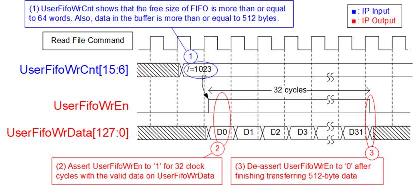
Figure 11: RX FIFO Interface for Read file command
For Read file command, UserFifoWrEn is asserted to ‘1’ with the valid value of UserFifoWrData to send data to the user via FIFO interface.
1) Before starting a new burst transfer, UserFifoWrCnt[15:6] is monitored. The IP waits until the free space of Received FIFO is much enough (UserFifoWrCnt[15:6] is not equal to all 1 or 1023).
2) Assert UserFifoWrEn to ‘1’ for 32 clock cycles to transfer 512-byte data from NVMe IP to user.
3) After transferring 512-byte data, UserFifoWrEn is de-asserted to ‘0’. If total data is not transferred, the IP goes back to step 1) to check FIFO status and the number of received data from SSD for transferring the next 512-byte data.
Similar to Write file command, total size of 128-bit data is equal to UserFLen x (File size in byte unit / 16).
Error
UserError is asserted to ‘1’ by error condition within NVMe IP or exFAT IP. The details of error status are monitored by UserErrorType. To clear Error flag, user needs to assert reset signal (RstB=’0’) to exFAT IP and NVMe IP.
Figure 12: Error flag timing diagram
Limitation
(1) NVMe device which is connected to exFAT IP must be formatted by exFAT IP. The maloperation will be happened such as wrong device information (TotalFCap, DiskFsize and DiskFnum) if the device is not formatted by exFAT IP.
(2) All files in NVMe device must be written by exFAT IP. The maloperation will be happened in the system if the device includes some files which is written by the other hosts.
(3) The other hosts can access NVMe device as read-only mode.
(4) All files in NVMe device have the same size which is defined by FSize during Format command. To change FSize value, the device must be formatted again with new FSize value.
(5) Table 3 shows the maximum number of files to store in one directory which depends on device capacity. The equation to calculate directory name which stores the file from filename is as follows.
DIR Name = (<FileName>/DirCap) – 1
Assumed that device capacity is 100 GB, DirCap (the maximum number of file in one directory) is equal to 512.
0000000.BIN – 000001FF.BIN are stored to DIR000.
0000200.BIN – 000003FF.BIN are stored to DIR001.
0000400.BIN – 000005FF.BIN are stored to DIR002.
0000600.BIN – 000007FF.BIN are stored to DIR003.
0000800.BIN – 000009FF.BIN are stored to DIR004.
0000A00.BIN – 00000BFF.BIN are stored to DIR005.
0000C00.BIN – 00000DFF.BIN are stored to DIR006.
0000E00.BIN – 00000FFF.BIN are stored to DIR007.
DIR008 – DIR1FF are empty directories.
(6) In Write file command, UserFName input should be equal to DiskFnum.
a) If UserFName is more than DiskFnum, it is the error condition. After running by this condition, the new file is not found in the device and DiskFnum value is not correct.
b) If UserFName is less than DiskFnum, the old file is replaced by the new data. DiskFnum does not change if the sum of UserFName and UserFlen in the new write request is less than the current value of DiskFnum. DiskFnum to show total number of file in the device is not reduced without running Format command.
Verification Methods
The exFAT IP Core for NVMe functionality was verified by simulation and also proved on real board design by using Arria10 GX development board.
Recommended Design Experience
Experience design engineers with a knowledge of Quartus tools should easily integrate this IP into their design.
Ordering Information
This product is available directly from Design Gateway Co., Ltd. Please contact Design Gatway Co., Ltd. for pricing and additional information about this product using the contact information on the front page of this datasheet.
Revision History
|
Revision |
Date |
Description |
|
1.0 |
22-Jan-2019 |
New release |
|
1.1 |
22-Mar-2019 |
Add DiskFsize and DiskFnum input |
|
1.2 |
10-May-2019 |
Update the maximum number of file per directory |
|
1.3 |
15-Dec-2020 |
Update company info and timing diagram |