FAT32 IP Core for NVMe Data Sheet

Core Facts |
|
|
Provided with Core |
|
|
Documentation |
Reference Design Manual Demo Instruction Manual |
|
Design File Formats |
Encrypted File |
|
Instantiation Templates |
VHDL |
|
Reference Designs & Application Notes |
Vivado Project, See Reference Design Manual |
|
Additional Items |
Demo on ZC706, KCU105, ZCU106 |
|
Support |
|
|
Support Provided by Design Gateway Co., Ltd. |
|
Design Gateway Co.,Ltd
E-mail: ip-sales@design-gateway.com
URL: design-gateway.com
Features
· Operating with DG NVMe IP Core to access NVMe SSD using FAT32 file system without CPU usage or external memory
· Simple user interface with four supported commands: Format, Write file, Read file, and Shutdown.
· Supported SSD capacity: 64 MB – 2 TB with 512-byte LBA unit
· Supported seven file sizes: 32MB, 64MB, 128MB, 256MB, 512MB, 1024MB, 2048MB
· Maximum write speed up to 2300 MB/s and read speed up to 3300 MB/s
· Reference design available on ZC706/KCU105/ZCU106 board with AB17-M2FMC, AB18-PCIeX16, or AB19-M2PCI adapter board
Table 1: Example Implementation Statistics for Ultrascale/Ultrascale+ device
|
Family |
Example Device |
Fmax (MHz) |
CLB Regs |
CLB LUTs |
CLB |
IOB |
BRAMTile1 |
PLL |
GTX |
Design Tools |
|
Kintex-Ultrascale |
XCKU040FFVA1156-2E |
350 |
1338 |
1337 |
270 |
- |
2.5 |
- |
- |
Vivado2019.1 |
|
Zynq-Ultrascale+ |
XCZU7EVFFVC1156-2E |
400 |
1338 |
1344 |
279 |
- |
2.5 |
- |
- |
Vivado2019.1 |
Table 2: Example Implementation Statistics for 7-Series device
|
Family |
Example Device |
Fmax (MHz) |
Slice Regs |
Slice LUTs |
Slices |
IOB |
BRAMTile1 |
PLL |
GTX |
Design Tools |
|
Zynq-7000 |
XC7Z045FFG900-2 |
300 |
1338 |
1327 |
449 |
- |
2.5 |
- |
- |
Vivado2019.1 |
Notes: 1) Actual logic resource dependent on percentage of unrelated logic
Applications
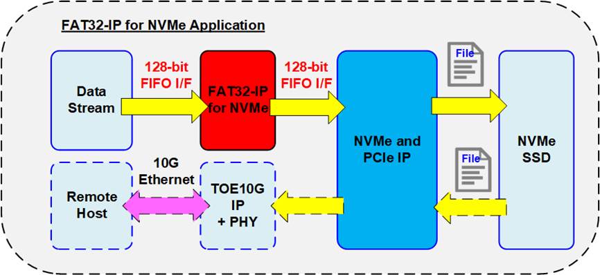
Figure 1: FAT32 IP for NVMe Application
FAT32 IP for NVMe requires the integration with DG NVMe IP and low-layer hardware for PCIe interface. This IP core provides an efficient solution to access an NVMe device using the FAT32 file system with achieving high-speed performance comparable to raw data access. This solution is suitable for applications that require FPGA-based data recording to NVMe device, while allowing other hosts such as the computer o read the data files in the file system format.
As shown in Figure 1, data stream is recorded to an NVMe SSD via FAT32 IP system. The read data interface is connected to the TOE10G IP, enabling the remote host to access the recorded file via 10G Ethernet connection. This system is implemented without the need for external memory such as DDR.
General Description
File system is traditionally implemented using software running on the processor for writing or reading data as files. Therefore, the system must include a CPU and memory to execute the software. However, the write and read performance when accessing the device as file system by using CPU software is limited. There is an overhead time for handling file system by CPU, leading to decreased performance. Therefore, when high-performance file system operations are required, a customized file system is applied instead of standard file system.
To overcome this challenge, the FAT32 IP for NVMe has been developed as a CPUless system. This IP enables high-speed writing or reading data in FAT32 file system format, delivering performance comparable to raw data access. The FAT32 IP for NVMe serves as an add-on module to the NVMe IP, enabling access to the NVMe device as file system rather than raw data, which is default mode of the NVMe IP. The user interface of FAT32 IP for NVMe closely resembles that of the NVMe IP, ensuring ease of use. It consists of both control interface and data interface.
While the NVMe IP uses physical parameters, the FAT32 IP uses file parameters instead. The starting position for writing or reading data is determined by the File name, rather than a physical address. The transfer size of written/read data is determined by the number of files, rather than transfer size in 512-byte units. The FAT32 IP supports four commands for accessing the NVMe device: Format, Write file, Read file, and Shutdown.
Similar to the NVMe IP, the data interface of the FAT32 IP is designed using a standard FIFO interface. Additionally, the FAT32 IP must use the same clock as the user clock of the NVMe IP, as there is no asynchronous circuit within FAT32 IP for interfacing with user logic and the NVMe IP.
The FAT32 IP introduces additional parameters including created date, created time, and file size. When executing the Write file command, the created date and time correspond to the data and time of file creation. The file size is applied during the execution of the Format, Write file, and Read file commands. Note that the file size cannot be changed without executing the Format command. The supported file sizes ranges from 32 MB to 2 GB. Additionally, the FAT32 IP supports various SSD capacities, ranging from 64 MB to 2 TB with a single partition.
Functional Description
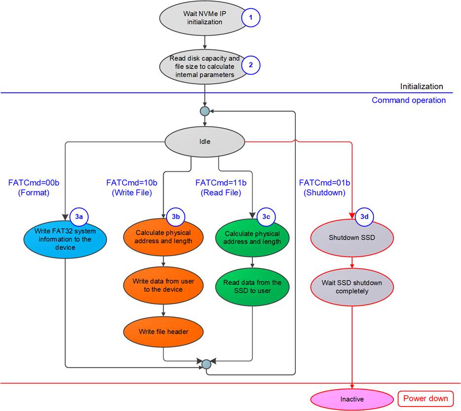
Figure 2: FAT32 IP for NVMe Operation
The sequence of FAT32 IP Core for NVMe operation is as follows:
1) The FAT32 IP waits until the NVMe IP completes NVMe device initialization.
2) Once the NVMe device initialization is finished, the FAT32 IP sends Identify command to NVMe IP to get device information such as the capacity. It also reads the user-defined File size input to prepare the system parameters and calculate the maximum number of files (TotalFCap) that can be stored on the SSD. After the completion of the Identify command, the FAT32 IP is ready to receive new commands from the user, including Format, Write file, Read file, and Shutdown commands.
3) The execution details for each command are described below.
a) Format command: This command is required for new SSD that has not been formatted by the FAT32 IP. It cleans up the SSD and sets up the file system. Once the Format operation is completed, the FAT32 file structure, such as Master boot record and root directory, is written to the SSD. If the user updates the file size input in this command, the TotalFCap value will be also updated accordingly.
b) Write file command: When the user selects the Write file command and provides the first file name (UserFName) and the number of files (UserFLen), the FAT32 IP calculates the corresponding physical address and total transfer size in 512-byte units. It then generates the write request to the NVMe IP. Once all the user’s data is completely transferred to the SSD through the NVMe IP, the FAT32 IP writes the file header to link the user data to each file entry.
Note:
i) The file header is written to the SSD in the final step. If the system is powered down during the execution of the Write file command, all written files may be lost or corrupted.
ii) The FAT32 IP does not validate the input values set by user, so the user logic should ensure that the inputs provided to the FAT32 IP are in the valid range.
c) Read file command: Similar to Write file command, the first step of the Read file command is to determine the physical address and total transfer size based on the user inputs. Afterwards, the FAT32 IP asserts a Read command request to the NVMe IP and forwards the read data from the SSD to the user until the end of transfer.
d) Shutdown command: The Shutdown command must be sent by the user before powering off the system. This command ensures a proper shutdown sequence for the device. Without the Shutdown command, the write data in the device cannot be guaranteed. Some data may remain in the cache within the device and may not be flushed to that flash memory. As a result, the write data may be lost if the system is power down without issuing Shutdown command. After running the Shutdown command, the NVMe-IP and the SSD become inactive status.
FAT32 IP for NVMe

Figure 3: FAT32 IP for NVMe Block Diagram
Figure 3 illustrates three submodules within FAT32 IP, i.e., Command processor, Data Controller, and FAT32 RAM. Command processor handles the control interface while Data controller handles the data interface of both user module and the NVMe IP. FAT32 RAM stores the file system parameters for internal usage inside both Command processor and Data controller. Further details of each submodule are described below.
l Command processor
This submodule handles the generation of command request, data transfer for the required command, and monitoring the status of the command completion. This submodule acts as the core engine, ensuring proper sequencing and coordination of the other submodules. It incorporates various calculation units that determine file system parameters and NVMe IP parameters during the execution of each command. The file system parameters mostly depend on the user inputs such as file size and SSD capacity.
l FAT32 RAM
This submodule RAM is implemented using BlockRAM to store FAT32 file system data. The size is 256x128-bit.
l FAT32 Data Controller
This submodule handles the data transfer between the user and the NVMe IP. Data is simply categorized into three types: raw data, file system data, and file parameters. The raw data represents the actual data contained within each file, directly transferred through TxFIFO and RxFIFO interface at the user interface. The file system data is sourced from the internal parameters stored at FAT32 RAM. Finally, the file parameters are variables calculated based on user inputs and specific internal parameters.
NVMe IP
The FAT32 IP for NVMe serves as an add-on module of the NVMe IP. The NVMe IP implements as the NVMe host controller, enabling direct access to an NVMe SSD through PCIe interface. Integration of the NVMe IP requires the utilization of the Integrated Block for PCIe (PCIe hard IP) from Xilinx. For more information about the NVMe IP, please refer to the datasheet available on our website at the following link.
https://dgway.com/products/IP/NVMe-IP/dg_nvme_ip_data_sheet_en/
User Logic
The user logic module can be designed simply using a state machine to act as a sequencer for sending the command requests along with their parameters. Additionally, two FIFOs can be incorporated for data transfer with the FAT32 IP, one for Write file operation and another for Read file operation. An example user logic implementation is provided in the reference design of the FAT32 IP.
Core I/O Signals
Descriptions of all signal I/O are provided in Table 3.
Table 3: Core I/O Signals
|
Signal |
Dir |
Description |
|
Clock and Reset |
||
|
RstB |
In |
Synchronous reset signal. Active low. De-assert to 1b after the Clk signal is stable. |
|
Clk |
In |
User clock which must be the same clock as Clk input of the NVMe IP. (At least 125 MHz for PCIe Gen2 or 250 MHz for PCIe Gen3). |
|
User Interface (Command) |
||
|
FSize[2:0] |
In |
File size (000b: 32MB, 001b: 64MB, 010b: 128MB, 011b: 256MB, 100b: 512MB, 101b: 1024MB, 110b: 2048MB, 111b: Reserved) Note: 1) 1 MB is 1024x1024 byte 2) FSize cannot be changed while the IP is operating. |
|
FDateY[6:0] |
In |
Year in created date, count from 1980 (For example, FDateY=37 is year 2017). Please see note in FTimeS description. |
|
FDateM[3:0] |
In |
Month in created date. Valid from 1-12 (1=Jan, 2= Feb, …). Please see note in FTimeS description. |
|
FDateD[4:0] |
In |
Day in created date. Valid from 1-31. Please see note in FTimeS description. |
|
FTimeH[4:0] |
In |
Hour in created time. Valid from 0-23. Please see note in FTimeS description. |
|
FTimeM[5:0] |
In |
Minute in created time. Valid from 0-59. Please see note in FTimeS description. |
|
FTimeS[4:0] |
In |
x2 sec in created time. Valid from 0-29 (1=2, 2=4, …). Note: FDateY, FDateM, FDateD, FTimeH, FTimeM and FTimeS are applied to be created time of file in Write file command. These values must not be changed during operation. |
|
UserCmd[1:0] |
In |
User Command. 00b: Format command, 01b: Shutdown, 10b: Write file, 11b: Read file. |
|
UserFName[15:0] |
In |
The first file name to write/read file (0= FILE0000.BIN, 1=FILE0001.BIN, …). Valid form 0 to TotalFCap - 1. This input is used in Write file and Read file commands. Note: For the Write file command, this value should be equal to the next value after the latest written file number stored in the SSD for continuous transfer. |
|
UserFLen[15:0] |
In |
Total files in the command request. Valid from 1 to (TotalFCap – UserFName). This input is used in Write file and Read file commands. |
|
UserReq |
In |
Asserted to 1b when the IP is Idle (UserBusy=0b) to send the new command request. Each command requires different parameters which will be described later in this document. |
|
UserBusy |
Out |
Asserted to 1b when the IP is busy status. New command request will not be allowed if this signal is asserted to 1b. |
|
TotalFCap[15:0] |
Out |
Maximum number of files to store in the SSD. This value is updated after FAT32-IP completes initialization process. |
|
UserError |
Out |
Error flag. Asserted to 1b when UserErrorType is not equal to 0. The flag is cleared to 0b by asserting RstB signal to both the NVMe IP and the FAT32 IP. |
|
UserErrorType[31:0] |
Out |
[31:17] - Direct mapped to NVMeErrorType[31:17] of NVMe IP. [16] - Error from unsupported LBA unit (LBA unit is not equal to 512 bytes). [15:0] - Direct mapped to NVMeErrorType[15:0] of NVMe IP. Note: Further details of NVMeErrorType signal are described in NVMe IP datasheet |
|
IPVesion[31:0] |
Out |
IP version number |
|
TesPin[63:0] |
Out |
Reserved to be IP test point. |
Signal |
Dir |
Description |
|
User Interface (Data) |
||
|
UserFifoWrCnt[15:0] |
In |
Write data counter of Rx FIFO. Used to check full status. If FIFO data count is less than 16 bits, please fill 1b to upper bits. UserFifoWrEn can be asserted to 1b when UserFifoWrCnt[15:3] is not equal to all 1. |
|
UserFifoWrEn |
Out |
Asserted to 1b to write data to Rx FIFO when receiving data from NVMe SSD through NVMe IP during the execution of Read file command. |
|
UserFifoWrData[127:0] |
Out |
Write data bus of Rx FIFO. Valid when UserFifoWrEn=1b. |
|
UserFifoRdCnt[15:0] |
In |
Read data counter of Tx FIFO. Used to check total amount of data stored in FIFO. If FIFO data count is less than 16 bits, please fill 0b to upper bits. |
|
UserFifoEmpty |
In |
This signal is unused for this IP. |
|
UserFifoRdEn |
Out |
Asserted to 1b to read data from Tx FIFO and then forward it to NVMe SSD through NVMe IP during the execution of Write file command. |
|
UserFifoRdData[127:0] |
In |
Read data returned from Transmit FIFO. Valid in the next clock after UserFifoRdEn is asserted to 1b. |
|
NVMe IP User Interface (Connect to dgIF typeS of NVMe IP) (Please see more details from NVMe IP datasheet) |
||
|
NVMeCmd[2:0] |
Out |
Connect to UserCmd of NVMe IP |
|
NVMeAddr[47:0] |
Out |
Connect to UserAddr of NVMe IP |
|
NVMeLen[47:0] |
Out |
Connect to UserLen of NVMe IP |
|
NVMeReq |
Out |
Connect to UserReq of NVMe IP |
|
NVMeBusy |
In |
Connect to UserBusy of NVMe IP |
|
NVMeLBASize[31:0] |
In |
Connect to LBASize[31:0] of NVMe IP. However, if LBASize[47:32] of NVMe IP is not equal to 0, it is recommended to input the maximum possible value, represented by all ones. |
|
NVMeLBAMode |
in |
Connect to LBAMode of NVMe IP |
|
NVMeCtmSubmDW0[31:0] - NVMeCtmSubmDW15[31:0] |
Out |
Connect to CtmSubmDW0 – CtmSubmDW15 of NVMe IP |
|
NVMeError |
In |
Connect to UserError of NVMe IP |
|
NVMeErrorType[31:0] |
In |
Connect to UserErrorType of NVMe IP |
|
NVMeFifoWrCnt[15:0] |
Out |
Connect to UserFifoWrCnt of NVMe IP |
|
NVMeFifoWrEn |
In |
Connect to UserFifoWrEn of NVMe IP |
|
NVMeFifoWrData[127:0] |
In |
Connect to UserFifoWrData of NVMe IP |
|
NVMeFifoRdCnt[15:0] |
Out |
Connect to UserFifoRdCnt of NVMe IP |
|
NVMeFifoEmpty |
Out |
Connect to UserFifoEmpty of NVMe IP. |
|
NVMeFifoRdEn |
In |
Connect to UserFifoRdEn of NVMe IP |
|
NVMeFifoRdData[127:0] |
Out |
Connect to UserFifoRdData of NVMe IP |
Timing Diagram
Initialization
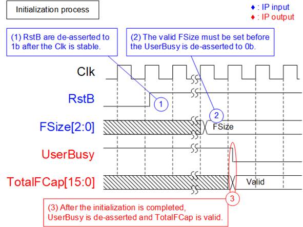
Figure 4: FAT32-IP for NVMe Initialization
The steps of the initialization process are as follows.
1) De-asserts RstB to 1b to begin the FAT32 IP initialization process. It is recommended to use the same reset signal as the reset of the NVMe IP. For more detailed information, please refer to the NVMe IP datasheet.
2) The FAT32 IP then waits until the NVMe IP is ready to send the Identify command request. During the FAT32 IP initialization process, the user should configure the FSize parameter with a valid value. This FSize value is applied to calculate the TotalFCap output signal.
3) Once the NVMe IP completes the Identify command and the SSD information is received by the FAT32 IP, the file system information is calculated. Afterward, the UserBusy is de-asserted to 0b, allowing the user to send command requests. At this time, the maximum number of files (TotalFCap) is also available for reading.
Format command
Format command is necessary under the following conditions.
1) The device has never been formatted by FAT32 IP.
2) The user needs to delete all files on the SSD.
3) The user needs to change file size on the SSD.

Figure 5: Timing diagram of Format command
The steps to execute Format command are described below.
1) Set UserCmd = 00b (Format) along with FSize parameter while asserting UserReq to 1b to request the Format command.
2) The FAT32 IP executes the Format operation with asserting UserBusy to 1b.
3) De-assert UserReq to 0b to complete the current request. Then, user logic waits until the Format operation is finished by monitoring UserBusy signal.
4) Once the Format command is completed, UserBusy is de-asserted to 0b. TotalFCap value is valid for reading, indicating the maximum number of files.
Shutdown command
The Shutdown command is a command that should be sent as the last command before the system is powered down. The SSD ensures that the data from its internal cache is written to the flash memory before the shutdown process finishes. After the shutdown operation is complete, the NVMe IP and the SSD become inactive status. If the SSD is powered down without executing the Shutdown command, the total count of unsafe shutdowns of the SSD is increased.

Figure 6: Timing diagram of Shutdown command
The steps to execute Shutdown command are described below.
1) Set UserCmd = 01b (Shutdown) with asserting UserReq to 1b to request the Shutdown command.
2) The FAT32 IP executes the Shutdown operation with asserting UserBusy to 1b.
3) De-assert UserReq to 0b to complete the current request. Then, user logic waits until the Shutdown operation is finished by monitoring UserBusy signal.
4) Once the Shutdown command is completed, UserBusy is de-asserted to 0b. The system can be powered down without data lost problem. The NVMe IP and the SSD become inactive status.
Write File Command
The Write file command allows the user to write data to the FAT32 IP by setting the input parameters through the control interface and transferring data from the user logic via the data interface.
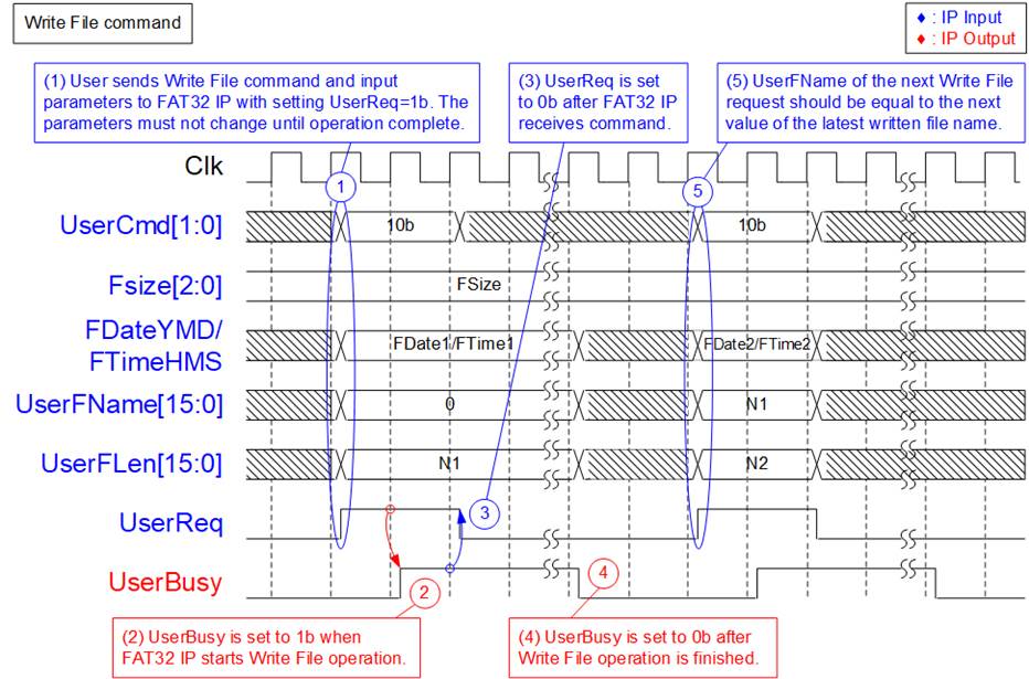
Figure 7: Timing diagram of Control interface during Write file command operation
The steps of the control interface to execute the Write file command are described below.
1) Set UserCmd = 10b (Write File), along with the following input parameters: FSize (File size), FDate (created date), FTime (created time), UserFName (the first file name to write), and UserFLen (total number of written files). Also, set UserReq to 1b to request the Write file command. For the first file after a Format command, set UserFName to 0.
2) The FAT32 IP initiates the Write file command operation based on the user input parameters and sets UserBusy to 1b.
3) De-assert UserReq to 0b to complete the current request. Then, user logic waits until the Write file operation is finished by monitoring UserBusy. During the Write file operation, the data interface of FAT32 IP transfers data from user logic to the NVMe IP until the end of data transfer.
4) Once the Write file command is completed, UserBusy is de-asserted to 0b. The new files are stored in the SSD and the created date and time of all new files are configured using FDateYMD and FTimeHMS inputs.
5) For the next Write file command, UserFName should be set to the next value after the latest written file. If the number of files in the first Write file command is N1, the UserFName for the next Write file command should be set to N1. However, FDate and FTime inputs can be changed for the new Write file command.
The results after executing the two Write file commands in Figure 5 are as follows.
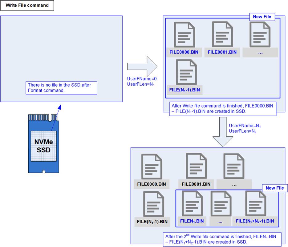
Figure 8 New files are created after finishing Write file operation
Upon completion the execution of the first Write file command, the files FILE0000.BIN to FILE (N1 – 1).BIN are stored in the SSD. The next Write command is configured to create the new files which are sequentially named from the previous Write file command, starting from FILEN1.BIN to FILE(N1 + N2 – 1).BIN.
Note: Each file name follows the format FILEXXXX.BIN, where “XXXX” represents a four-digit hexadecimal number, starting from FILE0000.BIN. The subsequent files are named incrementally.
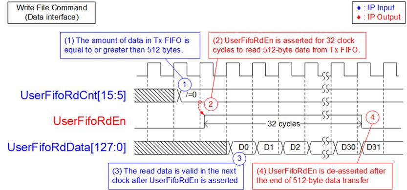
Figure 9: TX FIFO Interface for Write command
Figure 9 illustrates the timing diagram of data interface during the Write file command operation. The following steps outline this process.
1) Data is transferred in burst size of 512 bytes. Before initiating each 512-byte data transfer, the value of UserFifoRdCnt[15:5] is checked to ensure that at least 512 bytes of data are available in Tx FIFO.
2) When UserFifoRdCnt[15:5] is not equal to 0, UserFifoRdEn is asserted to 1b for 32 clock cycles.
3) UserFifoRdData must be valid in the next clock cycle after asserting UserFifoRdEn to 1b. All 32 data are read continuously.
4) Once all 512-byte data transfer is completed, UserFifoRdEn is de-asserted to 0b. If there is remaining data to be transferred, the process returns to step 1) for the next data transfer. Otherwise, the IP returns to Idle state.
Note: The amount of data to be transferred for each file can be determined by multiplying the value of UserFLen by the file size.
Read File command
The Read file command allows the user to read data from the FAT32 IP by setting the input parameters through the control interface and then the data is returned to the user logic via the data interface.

Figure 10: Timing diagram of control interface during Read file command
The steps of the control interface to execute the Read file command are described below.
1) Set UserCmd = 11b (Read File), along with the input parameters: FSize (File size), UserFName (the first file name to read), and UserFLen (total number of read files). Also, set UserReq to 1b to request the Read file command.
Note: Ensure that UserFName + UserFLen is less than or equal to the value of TotalFCap (the maximum number of files in the SSD).
2) The FAT32 IP initiates the Read file command operation based on the user input parameters and sets UserBusy to 1b.
3) De-assert UserReq to 0b to complete the current request. Then, user logic waits until the Read file operation is finished by monitoring UserBusy. During the Read file operation, the data interface of FAT32 IP transfers data from the NVMe IP to user logic until the end of data transfer.
4) Once the Read file command is completed, UserBusy is de-asserted to 0b.
The data interface for transferring data from the NVMeIP to user logic during the Read file command is illustrated on Figure 11.
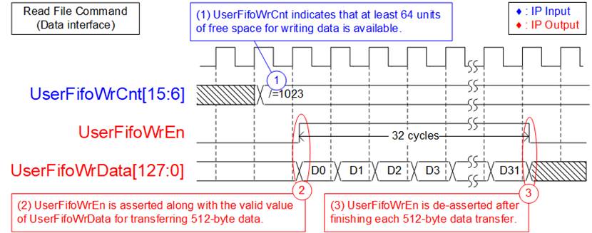
Figure 11: RX FIFO Interface for Read file command
For Read file command, UserFifoWrEn is asserted to 1b along with the valid UserFifoWrData to transmit data to the user logic through the FIFO interface.
1) Before initiating each 512-byte data transfer, UserFifoWrCnt[15:6] is checked to ensure that at least 64 units of free space for writing data is available. This condition is indicated by UserFifoWrCnt[15:6] ≠ all one or 1023).
2) UserFifoWrEn is asserted to 1b continuously for 32 clock cycles to transfer 512-byte data from the NVMe IP to user logic.
3) Once all 512-byte data transfer is completed, UserFifoWrEn is de-asserted to 0b. If there is additional data to be transferred, the process returns to step 1) to continue the next 512-byte data transfer.
Similar to the Write file command, the amount of data to be transferred for each file can be determined by multiplying the value of UserFLen by the file size.
Error
If there is any error found during the operation, UserError signal is asserted to 1b. The type of error is indicated by UserErrorType signal. To clear the error, it must assert RstB to 0b, as shown in Figure 12.

Figure 12: Error flag timing diagram
Limitation
Please ensure the following considerations are met when using the FAT32 IP.
1) Formatting of the NVMe SSD: It is essential to format the NVMe SSD using the FAT32 IP. The maloperation or incorrect information of TotalFCap may be happened if the SSD is not formatted by FAT32 IP.
2) Exclusive write access: All files stored on the NVMe SSD must be written by FAT32 IP. Using other hosts to write files to the SSD can lead to system malfunctions.
3) Read-only access by other hosts: Other hosts are allowed to access NVMe SSD by read-only mode.
4) Uniform file sizes: All files stored on the NVMe SSD must have the same size, defined by FSize during the operation. To change FSize value, it requires reformatting the SSD with the updated FSize value.
5) Write file command considerations: Ensure that the UserFName represents the next value after the latest written file.
a) If UserFName value is more than the latest written file, the new written file will be lost and the free space of the SSD will be incorrect.
b) If UserFName value is less than the latest written file, the data of the new file will replace the contents of the existing file with the matching file name.
Verification Methods
The FAT32 IP Core for NVMe functionality was verified by simulation and also proved on real board design by using ZC706/KCU105/ZCU106 boards.
Recommended Design Experience
Experience design engineers with a knowledge of Vivado Tools should easily integrate this IP into their design.
Ordering Information
This product is available directly from Design Gateway Co., Ltd. Please contact Design Gateway Co., Ltd. for pricing and additional information about this product using the contact information on the front page of this datasheet.
Revision History
|
Revision |
Date |
Description |
|
2.0 |
27-Jun-2023 |
Support ZCU106, add Shutdown command, and update NVMe IP interface. |
|
1.1 |
9-May-2018 |
Correct information |
|
1.0 |
8-Nov-2017 |
Initial Release |