FTP 10G Server Demo reference design
Rev1.2 11-Aug-23
1.1 FTP Connection Establishment and User Authentication
1.2 FTP Data Connection Management by Passive Mode
2.1 10/25Gb Ethernet PCS/PMA (BASE-R)
2.3 TenGMacIF (only when using Xilinx EMAC IP)
Transmitted data (NVMe2TOEFifo)
3.1 FTP command without data connection
3.2 FTP command with data connection
3.3 Function List in Test Firmware
3.3.3 Function for ftp operation
1 Introduction
File Transfer Protocol (FTP) is a standard network protocol used for file transmission between a client and server on a network. For the reliable and efficient transmission, TCP/IP is used as lower layer.
Reference documents
1. File Transfer Protocol: http://tools.ietf.org/html/rfc959
2. File Transfer Protocol: http://www.tcpipguide.com/free/t_FileTransferProtocolFTP.htm
3. FTP Sequence: www.eventhelix.com/realtimemantra/networking/FTP.pdf
4. List of FTP commands: http://en.wikipedia.org/wiki/List_of_FTP_commands
5. List of FTP server return codes: http://en.wikipedia.org/wiki/List_of_FTP_server_return_codes

Figure 1‑1 Model of FTP Use
In the model described in Figure 1‑1, there are two hosts with their own data storage. One is server with shared data in the network and another is client for general users who can authenticate themselves with sign-in protocol, normally in form of username and password. For this protocol, two connections are required, i.e., control connection for FTP command and FTP replies transferring between client and server and data connection for data transmission between two hosts.
Control connection is taken responsibility by the server-protocol interpreter (Server-PI) and the user-protocol interpreter (User-PI). The server-PI listens on its own port number (Port 21 is used since it is a well-known control port) until the connection is established. After that, Server-PI waits FTP commands from User-PI, returns standard FTP replies over the control connection in response of the command, and manages the server data transfer process (Server-DTP) when the command needs data transfer. For client side, User-PI is responsible to forward the command received from the user interface to Server-PI, wait FTP replies, and manage the user data transfer process (User-DTP) when the command needs data transfer.
Data connection is taken responsibility by the server data transfer process (Server-DTP) and the user data transfer process (User-DTP) for sending or receiving data. The data connection establishment can be done by Server-DTP (active mode) or User-DTP (passive mode). Passive mode is commonly used to resolve the firewall problem on FTP client. The data connection is established to transfer information or files between the server and the client. The data connection is terminated after finishing information or file transferring. Both Server-DTP and User-DTP interact with the local file system when reading or writing files.
User Interface provides the interface for a person requiring to obtain file transfer service through the FTP software. The command is issued and the response is checked.
More details to transfer data between Server and Client by using FTP protocol are described as belows.
1.1 FTP Connection Establishment and User Authentication
After user creates the connection on control port, the next process is user authentication. FTP server can be accessed by authorized user only. The details of the connection establishment and login process are described as follows.

Figure 1‑2 Connection Establishment on Control port
According to Transmission Control Protocol (TCP), 3-Way Handshake process is the way to establish the connection, as shown in Figure 1‑2. FTP client starts sending TCP packet with SYN flag to server on Port 21 to be the request for creating the new connection. After this packet is detected by FTP Server, the server returns the TCP packet with SYN and ACK flag to allow the new connection creating. Finally, client sends acknowledgement (ACK flag) to finish this process and the control port is in ready status for server and client communication. The control port is applied for transferring FTP commands and replies.

Figure 1‑3 User Authentication
As shown in Figure 1‑3, after the connection was established, the authorized users have to identify themselves with allowed username and password. For user authentication, client sends two FTP commands which are USER command with username and PASS with password respectively. Finally, the server replies the client with FTP response 230 to allow opening the new session.
1.2 FTP Data Connection Management by Passive Mode
This reference design implements the data connection establishment by Client (Passive mode) which is generally used. So, only the step for running as Passive mode is described in this topic.
Some FTP commands, e.g., LIST (List subdirectories or files), STOR (Store files), and RETR (Retrieve files) must transfer information or file through the data connection. Before transferring data in previously mentioned commands, PASV command is firstly sent from client to specify the parameters for the data connection, i.e., IP address and port number of Server-DTP.
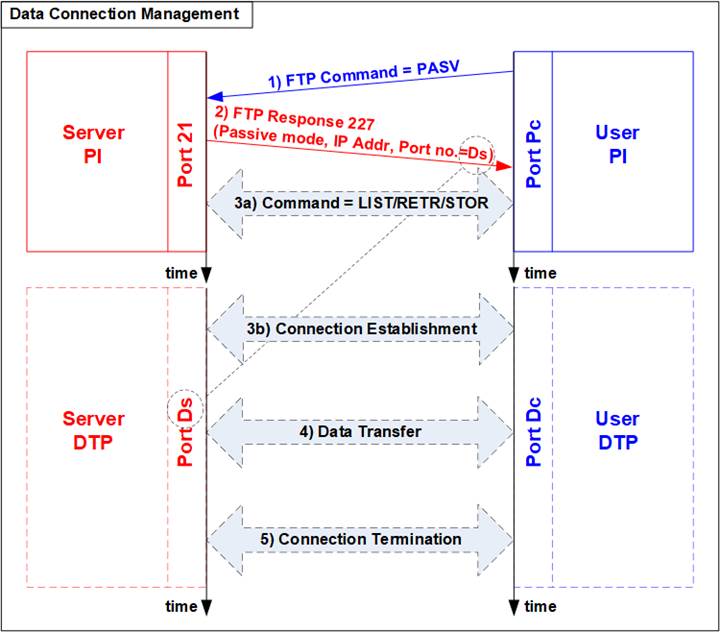
Figure 1‑4 Data Connection Management in Passive Mode
After receiving PASV command, the server returns FTP response 227 to inform IP address and port number of Server to Client. Assume the data port number of the server is equal to Ds. Server-PI instructs Server-DTP to listen on Port Ds and wait for data connection establishment. Next, User-PI sends FTP command which requires data transfer to Server-PI. At the same time, User-DTP establishes the data connection to transfer data with Server-DTP. The sequence of Step 3a) for transferring FTP command and step 3b) for the data connection establishment can be swapped, depending on FTP client behavior. When the data transfer is finished, the data connection is terminated by the side transmitting data.
1.3 LIST Command
The LIST command is issued to transfer information about files in the specified directory, stored on the server�s side, through an established data connection. PASV command is sent firstly to initialize the data connection. After that, User-PI sends LIST command to Server-PI and User-DTP establishes data connection at the same time. The sequence of Step 2a) for transferring FTP command and step 2b) for the data connection establishment is possibly swapped.

Figure 1‑5 LIST Command Operation
For the server side, after the data connection was established, Server-PI returns response 125 for LIST command and Server-DTP returns information of files or the list of files to client. When the data transfer is finished, Server-DTP terminates the data connection. Finally, Server-PI sends response 226 to complete LIST command operation.
1.4 STOR Command
The STOR command is issued by client when the user requires to upload a copy of a file to store on the server�s storage. The client provides the file name for uploading with the STOR command. If the file already exists on the server, it is replaced by the uploaded file. Otherwise, the uploaded file is created. Next, the server decodes file name to be a parameter to store a file. After that, data transmission begins, similar to the operation of LIST command. Data transfer direction is opposite from LIST and RETR command by sending from User-DTP (client) to Server-DTP (server). User-DTP terminates the data connection after finishing all data transmission.
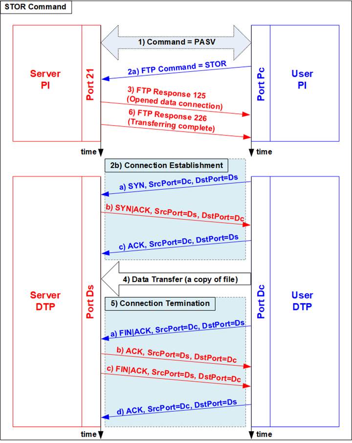
Figure 1‑6 STOR Command Operation
1.5 RETR Command
The RETR command is sent from the client when user requires to download a copy of a file on the server. The client provides the file name along with the RETR command. On the server side, after the file name is decoded, the data of the requested file is returned. The step of data sequence is similar to LIST command. The data connection is released by Server-DTP after the data transfer is completed.
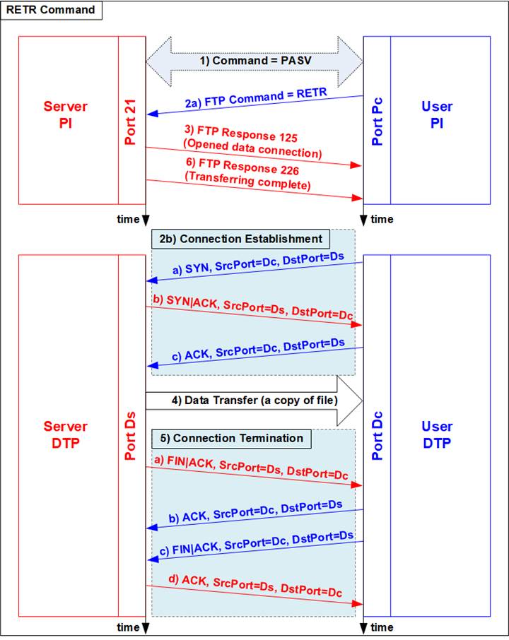
Figure 1‑7 RETR Command Operation
2 Hardware Structure

Figure 2‑1 Demo Block Diagram
As described in the introduction, at least two connections are necessary for running FTP protocol, i.e., control connection for transferring FTP command and response and data connection for transferring data in some FTP commands such as LIST, STOR, and RETR command.
The control connection is handled by CPU system for creating and decoding Ethernet packet with 10G/25G Ethernet MAC via UserMAC. UserMAC forwards FTP command sent by FTP client to CPU for decoding and then returns FTP response from CPU to 10G/25G Ethernet MAC. UserMAC is mapped to TOEReg to allow CPU access via AXI4-Lite bus. To operate data connection, both TOEReg and exFATReg are accessed by CPU.
The data connection is handled by TOE10G-IP which is integrated inside TopTCP10G. The data source of TOE10G-IP has two sources. First is file information, created by CPU system, when operating LIST command. Second is data in the requested file, read from NVMe SSD by exFATNVMe module, when operation RETR command. The received data in the data connection is directly connected to exFATNVMe module for operating STOR command.
By using TOE10G-IP operating with exFAT for NVMe block which consists of exFAT-IP and NVMe(G3)-IP, data transferring in FTP demo achieves the best performance on 10G Ethernet speed. Though exFAT for NVMe performance is equal to NVMe PCIe Gen3 device speed (about 3300 MB/s), the performance in the demo is limited by 10 Gb Ethernet speed which has maximum speed about 1200 MB/s.
More details of the hardware inside the demo are described in this topic.
2.1 10/25Gb Ethernet PCS/PMA (BASE-R)
10/25Gb PCS/PMA implements physical layer of 10G Ethernet. It connects to the external hardware which is 10G BASE-R SFP+ module. The user interface is 64-bit XGMII interface
running at 156.25 MHz for connecting with Ethernet MAC. This IP core is provided by Xilinx without the charge. More details of the core are described in the following link.
10G (10G/25G) Ethernet PCS/PMA (BASE-R)
https://www.xilinx.com/products/intellectual-property/10gbase-r.html
https://www.xilinx.com/products/intellectual-property/ef-di-25gemac.html
2.2 10G/25G Ethernet MAC
10G/25G EMAC connects between TOE10G-IP and 10G/25G PCS/PMA module. The interface with TOE10G-IP is 64-bit AXI4 stream while the interface with 10G/25G PCS/PMA module is 64-bit XGMII interface at 156.25 MHz.
When using DG 10G25GEMAC-IP, TOE10G IP can connect to EMAC IP directly, as shown in Figure 2‑2. More details about DG 10G25GEMAC-IP are described in the following link.
https://dgway.com/products/IP/GEMAC-IP/dg_10g25gemacip_data_sheet_xilinx.pdf
When connecting with Xilinx 10G/25G EMAC-IP, the small buffer must be connected between TOE10G-IP and Xilinx 10G/25G EMAC-IP. So, TenGMacIF module is designed to be the Tx interface module. More details of TenGMacIF are described in the next topic. The details of Xilinx EMAC are described in the following link.
https://www.xilinx.com/products/intellectual-property/do-di-10gemac.html
https://www.xilinx.com/products/intellectual-property/ef-di-25gemac.html
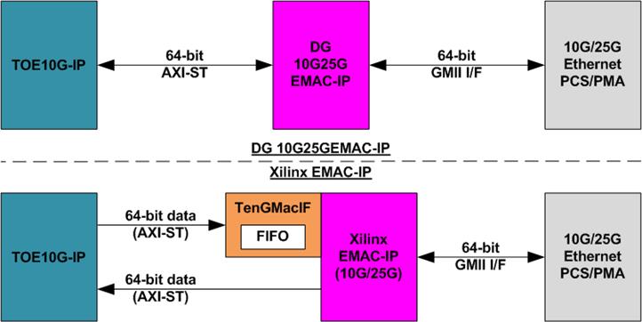
Figure 2‑2 TOE10G-IP with EMAC-IP connection
2.3 TenGMacIF (only when using Xilinx EMAC IP)
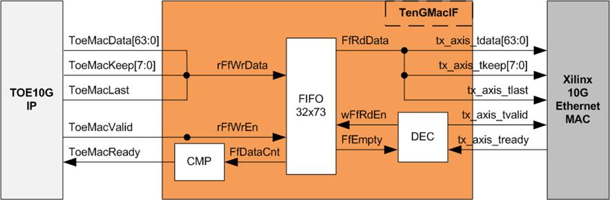
Figure 2‑3 TenGMacIF Block Diagram
Tx interface timing diagram of Xilinx 10G/25G EMAC and TOE10G-IP are different. TOE10G-IP needs to send data of one packet continuously, but Xilinx EMAC does not support this feature. Xilinx EMAC may de-assert ready signal to pause data receiving before end of the packet. TenGMacIF is designed to store transmitted data from TOE10G-IP when Xilinx 10G/25G EMAC is not ready to receive new data. According to real-board testing, tready output from Xilinx 10G EMAC is not de-asserted for long time per packet, so small FIFO which has 32-data depth is included to store the data during pausing time.
The operation of TenGMacIF is split into two sides, following the interface, i.e., Writing FIFO and Reading FIFO. Timing diagram for writing FIFO from TOE10G-IP is shown in Figure 2‑4 while timing diagram for reading FIFO and forwarding to Xilinx 10G EMAC is shown in Figure 2‑5.
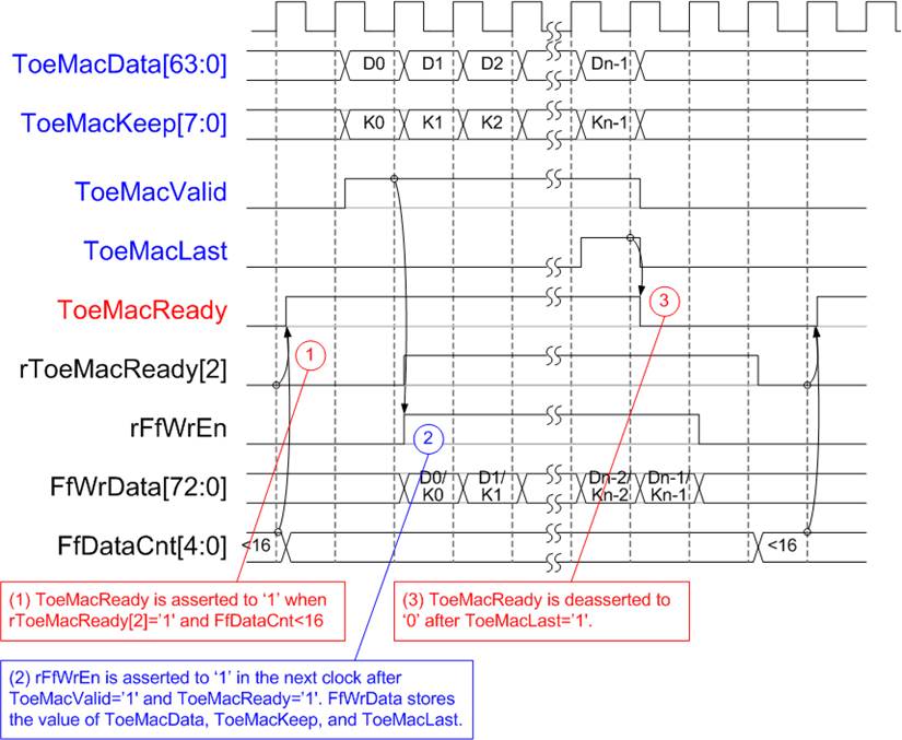
Figure 2‑4 Write FIFO timing diagram of TenGMacIF
(1) Before asserting ToeMacReady to �1� for receiving the new data, two conditions must be met.
a) The logic checks if free space in FIFO is more than 16 by monitoring when FfDataCnt is less than 16.
Note: By real-board monitoring, it is found that Xilinx 10G/25G EMAC-IP de-asserts tx_axis_tready to �0� less than 16 cycles for each packet.
b) The previous packet is completely transferred more than two clock cycles by checking rToeMacReady[2]=�0�. rToeMacReady[2] is created by ToeMacReady with two clock cycle latency time. To pause the packet transmission, ToeMacReady is de-asserted to �0� to wait until EMAC and TenGMacIF is ready.
(2) During packet transmission, ToeMacValid from TOE10G-IP and ToeMacReady are asserted to �1� continuously until end of packet, so the packet is transferred without pausing time. In the next clock after ToeMacReady and ToeMacValid are asserted to �1�, rFfWrEn is asserted to �1� to store received data. FIFO data size is 73-bit for storing 64-bit data (ToeMacData), 8-bit of byte enable (ToeMacKeep), and last flag (ToeMacLast).
(3) When the last data is received (ToeMacLast=�1�), ToeMacReady is de-asserted to �0� for 3 clock cycles to be the gap size for each packet transmission.
Timing diagram to forward data from FIFO to Xilinx 10G EMAC is shown in Figure 2‑5.
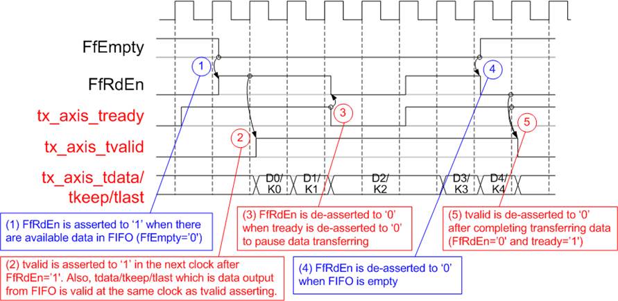
Figure 2‑5 Read FIFO timing diagram of TenGMacIF
(1) When the new packet is received from TOE10G-IP, FIFO empty (FfEmpty) is de-asserted to �0�. Since the packet from TOE10G-IP is transferred continuously, FIFO is not empty until a packet is completely transferred. The logic asserts read enable of FIFO (FfRdEn) to �1� for reading data from FIFO and forwarding data to Ethernet MAC.
(2) After reading data from FIFO, tx_axis_tvalid is asserted to �1� with the valid data for transferring to EMAC in the next cycle.
(3) When EMAC is not ready to receive data (tx_axis_tready=�0�), read enable must be de-asserted to �0� to pause data transmission.
(4) After the packet is completely transferred, the FIFO shows empty status (FfEmpty=�1�). At the same time, FfRdEn is de-asserted to �0� to stop data transmission.
(5) Next, tx_axis_tvalid is de-asserted to �0� to finish the packet transmission.
2.4 TopTCP10G

Figure 2‑6 TopTCP10G block diagram
TopTCP10G is the module for transferring data with 10G/25G Ethernet MAC (10G/25GEMAC). To run FTP server application, two ports are implemented on the hardware. First is control connection and another is data connection. The control connection is responsible to decode FTP command and return FTP response. Control connection uses small packet size and transfers less frequently. Therefore, this port is implemented by using UserMAC controlled by CPU which is low-speed channel. While data connection that is applied to transfer the data in RETR (file), STOR (file), and LIST (list of files) command requires high bandwidth to support big data size. Therefore, this port is implemented by using TOE10G-IP to achieve high-speed performance. The data source of TOE10G-IP is selected between LAxi2Reg and exFATNVMe. List of files of LIST command is prepared by CPU through LAxi2Reg while file data of RETR command is read from SSD by exFATNVMe.
While Tx packet output from UserMAC and TOE10G-IP are selected by the switch logic for sending to EMAC, the received interface of EMAC is connected to both UserMAC and TOE10G-IP directly. There is filter logic inside UserMAC and TOE10G-IP to check the port number in the header before operating. Therefore, the received packet of control port is operated by UserMAC while the received packet of data port is operated by TOE10G-IP.
There are two clock domains inside TopTCP10G, NVMeClk (interface with exFATNVMe) and TOEClk (interface with 10G/25GEMAC). Therefore, asynchronous FIFOs are included to support clock domain crossing and convert data bus size between TOE10G-IP (64-bit) and exFATNVMe (128-bit). NVMe2TOEFifo forwards the read data returned from the SSD to TOE10G-IP while TOE2NVMeFifo forwards the received data from TOE10G-IP to write to SSD.
TOE10G-IP
TOE10G-IP implements TCP/IP stack and offload engine. Control and status signals for user interface are accessed through register interface. Data interface is accessed through FIFO interface. More details are described in datasheet.
https://dgway.com/products/IP/TOE10G-IP/dg_toe10gip_data_sheet_xilinx_en.pdf
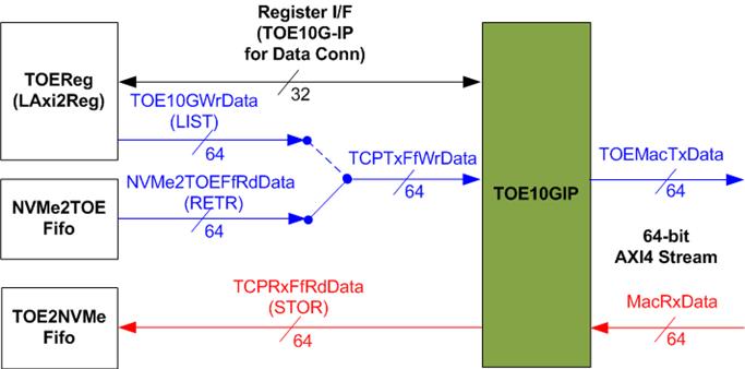
Figure 2‑7 TOE10G-IP interface for data connection
In this demo, TOE10G-IP is applied for transferring data of data connection at high-speed rate. The network parameters of TOE10G-IP are set by CPU through LAxi2Reg to run as data connection of FTP command.
In transmit path, the data from TOEReg or NVMe2TOEFifo is forwarded to Tx FIFO interface of TOE10G-IP. Total amount of transmitted data is calculated by CPU. Also, CPU sets total transmit size to TOE10G-IP before starting sending data for LIST and RETR FTP command.
In received path, there is no need to calculate the data size. All received data from TOE10G-IP is forwarded to TOE2NVMeFifo when the FIFO is not full. CPU reads TOE10G-IP register for status monitoring. Next topic describes more details of data interface for transmitted data and received data.
Transmitted data (NVMe2TOEFifo)

Figure 2‑8 Transmitted data of TOE10G-IP
To transmit data to client through TOE10G-IP, there are two data sources, i.e., the list of file name stored in the SSD written by CPU firmware and the data of the file returned from the SSD through exFATNVMe, as shown in Figure 2‑8.
To transfer the data of the file in RETR command, the step for transferring data from FIFO to TOE10G-IP is described as follows.
(1) The hardware must ensure that NVMe2TOEFifo has remaining data (NVMe2TOEFfEmpty=�0�), Tx FIFO of TOE10G-IP is not full (TCPTxFfFull=�0�), and the data connection establishment is completed (ConnOn=�1�). After that, asserts read enable of NVMe2TOEFifo (NVMeTOEFfRdEn=�1�).
(2) The read data from FIFO (NVMe2TOEFfRdData) is ready to forward to TOE10G-IP in the next clock. So, write enable to TOE10G-IP (TCPTxFfWrEn) is asserted after NVMeTOEFfRdEn is asserted with one clock latency time.
To transfer file name in LIST command, the design allows CPU to write data to TOE10G-IP directly by asserting TOE10GWrEn and assigning TOE10GWrData.
The FIFO is generated for supporting independent clock and asymmetric port width. The size is 64 Kbytes. exFATFifoWrCnt is monitored by exFATNVMe module to check the free space size in the FIFO. When the free space is much enough and data of the SSD is ready, 512-byte data is sent to NVMe2TOEFifo.
Received data (TOE2NVMeFifo)
Figure 2‑9 Received data of TOE10G-IP
The data read from client through TOE10G-IP is stored to TOE2NVMeFifo when operating STOR command. Data of the file received from FTP client is stored to the SSD through exFATNVMe. exFATFifoRdCnt and exFATFifoEmpty are monitored to check the amount of data in FIFO before forwarding to the SSD.
TOE2NVMeFifo is also generated for supporting independent clock and asymmetric port width. Similar to NVMe2TOEFifo, the size is 64 Kbytes, but the data path is reversed.
2.5 UserMAC
Figure 2‑10 UserMAC Block Diagram
UserMAC is responsible to transfer TCP/IP packet for FTP control connection. The step of FTP control connection is designed by CPU firmware to access UserMAC registers through TOEReg module. Data interface of UserMAC with TOEReg is 32-bit RAM standard while data interface with 10G/25GEMAC is 64-bit AXI4 Stream standard.
UserMAC consists of two modules, i.e., UserTxMAC and UserRxMAC. UserTxMAC includes TxRAM which stores the data written by CPU to 10G/25GEMAC. UserRxMAC includes RxRAM which stores the received packet from 10G/25GEMAC. The header of received packet has been verified by the packet filtering logic before stored to RxRAM. More details of UserTxMAC and UserRxMAC are described as follows.
2.5.1 UserTxMAC

Figure 2‑11 UserTxMAC Logic Diagram
The step to transfer the packet from TxRAM to EMAC is as follows.
(1) CPU checks that UserTxBusy=�0� to confirm UserTxMAC is in Idle state.
(2) CPU writes transmit packet to TxRAM, starting from the 1st address (TxRamWrAddr=0).
(3) CPU sets UserTxLen=Packet size while asserting UserTxReq to �1� to begin data transmission.
(4) UserTxBusy is asserted to �1� during transmitting data. At the same time, Counter loads total transfer size and starts counting to control packet size. AddressCalUnit resets the read address (wTxRamRdAddr) to 0 for reading the data starting from the 1st address. Read data of TxRAM (UserTx10GMACData) is valid after the read address is valid with 1-clock latency time. The read data is applied to send to EMAC directly.
(5) UserTx10GMACValid is asserted to �1� to send the data along with UserTx10GMACData.
(6) Wait until UserTx10GMACReady is asserted to �1� to confirm that the 1st data of the packet is accepted. After that, the next data is read from TxRAM and sent to 10G/25GEMAC continuously until end of the packet. At the same time, UserTx10GMACKeep is always set to all �1�.
(7) After the counter to show the remaining transfer size of each packet (rLenCnt) is equal to 2, showing that the final data of the packet is ready to transfer, UserTx10GMACKeep value reads rLastLen to generate the byte valid of the final data which may be equal to 0x01 (1-byte), 0x03 (2-byte), 0x07 (3-byte), 0x0F (4-byte), 0x1F (5-byte), 0x3F (6-byte), 0x7F (7-byte), or 0xFF (8-byte). UserTx10GMACLast is also asserted to �1� for sending the final data of a packet.
(8) After that, UserTx10GMACValid and UserTxBusy are de-asserted to �0�.
2.5.2 UserRxMAC
Figure 2‑12 UserRxMAC Logic Diagram
The step when the new packet is received from EMAC is as follows.
(1) a) When the first data of the packet is detected, the enable signal to compare 38-byte header of each packet is asserted to �1� for 5 clock cycles (one clock cycle can compare 8-byte data).
b) At the same time, the address counter (AddrCounter) for generating write address of RxRAM (rRxRamWrAddr) loads the latest position of valid packet from rLastAddrLat. After that, the write address is increased to store the next data to the next address of RxRAM.
c) The received packet is stored to RxRAM by using UserRx10GMACValid to be write enable of RxRAM and UserRx10GMACData to be write data.
(2) Byte#0 � #37 of received data (UserRx10GMACData) are fed to header comparator module (HeaderCmp) to compare with the expected value (UserRxHdData), set by CPU firmware. UserRxHdValid is enable/disable flag to compare each byte of the header. Bit0 of UserRxHdValid is byte0 enable, bit1 is byte1 enable, and so on.
(3) When the final data of the packet is received (UserRx10GMACLast=�1�), the header result flag (rHdOK) are read. When all headers are valid (rHdOK=all �1�), rLastAddrValid is asserted to �1�. At the same time, the latest address (rRxRamWrAddr) is loaded to rLastAddrLat to update the latest position of valid packet. Otherwise, rLastAddrLat is not updated and the current packet will be replaced by the new packet.
(4) CPU reads FIFO count (UserRxMacFfCnt) to check if the new packet is received (UserRxMacFfCnt is not equal to 0). Next, CPU asserts read enable (UserRxMacFfRdEn) to read the end address for storing the final data of each packet (UserRxMacFfRdData). After that, CPU reads and decodes each received packet until the read address (UserRxRamRdAddr) is equal to the last address. Step (4) is repeated until FIFO count is equal to 0.
Note: UserRxRamRdAddr is the address for 32-bit data while rRxRamWrAddr is the address for 64-bit data. So, CPU firmware must convert the 64-bit address to 32-bit address before starting reading data from RxRAM.
The 38-byte header of received packet for control connection of FTP application is shown as Figure 2‑13.
Figure 2‑13 TCP/IP Packet header for FTP application
HeaderCmp is the packet filtering module which is controlled by CPU firmware. 38-byte header is verified by the set value from CPU. In the demo, CPU firmware assigns the enable flag and the verification value to compare six parameters as follows (blue color in Figure 2‑13).
1) Ethernet Type (2 bytes) = 0x0800 (IPv4)
2) IP version (1 byte) = 0x45 (Version 4)
3) Protocol (1 byte) = 0x06 (TCP Protocol)
4) Source IP Address (4 bytes) = IP address of FTP client
5) Destination IP Address (4 bytes) = IP address of FPGA
6) Destination Port Number (2 bytes) = 0x0015 (Port 21)
When the header of the packet is matched to the above parameters, the received packet is stored to RxRAM for CPU processing. Otherwise, the packet is ignored.
2.6 exFATNVMe

Figure 2‑14 exFATNVMe Block Diagram
exFATNVMe is exFAT-IP core for NVMe SSD which consists of exFAT-IP and NVMe(G3)-IP. More details of exFAT-IP are described in the data sheet.
https://dgway.com/products/IP/NVMe-IP/dg_exfatip_nvme_data_sheet_en.pdf
In FTP 10G demo system, the control interface for setting file parameters is controlled by CPU through exFATReg inside LAxi2Reg module. The data interface (FIFO standard) is connected to TopTCP10G to transfer data with TOE10G-IP.
2.7 CPU and Peripherals
32-bit AXI4-Lite is applied to be the bus interface for the CPU accessing the peripherals such as Timer and UART. To control and monitor the test system, the control and status signals are connected to register for CPU access as a peripheral through 32-bit AXI4-Lite bus. CPU assigns the different base address and the address range to each peripheral for accessing the internal registers of the peripheral.
In the reference design, the CPU system is built with two additional peripherals to access the two hardware systems. First is applied to control Ethernet system which is run under TOEClk. Second is applied to control exFAT system which is run under NVMeClk. The interface logic must support AXI4-Lite bus standard to allow CPU access for both writing and reading direction, designed by LAxi2Reg as shown in Figure 2‑15.

Figure 2‑15 LAxi2Reg Block diagram
In Figure 2‑15, LAxi2Reg consists of three modules, i.e., AsyncAXIReg, TOEReg, and exFATReg. Two AsyncAXIReg modules are included in the system for supporting two clock domains, TOE clock domain and NVMe clock domain. The function of AsyncAXIReg is to convert 32-bit AXI4-Lite interface in CPU clock domain to register interface in the local clock domain, (TOEClk and NVMeClk). AXI4-Lite is the standard interface for CPU. Another side of AsyncAXIReg connects to TOEReg and exFATReg which include the register file of the parameters and the status signals for UserMAC and exFATNVMe respectively. More details of each module are described as follows.
2.7.1 AsyncAXIReg

Figure 2‑16 AsyncAXIReg Interface
The signal on AXI4-Lite bus interface can be split into five groups, i.e., LAxiAw* (Write address channel), LAxiw* (Write data channel), LAxiB* (Write response channel), LAxiAr* (Read address channel), and LAxir* (Read data channel). More details to build custom logic for AXI4-Lite bus is described in following document.
According to AXI4-Lite standard, the write channel and the read channel are operated independently. Also, the control and data interface of each channel are run separately. So, the logic inside AsyncAXIReg to interface with AXI4-Lite bus is split into four groups, i.e., Write control logic, Write data logic, Read control logic, and Read data logic as shown in the left side of Figure 2‑16. Write control I/F and Write data I/F of AXI4-Lite bus are latched and transferred to be Write register interface with clock domain crossing registers. Similarly, Read control I/F of AXI4-Lite bus are latched and transferred to be Read register interface. While the returned data from Register Read I/F is transferred to AXI4-Lite bus by using clock domain crossing registers. In Register interface, RegAddr is shared signal for write and read access. Therefore, it loads the value from LAxiAw for write access or LAxiAr for read access.
The simple register interface is compatible with single-port RAM interface for write transaction. The read transaction of the register interface is slightly modified from RAM interface by adding RdReq and RdValid signals for controlling read latency time. The address of register interface is shared for write and read transaction, so user cannot write and read the register at the same time. The timing diagram of the register interface is shown in Figure 2‑17.
Figure 2‑17 Register interface timing diagram
1) To write register, the timing diagram is similar to single-port RAM interface. RegWrEn is asserted to �1� with the valid signal of RegAddr (Register address in 32-bit unit), RegWrData (write data of the register), and RegWrByteEn (the write byte enable). Byte enable has four bits to be the byte data valid. Bit[0], [1], [2] and [3] are equal to �1� when RegWrData[7:0], [15:8], [23:16] and [31:24] are valid respectively.
2) To read register, AsyncAXIReg asserts RegRdReq to �1� with the valid value of RegAddr. 32-bit data must be returned after receiving the read request. The slave must monitor RegRdReq signal to start the read transaction. During read operation, the address value (RegAddr) does not change the value until RegRdValid is asserted to �1�. Therefore, the address can be used for selecting the returned data by using multiple layers of multiplexer.
3) The read data is returned on RegRdData bus by the slave with asserting RegRdValid to �1�. After that, AsyncAXIReg forwards the read value to LAxir* interface.
2.7.2 TOEReg
Figure 2‑18 TOEReg Block diagram
TOEReg includes the registers of the modules processing Ethernet packet such as TOE10G-IP within TopTCP10G, UserTxMAC, and UserRxMAC. The address range is split into seven areas.
1) 0x0000 � 0x00FF: mapped to TOE10G-IP register for setting and monitoring network parameters and control signals.
2) 0x1000: mapped to write TCP data which is the list of file name, sent to TOE10G-IP for LIST command.
3) 0x2000 � 0x2FFF: mapped to the control/status signals of UserTxMAC for transmitting packet.
4) 0x3000 � 0x3FFF: mapped to write TxRAM which stores Tx packet of FTP control connection. This area is write-access only.
5) 0x4000 � 0x4FFF: mapped to read RxRAM which stores Rx packet of FTP control connection. This area is read-access only.
6) 0x5000 � 0x5FFF: mapped to the control/status signals of UserRxMAC for receiving packet.
7) 0x6000 � 0x6FFF: mapped to read the status signal, output from TOE10G-IP. This area is read-access only.
Address decoder decodes the upper bit of RegAddr for selecting the active hardware. To read register, three-step multiplexers are designed to select the read data, returned to CPU. The latency of read data is equal to three clock cycles, so RegRdValid is created by RegRdReq with asserting three D Flip-flops. More details of the address mapping within TOEReg module are shown in Table 2‑1.
Table 2‑1 Memory Map of TOEReg
|
Address |
Register Name |
Description |
|
Wr/Rd |
Label in �ftp10cputest.c� |
|
|
BA0+0x0000 - BA0+0x00FF: TOE10G-IP Register Area More details of each register are described in TOE10G-IP datasheet |
||
|
BA0+0x0000 |
TOE_RST_INTREG |
Mapped to RST register within TOE10G-IP |
|
BA0+0x0004 |
TOE_CMD_INTREG |
Mapped to CMD register within TOE10G-IP |
|
BA0+0x0008 |
TOE_SML_INTREG |
Mapped to SML register within TOE10G-IP |
|
BA0+0x000C |
TOE_SMH_INTREG |
Mapped to SMH register within TOE10G-IP |
|
BA0+0x0010 |
TOE_DIP_INTREG |
Mapped to DIP register within TOE10G-IP |
|
BA0+0x0014 |
TOE_SIP_INTREG |
Mapped to SIP register within TOE10G-IP |
|
BA0+0x0018 |
TOE_DPN_INTREG |
Mapped to DPN register within TOE10G-IP |
|
BA0+0x001C |
TOE_SPN_INTREG |
Mapped to SPN register within TOE10G-IP |
|
BA0+0x0020 |
TOE_TDL_INTREG |
Mapped to TDL register within TOE10G-IP |
|
BA0+0x0024 |
TOE_TMO_INTREG |
Mapped to TMO register within TOE10G-IP |
|
BA0+0x0028 |
TOE_PKL_INTREG |
Mapped to PKL register within TOE10G-IP |
|
BA0+0x002C |
TOE_PSH_INTREG |
Mapped to PSH register within TOE10G-IP |
|
BA0+0x0030 |
TOE_WIN_INTREG |
Mapped to WIN register within TOE10G-IP |
|
BA0+0x0034 |
TOE_ETL_INTREG |
Mapped to ETL register within TOE10G-IP |
|
BA0+0x0038 |
TOE_SRV_INTREG |
Mapped to SRV register within TOE10G-IP |
|
BA0+0x003C |
TOE_VER_INTREG |
Mapped to VER register within TOE10G-IP |
|
BA0+0x1000 - BA0+0x3FFF: Tx interface for EMAC |
||
|
BA0+0x1000 |
Write data to TOE10G-IP |
[31:0] - Transmitted data written by CPU for sending through TOE10G-IP
|
|
Wr |
(TOE_TXDATA_INTREG) |
|
|
BA0+0x2000 |
Total Transmit Length |
Wr: [11:0] - Total transmitted size in byte unit. Valid from 1-0xFFF. UserTxMAC starts transmitting packet after this register is written. Rd: [0] � Busy flag of UserTxMAC. �0�-Idle, �1�-Busy. |
|
Wr/Rd |
(TXEMAC_LEN_INTREG) |
|
|
BA0+0x3000 � BA0+0x3FFF |
TxRAM in UserTxMAC |
Transmitted data written by CPU for sending to UserTxMAC |
|
Wr |
(TXRAM_ADDR_CHARREG) |
|
|
BA0+0x4000 - BA0+0x5FFF: UserRxMAC Area |
||
|
BA0+0x4000 � BA0+0x4FFF |
RxRAM in UserRxMAC |
Received data stored in RxRAM within UserRxMAC |
|
Rd |
(RXRAM_ADDR_CHARREG) |
|
|
BA0+0x5000 � BA0+0x5024 |
UserRxMAC Header Data |
38-byte to set the packet filtering inside UserRxMAC for comparing byte#0 � byte#37 of received packet when header byte enable is asserted to �1�. If header byte enable is de-asserted to �0�, the filter bypasses that byte. 0x5000[7:0] � byte#0, [15:8] � byte#1, [23:16] � byte#2, [31:24] � byte#3 0x5004[7:0] � byte#4, [15:8] � byte#5, [23:16] � byte#6, [31:24] � byte#7 � 0x5020[7:0] � byte#32, [15:8] � byte#33, [23:16] � byte#34, [31:24] � byte#35 0x5024[7:0] � byte#36, [15:8] � byte#37 |
|
Wr |
(RXEMAC_HDVAL_INTREG) |
|
|
BA0+0x5028 � BA0+0x502C |
UserRxMAC Header Byte Enable |
38-bit enable to compare 38-byte header of received packet in UserRxMAC 0x50028[0] � Compare enable of byte#0, [1] � byte#1, �, [31] � byte#31 0x5002C[0] � byte#32, [1] � byte#33, .., [5] � byte#37 |
|
Wr |
(RXEMAC_HDEN_INTREG) |
|
|
BA0+0x5040 |
RxEMAC Last Address |
Wr: Assert read enable for one clock cycle to RxMacFf when this register is written. Please check RXEMAC_FFCNT_INTREG is not equal to 0 before writing this register. Rd: [8:0] � Read the address to store the final data of each packet from RxMacFf. Data can be read after read enable is asserted by writing this register. |
|
Wr/Rd |
(RXEMAC_LASTADDR_ INTREG) |
|
|
BA0+0x5044 |
FIFO Counter of RxMacFf |
[4:0] � FIFO counter to show total amount of data in RxMacFf.
|
|
Rd |
(RXEMAC_FFCNT_INTREG) |
|
|
Address |
Register Name |
Description |
|
Wr/Rd |
Label in �ftp10cputest.c� |
|
|
BA0+0x6000 - BA0+0x7FFF: TOE10G-IP and 10G25GEMAC-IP Status Area |
||
|
BA0+0x6000 |
TOE10G Status Register |
[0] - Reserved [1] - Mapped to ConnOn signal of TOE10G-IP [2] - Mapped to TCPTxFfFull signal of TOE10G-IP |
|
Rd |
(TOEIP_STS_INTREG) |
|
|
BA0+0x6004 |
Interrupt Status of Ethernet interface |
Wr: [0] - Set �1� to clear TimerInt latch value [8] � Set �1� to clear interrupt when RxMacFf is full Rd: [0] � �1�: Detect TimerInt from TOE10G-IP to be asserted to �1�, �0�: Normal [8] � �1�: Detect Full flag of RxMacFf to be asserted to �1�, �0�: Not full |
|
Wr/Rd |
(ETHER_INTSTS_INTREG) |
|
|
BA0+0x6010 |
TenGEMAC-IP Status Register |
[0] � Mapped to linkup signal of DG 10G25GEMAC -IP. (�0�: No link up, �1�: link up) |
|
Rd |
(EMAC_STS_INTREG) |
|
|
BA0+0x6014 |
TenGEMAC-IP Version Reg |
[31:0] � 10G25GEMAC-IP version number, mapped to IPVersion [31:0] of DG 10G25GEMAC -IP |
|
Rd |
(EMAC_VER_INTREG) |
|
2.7.3 exFATReg
Figure 2‑19 exFATReg Block diagram
The address range to map to exFATReg is split into two areas, as shown in Figure 2‑19.
1) 0x0000 � 0x00FF: mapped to set file parameters of exFATNVMe module. This area is write-access only.
2) 0x0100 � 0x08FF: mapped to read the status of exFATNVMe module. This area is read-access only.
Similar to TOEReg, Address decoder decodes the upper bit of RegAddr for selecting the active hardware. The latency of read data is equal to two clock cycles, so RegRdValid is created by RegRdReq with asserting two D Flip-flops. More details of the address mapping within exFATReg module are shown in Table 2‑2.
Table 2‑2 Memory Map of exFATReg
|
Address |
Register Name |
Description |
|
Wr/Rd |
Label in �ftp10cputest.c� |
|
|
BA1+0x0000 � BA1+0x00FF: Control signals of exFAT-IP (Write access only) |
||
|
BA1+0x0000 |
User File Name Reg |
[26:0] - Input to be UserFName of exFAT-IP for NVMe |
|
(USRFNAME_INTREG) |
||
|
BA1+0x0004 |
User File Length Reg |
[26:0] - Input to be UserFLen of exFAT-IP for NVMe
|
|
(USRFLEN_INTREG) |
||
|
BA1+0x0008 |
User File Size Reg |
[2:0] - Input to be FSize of exFAT-IP for NVMe. Set File size to exFAT-IP when running Format command. |
|
(USRFSIZE_INTREG) |
||
|
BA1+0x000C |
Date and Time Reg |
[4:0] - Input to be FTimeS of exFAT-IP for NVMe [10:5] - Input to be FTimeM of exFAT-IP for NVMe [15:11] - Input to be FTimeH of exFAT-IP for NVMe [20:16] - Input to be FDateD of exFAT-IP for NVMe [24:21] - Input to be FDateM of exFAT-IP for NVMe [31:25] - Input to be FDateY of exFAT-IP for NVMe |
|
(DATETIME_INTREG) |
||
|
BA1+0x0010 |
exFAT Command Reg |
[1:0] - Input to be UserCmd of exFAT-IP for NVMe When this register is written, exFATIPReg is asserted to �1� to start new command operation. |
|
(EXFATCMD_INTREG) |
||
|
BA1+0x0100 � BA1+0x08FF: Status signals of exFAT-IP and NVMe(G3)-IP (Read access only) |
||
|
BA1+0x0100 |
exFAT Status Reg |
[0] - Mapped to UserBusy of exFAT-IP for NVMe [1] - Mapped to UserError of exFAT-IP for NVMe |
|
(FATSTS_INTREG) |
||
|
BA1+0x0104 |
Total file capacity Reg |
[26:0] - Mapped to TotalFCap[26:0] of exFAT-IP for NVMe |
|
(TOTALFCAP_INTREG) |
||
|
BA1+0x0108 |
User Error Type Reg |
[31:0] - Mapped to UserErrorType[31:0] of exFAT-IP for NVMe |
|
(FATERRTYPE_INTREG) |
||
|
BA1+0x010C |
exFAT IP Test pin (Low) Reg |
[31:0] - Mapped to TestPin[31:0] of exFAT-IP for NVMe |
|
(FATTESTPINL_INTREG) |
||
|
BA1+0x0110 |
exFAT IP Test pin (High) Reg |
[31:0] - Mapped to TestPin[63:32] of exFAT-IP for NVMe |
|
(FATTESTPINH_INTREG) |
||
|
BA1+0x0114 |
Directory capacity Reg |
[19:0] - Mapped to DirCap[19:0] of exFAT-IP for NVMe |
|
(DIRCAP_INTREG) |
||
|
BA1+0x0118 |
File Size in the disk Reg |
[2:0] - Mapped to DiskFsize of exFAT-IP for NVMe. This register shows the current file size used in the device, read by exFAT-IP for NVMe. |
|
(DFSIZE_INTREG) |
||
|
BA1+0x011C |
Total num of files in the disk Reg |
[26:0] - Mapped to DiskFnum of exFAT-IP for NVMe |
|
(DFNUM_INTREG) |
||
|
BA1+0x0120 |
Disk Capacity (Low) Reg |
[31:0]: Mapped to LBASize(bit[31:0]) of NVMe(G3)-IP to check total capacity of the NVMe device. |
|
(DCAPL_INTREG) |
||
|
BA1+0x0124 |
Disk Capacity (High) reg |
[15:0]: Mapped to LBASize(bit[47:32]) of NVMe(G3)-IP to check total capacity of the NVMe device. |
|
(DCAPH_INTREG) |
||
|
BA1+0x0128 |
Completion Status Reg |
Completion Status from NVMe(G3)-IP [15:0]: Admin completion (AdmCompStatus[15:0]) [31:16]: I/O completion (IOCompStatus[15:0]) |
|
(COMPSTS_INTREG) |
||
|
BA1+0x012C |
NVMe CAP Reg |
[31:0]: Mapped to NVMeCAPReg [31:0] of NVMe(G3)-IP |
|
(NVMCAP_INTREG) |
||
|
BA1+0x0130 |
NVMe Test pin Reg |
[31:0]: Mapped to TestPin[31:0] of NVMe(G3)-IP |
|
(NVMTESTPIN_INTREG) |
||
|
BA1+0x0134 |
NVMe MAC Test pin (Low) Reg |
[31:0]: Mapped to MACTestPin[31:0] of NVMeG3-IP only |
|
(MACTESTPINL_INTREG) |
|
|
|
BA1+0x0138 |
NVMe MAC Test pin (High) Reg |
[31:0]: Mapped to MACTestPin[63:32] of NVMeG3-IP only |
|
(MACTESTPINH_INTREG) |
|
|
|
BA1+0x0200 |
Current transfer size (Low) Reg |
[31:0]: Bit[31:0] of the current transfer byte size in exFATNVMe module |
|
(FATCURSIZEL_INTREG) |
||
|
Current transfer size (High) Reg |
[24:0]: Bit[56:32] of the current transfer byte size in exFATNVMe module |
|
|
(FATCURSIZEH_INTREG) |
||
|
BA1+0x0800 |
exFAT-IP Version Reg |
[31:0]: exFAT-IP version number, mapped to IPVersion [31:0] of exFAT-IP |
|
(EXFATIPVER_INTREG) |
||
|
BA1+0x0804 |
NVMe-IP Version Reg |
[31:0]: NVMe(G3)-IP version number, mapped to IPVersion [31:0] of NVMe(G3)-IP |
|
(NVMVER_INTREG) |
||
3 CPU Firmware
CPU firmware implements two functions for running ftp server demo. First, CPU handles TCP/IP packet of FTP control connection through TOEReg and UserMAC module which transmits and receives TCP/IP packet of control connection. Second, CPU controls and monitors the registers of exFATNVMe and TOE10G-IP for handling TCP/IP packet of FTP data connection.
To run FTP server demo, CPU firmware operation is shown in Figure 3‑1.

Figure 3‑1 Firmware operation overview
1. Receive and validate the network and IP parameters to initialize the SSD and TOE10G-IP. Then, set the parameters to TOE10G-IP, UserRxMAC, and exFAT-IP.
2. CPU waits until the hardware finishes the initialization process by monitoring busy flag of TOE10G-IP (TOE10_CMD_INTREG) and exFAT-IP (FATSTS_INTREG).
3. Enter to main menu for selecting the test mode. Four options are displayed as follows.
a) Run the FTP server. This menu starts receiving FTP packet from client. This menu is run as forever loop. User must enter special keys to return to main menu.
b) Change file created time and display the SSD information such as current file size (DFSIZE_INTREG), maximum file in the disk (TOTALFCAP_INTREG), and total number of file in the disk (DFNUM_INTREG). After displaying SSD information is done, CPU returns to main menu.
c) Change network parameters such as IP address, MAC address, and port number. After changing network parameters is done, CPU returns to main menu.
d) Shutdown the server by sending the shutdown command to the SSD. Busy flag (FAT_STS_BUSY[0]) is de-asserted to �0� after the shutdown process is completed. The SSD and CPU change to inactive status and the system cannot receive any command from user.
4. CPU waits until the new packet is received from UserRxMAC. When the new packet is detected, CPU decodes TCP flag to select the next step.
a) When the flag is SYN and total session now is less than 32, CPU goes to step 5.
b) If total session is equal to 32 which means that maximum session is reached, CPU stays in this step to wait until some sessions are closed.
c) Otherwise, CPU goes to step 6.
5. Create the new connection by running following step.
5.1 Return SYN/ACK packet and wait until the valid ACK without data packet is received.
5.2 Change the session status from Inactive to Active.
6. CPU finds the active session which the port number is matched and confirms that sequence number is correct value.
a) When the flag is FIN, CPU goes to step 7.
b) When the flag is ACK and TCP data length is not equal to 0, CPU goes to step 8.
c) Otherwise, CPU has no operation and goes back to step 4.
7. Terminate the connection by running following step.
7.1 Send FIN/ACK packet to close the connection and wait until the valid ACK without data is received.
7.2 Change the session status from Active to Inactive.
8. CPU decodes FTP command. There are two command types, i.e., command without data connection and command with data connection.
a) CPU goes to step 9 for processing command without data connection.
b) Otherwise, CPU goes to step 10.
9. CPU prepares FTP response of each FTP command to TxRAM and then sets the parameters to start transmitting FTP response to UserTxMAC.
More details when running FTP command without data connection are described in topic 3.1.
10. Data connection and control connection are run as following step.
10.1 TOE10G-IP and exFATNVMe registers are set and monitored by CPU to start data transferring on FTP data connection. Then, wait until data transmission is finished.
10.2 Return FTP response, similar to step 9.
More details when running FTP command with data connection are described in topic 3.2.
11. Send Shutdown command to SSD and hold in this step until the system is reset.
3.1 FTP command without data connection
The step when the new FTP command is received and CPU returns response on control connection is as follows.
1) Wait until new received packet is stored in RxRAM by monitoring data counter of RxMacFIFO (RXEMAC_FFCNT_INTREG) is not equal to 0.
2) Reading the data in RxMacFIFO by write any value to RXEMAC_LASTADDR_INTREG. After that, read data from RxMacFIFO by reading RXEMAC_LASTADDR_INTREG. CPU copies data from RxRAM to Temp buffer on firmware, beginning from the latest position to RXEMAC_LASTADDR value.
Note: Temp buffer on firmware is defined by BUFFSIZE parameter which is equal to 128. So, the demo without modification supports up to 128-byte packet size which is enough for processing FTP control connection.
3) Update the latest position in the firmware to be the new value that is read from RXEMAC_LASTADDR_INTREG.
4) Find the active port which has the client port equal to the source port in the received packet.
a) Continue to the next step when the port is matched, the sequence number in the received packet is equal to the expected value, and received TCP flag is ACK without SYN and FIN flag.
b) Otherwise, CPU creates or terminates the session when receiving SYN flag or FIN flag following three-way handshake respectively.
5) Continue the next step when TCP data length in the received packet is not equal to 0. TCP data length is calculated by (IP length � IP header length � TCP header length).
6) Create FTP response packet to Transmit temp buffer. The value of FTP response is created following FTP command. Since there are a lot of standard FTP commands, the demo implements some mandatory commands, related to FTP client application (FileZilla). Lists of implemented command without data connection are described in Table 3‑1.
7) Call function to prepare the header and calculate checksum for transmitting FTP response.
8) Copy the packet from Transmit temp buffer to TxRAM and set total transfer length to TXEMAC_LEN_INTREG for starting packet transmission.
9) Wait until the packet transmission is finished, detected when busy flag of UserTxMAC (TXEMAC_LEN_INTREG) is equal to 0.
10) Go back to step 1) for processing the next FTP command.
Table 3‑1 FTP Response for FTP command without data connection
|
FTP command |
Description |
Implemented FTP Response |
|
USER |
Authentication username |
331 User is correct. Password is required |
|
PASS |
Authentication password |
230 Logged in |
|
530 Login is incorrect |
||
|
PWD |
Print working directory |
257 "PATHNAME" is the current directory |
|
TYPE |
Set the transfer mode |
200 Type set to I |
|
PASV |
Enter passive mode |
227 Enter Passive mode (h1,h2,h3,h4,p1,p2) h1-h4: IP address, p1-p2: Port number |
|
CWD |
Change working directory |
250 Requested file action Okay |
|
DELE |
Delete file |
202 No implemented |
|
QUIT |
Log out session |
221 Bye. |
When the command is not in the list such as AUTH, PORT, SYST, and FEAT command, FTP response 500 (syntax error) is returned. PASV command is the command sent by client before sending FTP command with data connection, i.e., LIST, RETR, and STOR. More details of FTP command with data connection are described in the next topic.
Note: DELE command is not implemented in the reference design, so user cannot delete any files from the server�s storage.
3.2 FTP command with data connection
Table 3‑2 FTP Response for FTP command with data connection
|
FTP command |
Description |
Implemented FTP Response |
|
LIST |
Return File list in the current directory |
125 Open data connection 226 Transferring complete |
|
STOR |
Accept the data and store the data as a file at the server site |
|
|
RETR |
Retrieve a copy of the file |
Three FTP commands that use data connection are implemented in the demo, as shown in Table 3‑2. The details of each FTP command are described as follows.
3.2.1 LIST
This command is applied to return file list in the current directory. List of files is created by CPU firmware and the packet must be returned in FTP data connection which is controlled by TOE10G-IP. So, CPU prepares file list and sends to TOE10G-IP. The step to run LIST command is described as follows.
1) Read the number of files stored in the device from DFNUM_INTREG.
2) Wait until data connection establishment completes by monitoring ConnOn of TOE10G-IP (TOEIP_STS_INTREG[1]=�1�).
3) Call function to prepare FTP response 125 to TxRAM and start packet transmission.
4) Set TOE10G-IP parameters for sending file information, i.e., transmit packet size (TOE_PKL_INTREG), total transmit data length (TOE_TDL_INTREG), and command for sending data (TOE_CMD_INTREG=Send).
5) Prepare file information and write to TOE_TXDATA_INTREG. The file information is sent to data connection through TOE10G-IP.
6) Wait until finishing data transmission by monitoring busy flag of TOE10G-IP (TOE_CMD_INTREG[0]=�0�).
7) Write command register of TOE10G-IP to close connection (TOE_CMD_INTREG=Close).
8) Wait until TOE10G-IP completes to terminate the connection by monitoring busy flag of TOE10G-IP (TOE_CMD_INTREG[0]=�0�).
9) Call function to return FTP response 226 to TxRAM and start packet transmission.
3.2.2 STOR
1) Convert file name received from the client which is ASCII code to be unsigned integer.
2) Set exFAT-IP parameters to store received data from FTP client to the SSD, i.e., file name (USRFNAME_INTREG) and command (EXFATCMD_INTREG=Write file). The number of files is fixed to 1 to transfer one file data at a time.
3) Wait until data connection establishment completes by monitoring ConnOn status (TOEIP_STS_INTREG[1]=�1�).
4) Call function to return FTP response 125 to TxRAM and start packet transmission.
5) Wait until finishing data transmission by monitoring busy flag of exFATNVMe (FATSTS_REG=�0�).
6) Wait until data connection is completely terminated by monitoring ConnOn status (TOEIP_STS_INTREG [1]=�0�).
7) Call function to return FTP response 226 to TxRAM and start packet transmission.
3.2.3 RETR
1) Convert file name received from the client which is ASCII code to be unsigned integer.
2) Set exFAT-IP parameters to return data from the SSD to FTP client, i.e., file name (USRFNAME_INTREG) and command (EXFATCMD_INTREG=Read file). The number of files is fixed to 1 to transfer one file data at a time.
3) Call function to return FTP response 125 to TxRAM and start packet transmission.
4) Set TOE10G-IP parameter to send data from the SSD, i.e., transfer packet size (TOE_PKL_INTREG), total data length (TOE_TDL_INTREG), and command for sending data (TOE_CMD_INTREG=Send).
5) Wait until finishing data transmission by monitoring busy flag of TOE10G-IP (TOE_CMD_INTREG[0]=�0�). The maximum file size of the SSD is 512 GB which is more than the maximum transfer size of TOE10G-IP (4 GB). So, step4) � 5) may be repeated many times for supporting more than 4 GB file size until total transfer size of TOE10G-IP is equal to total transfer size of exFATNVMe.
6) Follow step 7) � step 9) of LIST command to close the connection and return FTP response.
3.3 Function List in Test Firmware
The function in the firmware is split into three groups, i.e., exFAT-IP function, TOE10G-IP function, and FTP function. The description of each function is shown as follows.
3.3.1 Function for exFAT-IP
Function in this topic is applied to control exFAT-IP.
|
void change_ftime(void) |
|
|
Parameters |
None |
|
Return value |
None |
|
Description |
Print current create time and date by calling show_ftime function. After that, ask user to change the value. If input is valid, DATETIME_REG and global parameter (DateTime) are updated. |
|
void format_fat(void) |
|
|
Parameters |
None |
|
Return value |
0: User cancels command or command is finished. -1: Receive invalid input or error is found. |
|
Description |
Run Format command to exFAT-IP. More details are described in topic 3.1.1 of exFAT-IP for NVMe reference design document. https://dgway.com/products/IP/NVMe-IP/dg_exfatip_nvme_refdesign_en.pdf |
|
unsigned long long get_cursize(void) |
|
|
Parameters |
None |
|
Return value |
Read value of FATCURSIZEH/L_INTREG |
|
Description |
Read current transfer size from FATCURSIZEH/L_INTREG and return read value as function result. |
|
void show_diskinfo(void) |
|
|
Parameters |
None |
|
Return value |
None |
|
Description |
Print the current disk information from global parameters, i.e., file size (DFsizeB), maximum number of files in the disk (TotalFCap), and total number of files in the disk (DFnum). |
|
void show_faterror(void) |
|
|
Parameters |
None |
|
Return value |
None |
|
Description |
Read FATERRTYPE_INTREG and decode the value. Print error type when the flag is found. The example of error type is timeout error, NVMe(G3)-IP error, and unsupported disk capacity. |
|
void show_ftime(void) |
|
|
Parameters |
None |
|
Return value |
None |
|
Description |
Print current created date and time from global parameter (DateTime) |
|
void show_result(void) |
|
|
Parameters |
None |
|
Return value |
None |
|
Description |
Print total size by calling get_cursize and show_size function. After that, calculate total time usage from global parameters (timer_val and timer_upper_val) and display in usec, msec, or sec unit. Finally, transfer performance is calculated and displayed on MB/s unit. |
|
void show_size(unsigned long long size_input) |
|
|
Parameters |
Size in byte unit |
|
Return value |
None |
|
Description |
Print input value in MB, GB, or TB unit |
|
void show_testpin(void) |
|
|
Parameters |
None |
|
Return value |
None |
|
Description |
Read FATTESTPINH/L_INTREG and NVMTESTPIN_INTREG to display exFAT-IP and NVMe(G3)-IP test pin on the console for debugging. For NVMeG3-IP, MACTESTPINL/H_INTREG are also read and displayed. |
|
int shutdown_dev(void) |
|
|
Parameters |
None |
|
Return value |
0: Shutdown success, -1: Shutdown cancelled |
|
Description |
Set shutdown command to SSD (EXFATCMD_INTREG[1:0]=�01�) to change the SSD to inactive state. After that, busy flag (FAT_STS_BUSY[0]) is monitored until it is de-asserted to �0�. |
|
void update_dfnum(void) |
|
|
Parameters |
None |
|
Return value |
None |
|
Description |
Read total number of files in the disk from DFNUM_INTREG, and then update read value to global parameter (DFnum). |
|
void update_dfsize(void) |
|
|
Parameters |
None |
|
Return value |
None |
|
Description |
Read maximum number of files (TOTALFCAP_INTREG) and current file size in the disk (DFSIZE_INTREG) from hardware. File size is decoded and converted to be byte unit. Finally, maximum number of files and file size are updated to global parameters (TotalFCap and DFsizeB). |
3.3.2 Function for TOE10G-IP
Function in this topic is applied to control TOE10G-IP.
|
void exec_port(unsigned int port_ctl, unsigned int mode_active) |
|
|
Parameters |
port_ctl: 1-Open port, 0-Close port mode_active: 1-Active open/close, 0-Passive open/close |
|
Return value |
None |
|
Description |
For active mode, write TOE_CMD_INTREG to open or close connection. After that, call read_conon function to monitor connection status until it changes from ON to OFF or OFF to ON, depending on port_ctl mode. |
|
void init_toe_param(void) |
|
|
Parameters |
None |
|
Return value |
None |
|
Description |
1) Set network parameters to TOE10G-IP register from global parameters. After reset is de-asserted, it waits until TOE10G-IP busy flag is de-asserted to �0�. 2) Set the header value and header enable for packet filtering in UserRxMAC. 3) Set default value to FTP response parameter. |
|
int input_param(void) |
|
|
Parameters |
None |
|
Return value |
0: Valid input, -1: Invalid input |
|
Description |
Receive network parameters from user, i.e., mode, window threshold, FPGA MAC address, FPGA IP address, FPGA port number, Target IP address, and Target port number. When the input is valid, the parameters are updated. Otherwise, the value does not change. After receiving all parameters, the current value of each parameter is displayed. |
|
unsigned int read_conon(void) |
|
|
Parameters |
None |
|
Return value |
0: Connection is OFF, 1: Connection is ON. |
|
Description |
Read value from TOEIP_STS_INTREG register and return only bit2 value to show connection status. |
|
void show_param(void) |
|
|
Parameters |
None |
|
Return value |
None |
|
Description |
Print the current value of the network parameters setting to TOE10G-IP such as IP address, MAC address, and port number. |
|
void wait_ethlink(void) |
|
|
Parameters |
None |
|
Return value |
None |
|
Description |
Read EMAC_STS_INTREG[0] and wait until ethernet connection is linked up. |
3.3.3 Function for ftp operation
|
unsigned int cal_checksum(unsigned int byte_len, unsigned char *buf) |
|
|
Parameters |
bytel_len: the number of bytes input for calculating checksum buf: the packet to calculate checksum |
|
Return value |
Checksum value |
|
Description |
Calculate 16-bit checksum of the data in the buffer |
|
unsigned int decode_fname(void) |
|
|
Parameters |
None |
|
Return value |
The value output from file name |
|
Description |
Convert filename from received packet which is ASCII code to the value |
|
int read_rxpacket(void) |
|
|
Parameters |
None |
|
Return value |
0: Packet is received, -1: Disconnect command from the client is received |
|
Description |
Wait until the new packet is received from UserRxMAC or the disconnect command is received. When the new packet is received, the packet is copied to Receive temp buffer for processing. |
|
void send_list(void) |
|
|
Parameters |
None |
|
Return value |
None |
|
Description |
Return file list with the information such as modified date and time for LIST command as described in topic 3.2.1. |
|
void send_resp(unsigned int flag, unsigned int ftp_response) |
|
|
Parameters |
flag: TCP flag in the received packet ftp_response: FTP response message |
|
Return value |
None |
|
Description |
Send FTP response by UserTxMAC |
|
void set_tx_csum(void) |
|
|
Parameters |
None |
|
Return value |
None |
|
Description |
Assign checksum to Tx header |
|
void set_tx_header(unsigned int flag, unsigned int data_len) |
|
|
Parameters |
flag: TCP Flag for transmitted packet data_len: Total transmitted length in byte unit |
|
Return value |
None |
|
Description |
Set packet header of the transmitted packet including Ethernet header, IP header, and TCP header |
|
void take_ftp_resp(void) |
|
|
Parameters |
None |
|
Return value |
None |
|
Description |
Operate FTP command in Table 3‑1 and Table 3‑2 by creating FTP response and controlling data connection as described in topic 3.2. |
4 Revision History
|
Revision |
Date |
Description |
|
1.0 |
2-Apr-20 |
Initial version release |
|
1.1 |
22-Jul-20 |
Update Memory map |
|
1.2 |
16-Mar-22 |
- Add NVMeG3 IP support - Rename TenGEMAC IP to 10G25GEMAC IP - Rename UserReg to TOEReg - Update register map and function list in firmware |