muNVMe-IP for Gen4 Demo Instruction
Rev1.1 8-Aug-23
2.2.3 Mixed Write/Read command
1 Overview
This document describes the instruction to run muNVMe-IP for Gen4 demo on FPGA development board. Before running the test, please follow the step to set up the test environment that is described in ôdg_nvmeip_fpgasetupö document. After user downloads the configuration file of the demo to FPGA, the welcome message is displayed, as shown in Figure 1‑1.
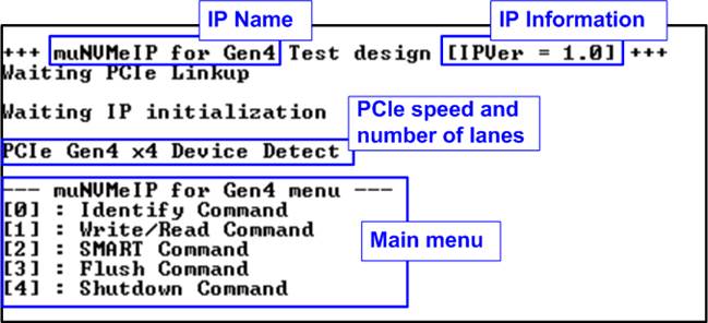
Figure 1‑1 muNVMe-IP for Gen4 main menu
On welcome screen, IP name and IP version number are displayed as the default message to show that FPGA configuration is completed. Next, the PCIe speed and number of PCIe lanes are displayed when PCIe connection can be established. Finally, the test menu is displayed on the console. There are five menus to send each command to muNVMe-IP.
Up to four users can send the Write/Read command at the same time to one NVMe Gen4 SSD. Therefore, Write/Read command is the menu that allows the user to set the number of active users for running multiple Write/Read commands. Other commands (Identify, SMART, Flush, and Shutdown) in this demo can be requested by one user (User#0) without sending Write/Read command request on other users for simple demo. According to the muNVMe-IP specification, the muNVMe-IP can support to run Write/Read command on other users (User#1-#3) while User#0 runs Identify, SMART, or Flush command. More details of each Test menu are shown in the next topic.
2 Test Menu
2.1 Identify Command
Select Ĺ0ĺ to send Identify command to NVMe SSD via User#0 I/F.
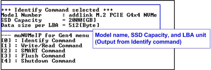
Figure 2‑1 Test result when running Identify command
After finishing the operation, the SSD information output from Identify command is displayed. The console shows three values.
1) SSD model number : This value is decoded from Identify controller data.
2) SSD capacity : This value is signal output from muNVMe-IP.
3) Data size per LBA : This value is signal output from muNVMe-IP. Two values are supported - 512 bytes and 4 Kbytes.
2.2 Write/Read Command
Select Ĺ1ĺ to send Write/Read command by using 1 - 4 users to NVMe SSD. Each user can be set to send Write command, Read command, or no operation. Also, the maximum data rate for Write/Read command of each user interface can be set individually. Therefore, this system can be applied to check the operation in the real system that connects to the several data sources which have different transfer data rate and connects to the monitoring system which reads the data at slow speed for monitoring.
2.2.1 Write command
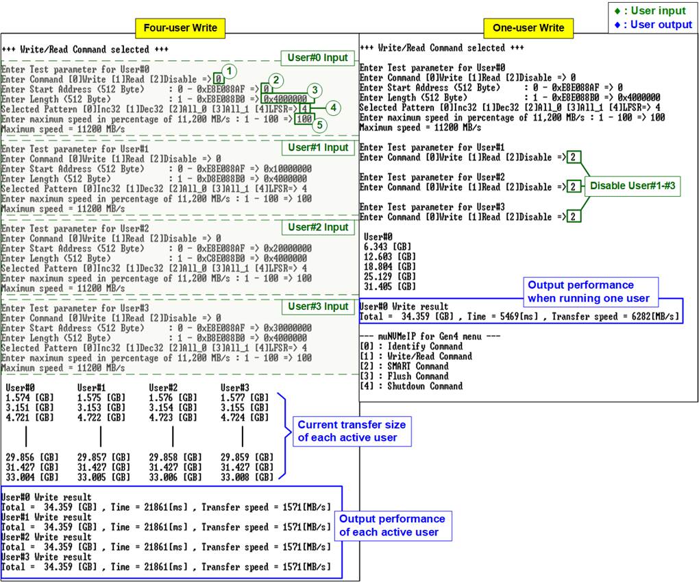
Figure 2‑2 Write command by 4-user and 1-user at maximum speed
As shown in Figure 2‑2, the user sets five inputs for operating Write command which describe in more details as follows.
1) Command: Select command - Write, Read, or Disable (no operation).
2) Start Address: Input start address to write SSD as 512-byte unit. The input is decimal unit when user inputs only digit number. User can add ô0xö to be prefix for hexadecimal unit. When LBA unit of SSD is 4 Kbyte, this input must be aligned to 8.
3) Transfer Length: Input total transfer size as 512-byte unit. The input is decimal unit when user inputs only digit number. User can add ô0xö to be prefix for hexadecimal unit. When LBA unit of SSD is 4 Kbyte, this input must be aligned to 8.
4) Test pattern: Select test data pattern for writing to SSD. There are five patterns, i.e., 32-bit incremental, 32-bit decremental, all 0, all 1, and 32-bit LFSR counter.
5) Maximum Speed: Setting maximum speed in percentage unit of 11,200 MB/s. Valid from 1 to 100.
Note: 11,200 MB/s is calculated by user clock frequency (350 MHz) x data width (256-bit).
When all inputs are valid, the operation begins. While the command is operating, current amount of write data in each active user is displayed on the console every second to show that the system is still alive. Finally, total size, total time usage, and test speed of each active user are displayed on the console after the operation is done.
Figure 2‑2 shows the result when running Write command by four-user and one-user. Total performance of four-user (1571 x 4 = 6284 MB/s) and one-user (6282 MB/s) are almost similar.
The example when limiting the maximum speed of some users is shown in Figure 2‑3. While User#0 is still set to 100% to check the best Write performance, other users (User#1 ľ User#3) set the maximum speed to 5% or 560 MB/s.
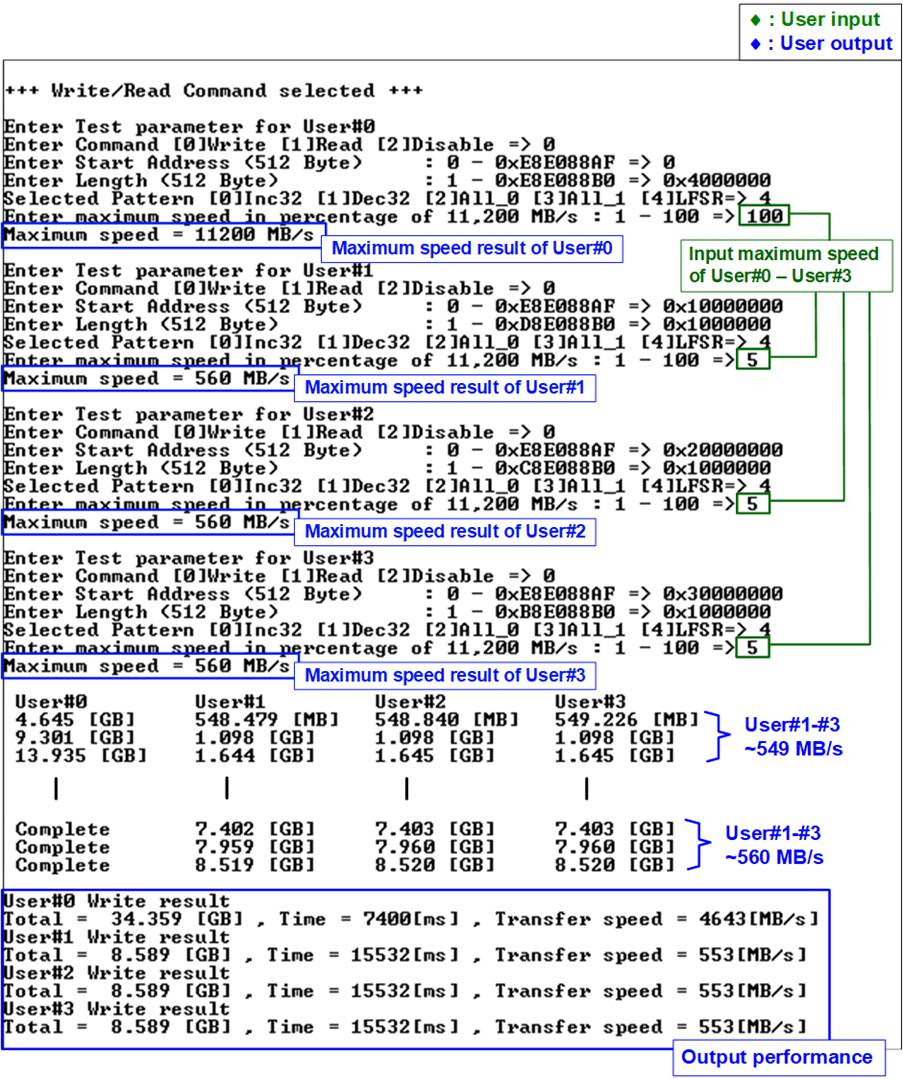
Figure 2‑3 Write command by 4-user with limited maximum speed
The result of Figure 2‑3 shows the high performance on User#0, comparing to other users (User#1-#3). From the previous result that maximum Write performance of this SSD is about 6280 MB/s. Therefore, it is expected that the performance of User#0 should be limited to 6280 ľ (560x3) = 4600 MB/s which is almost matched to the real result.
In this example, transfer length of User#0 is equal to four times of other users, so the operation of User#0 completes before the operation of the remaining users (Run time of User#0=7.4 secs while other users= 15.5 secs). Also, the performance of User#1-#3 when User#0 has no operation is increased (from 549 MB/s to 553 MB/s).
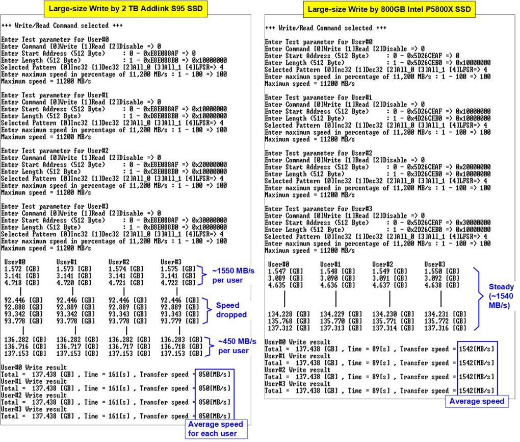
Figure 2‑4 Write performance when using large transfer size
Most SSDs have a cache to show the very high performance for Write command. However, when the transfer size is large until the cache is full, the performance will drop. Figure 2‑4 shows the Write performance result by using two different SSDs. The left-side SSD shows higher performance at the beginning time of the test. After writing the data to SSD for a while, the performance is reduced from 1550 MB/s per user to 450 MB/s per user. The test result shows the average speed of each user. Comparing to the right-side SSD, the performance at the beginning time is less than the left-side SSD but its value is stable at 1540 MB/s until end of transfer. Therefore, the user should check the SSD characteristic to match with the system requirement.
Note: Some SSDs show slower write performance after writing big size data to SSD. The performance is recovered by running Write zero command, Format command, or Sanitized command which is the customized feature. Please contact our sales for more information.
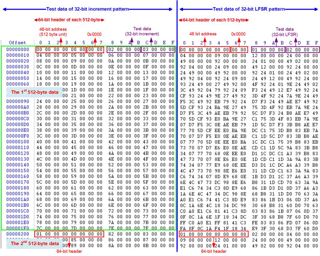
Figure 2‑5 Example Test data of the 1st and 2nd 512-byte by using incremental/LFSR pattern
Test data in SSD is split into 512-byte unit. For incremental, decremental, and LFSR pattern, each 512-byte data has unique 64-bit header consisting of 48-bit address (in 512-byte unit) and 16-bit zero value. The data after 64-bit header is the test pattern which is selected by user.
The left window of Figure 2‑5 shows the example when using 32-bit incremental pattern while the right window shows the example when using 32-bit LFSR pattern. The unique header is not included when running all-0 or all-1 pattern.
When user runs Write/Read command with 4-Kbyte LBA SSD, there is the message displayed on the console to show the input limitation which must be aligned to 8, as shown in Figure 2‑6. When the input does not align to 8, ôInvalid inputö is displayed and the operation is cancelled.
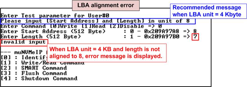
Figure 2‑6 Error message when the input is unaligned for SSD with 4KB LBA unit
Also, Figure 2‑7 shows the example when the input is out of the recommended range for each parameter. The console displays ôInvalid inputö and then the operation is cancelled.
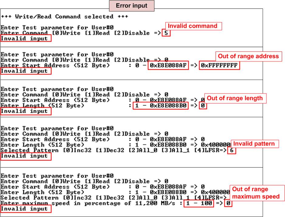
Figure 2‑7 Error message from the invalid input
2.2.2 Read Command
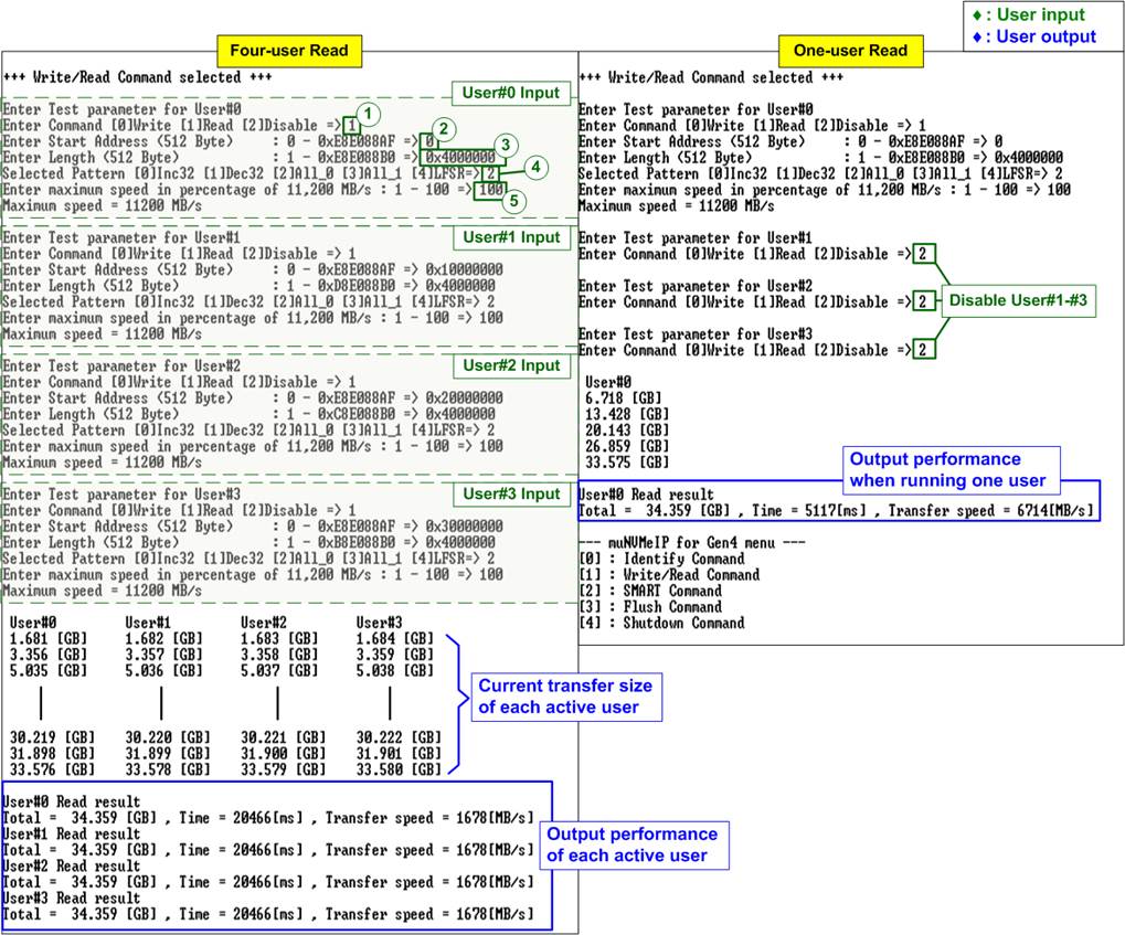
Figure 2‑8 Read command by 4-user and 1-user when using All-zero pattern at maximum speed
For running Read command, the user sets four parameters per user, described as follows.
1) Command: Select command - Write, Read, or Disable (no operation).
2) Start Address: Input start address to read SSD as 512-byte unit. The input is decimal unit when user inputs only digit number. User can add ô0xö to be a prefix for hexadecimal unit. When LBA unit of SSD is 4 Kbyte, this input must be aligned to 8.
3) Transfer Length: Input total transfer size as 512-byte unit. The input is decimal unit when user inputs only digit number. User can add ô0xö to be a prefix for hexadecimal unit. When LBA unit of SSD is 4 Kbyte, this input must be aligned to 8.
4) Test pattern: Select test data pattern to verify data from SSD. Test pattern must be matched with the pattern using in Write Command menu. There are five patterns, i.e., 32-bit incremental, 32-bit decremental, all-0, all-1, and 32-bit LFSR counter.
5) Maximum Speed: Setting maximum speed in percentage unit of 11,200 MB/s. Valid from 1 to 100.
Similar to Write command menu, test system reads data from SSD when all inputs are valid. While running Read command, current amount of read data is displayed on the console every second to show that the system is still alive. Finally, total size, total time usage, and test speed of the active user are displayed on the console after the operation is done.
As shown in Figure 2‑8, total read performance of four-user (1678 x 4 = 6712 MB/s) and one-user (6714 MB/s) are similar. ôInvalid inputö is displayed when some inputs are invalid or unaligned to 8 (when connecting to 4-KB LBA SSD).
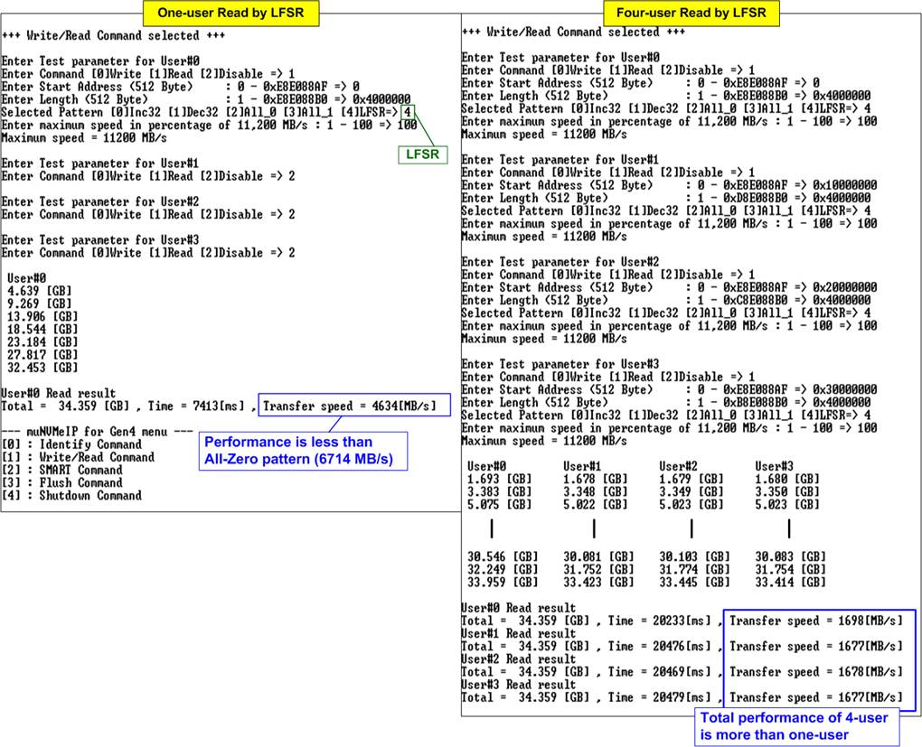
Figure 2‑9 Read command when using LFSR by one-user and four-user
Some SSDs shows the different performance when changing test pattern or adjusting the number of active users. As shown in Figure 2‑9, the performance of one-user is reduced when changing the test pattern from All-zero to LFSR pattern. Comparing to All-zero pattern, the read performance is reduced from 6714 MB/s to 4618 MB/s. However, when the number of active users is increased from 1 to 4, total read performance is increased from 4618 MB/s to 6730 MB/s (1698 + 1677 + 1678 + 1677 MB/s).
Figure 2‑10 shows error message when data verification is failed. ôVerify fail in User#0-#3ö is displayed with the information of the 1st failure data, i.e., the error byte address, the expected value, and the read value.
User can press any key(s) to cancel the read operation. Otherwise, the operation is still run until finishing Read command and then the output performance is displayed on the console. When cancelling the operation, the Read command still runs as the background process and may not finish in a good sequence. It is recommended to power-off/on FPGA board and adapter board that connects with SSD (if connected).
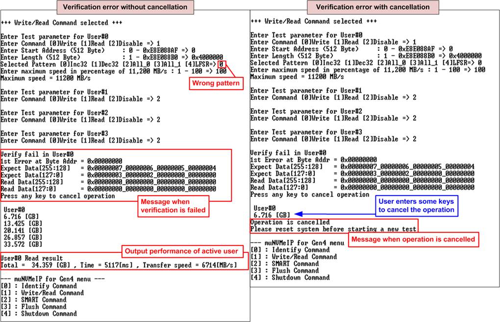
Figure 2‑10 Data verification is failed
2.2.3 Mixed Write/Read command
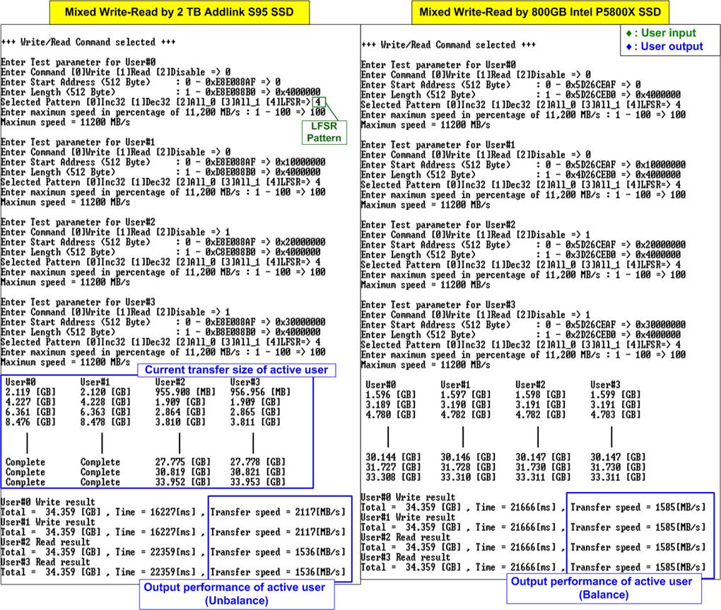
Figure 2‑11 Mixed Write-Read command by using two different SSDs at maximum speed
As shown in Figure 2‑11, the user sets five inputs for operating Write command and Read command which describe in more details as follows.
1) Command: Select command - Write, Read, or Disable (no operation).
2) Start Address: Input start address to write/read SSD as 512-byte unit. The input is decimal unit when user inputs only digit number. User can add ô0xö to be a prefix for hexadecimal unit. When LBA unit of SSD is 4 Kbyte, this input must be aligned to 8.
3) Transfer Length: Input total transfer size as 512-byte unit. The input is decimal unit when user inputs only digit number. User can add ô0xö to be a prefix for hexadecimal unit. When LBA unit of SSD is 4 Kbyte, this input must be aligned to 8.
4) Test pattern: Select test data pattern for writing/verifying data to/from SSD. There are five patterns, i.e., 32-bit incremental, 32-bit decremental, all 0, all 1, and 32-bit LFSR counter.
5) Maximum Speed: Setting maximum speed in percentage unit of 11,200 MB/s. Valid from 1 to 100.
When all inputs are valid, the operation begins. While the command is operating, current amount of write/read data of the active user is displayed on the console every second to show that the system is still alive. Finally, total size, total time usage, and test speed of the active user are displayed on the console after the operation is done. The error message is displayed if the input is invalid or data verification is failed in Read command.
As shown in Figure 2‑11, when mixed Write-Read command are sent to the SSD, the result depends on SSD characteristic. Some SSDs complete Write and Read command at the same time (the right-side SSD) while some SSDs complete Write command before Read command (the left-side SSD).
Figure 2‑12 shows the example result by using two users (one for Write command and another for Read command) to run at maximum speed and limited speed. When running at maximum speed as shown in the left side, the unbalance performance for Write-Read command is displayed. Write performance is about five times of Read performance. There are many applications that use Read command for system monitoring at very low speed while operating Write command at the fastest speed to record the data. Therefore, the right side of Figure 2‑12 is the example to check the maximum Write speed that can be achieved while the slow-speed Read command is operated at the same time.
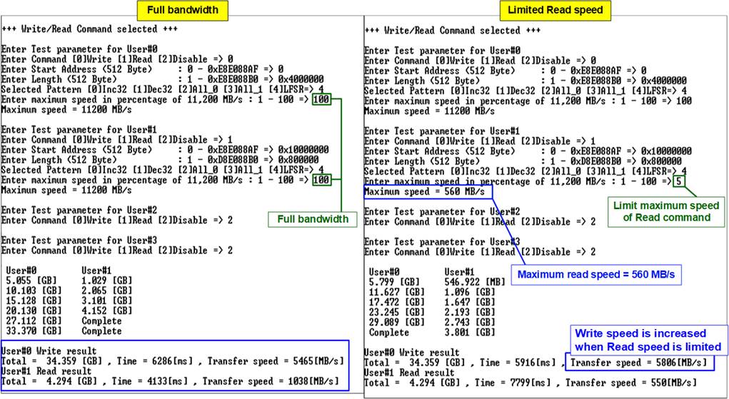
Figure 2‑12 Mixed Write-Read command with limited maximum Read speed
2.3 SMART Command
Select Ĺ2ĺ to send SMART command to NVMe SSD via User#0 I/F.
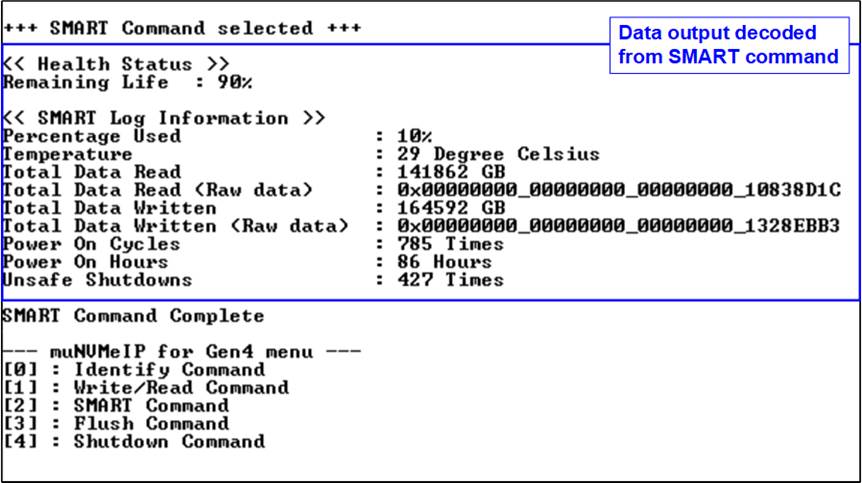
Figure 2‑13 Test result when running SMART command
After finishing the operation, SMART/Health Information (output from SMART command) is displayed as shown in Figure 2‑13. The console shows Health status and SMART log information. Health status shows the remaining life of the SSD in percentage which is calculated from Percentage Used in the SMART log information.
The SMART log information shows seven parameters as follow.
1) Percentage used: Display SSD usage in percentage.
2) Temperature in °C unit.
3) Total Data Read decoded as GB/TB unit. Also, raw data without decoding is displayed by 32 digits of hex number (128 bits). The unit size of raw data is 512,000 bytes.
4) Total Data Written decoded as GB/TB unit. Also, raw data without decoding is displayed by 32 digits of hex number (128 bits). The unit size of raw data is 512,000 bytes.
5) Power On Cycles: Display the number of power cycles.
6) Power On Hours: Display the period of time in hours to show how long the SSD has been powered on.
7) Unsafe Shutdowns: Display the number of unsafe shutdowns of SSD.
2.4 Flush Command
Select Ĺ3ĺ to send Flush command to NVMe SSD via User#0 I/F.
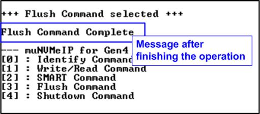
Figure 2‑14 Test result when running Flush command
ôFlush Command Completeö is displayed after finishing Flush operation.
2.5 Shutdown Command
Select Ĺ4ĺ to send Shutdown command to NVMe SSD via User#0 I/F.
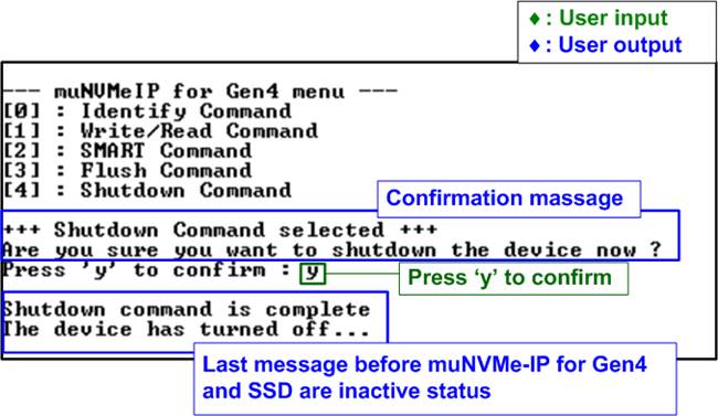
Figure 2‑15 Test result when running Shutdown command
The confirmation message is displayed on the console. User enters Ĺyĺ or ĹYĺ to continue the operation or enters other keys to cancel the operation.
After finishing Shutdown operation, ôShutdown command is completeö is displayed on the console as the last message. Main menu is not displayed anymore. User needs to power off/on test system to start new test operation.
3 Revision History
|
Revision |
Date |
Description |
|
1.1 |
6-Jan-23 |
Add maximum speed limitation feature |
|
1.0 |
4-Oct-22 |
Initial version release |