muNVMe-IP for Gen4 Demo Instruction
Rev1.0 8-Aug-23
2.2.3 Mixed Write/Read command
1 Overview
This document provides instructions for running the muNVMe-IP for Gen4 demo on an FPGA development board. Prior to executing the test, please refer to the ôdg_nvmeip_fpgasetupö document for setting the test environment. Once the demo configuration file has been downloaded to the FPGA, a welcome message will be displayed, as shown in Figure 1‑1.
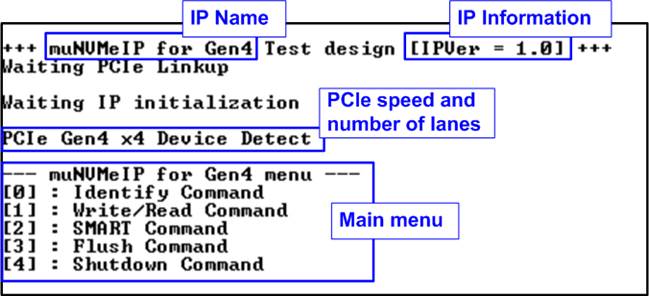
Figure 1‑1 muNVMe-IP for Gen4 main menu
The welcome screen presents the default message, which includes the IP name and version number, confirming the successful completion of FPGA configuration. Subsequently, when a PCIe connection is established, the screen will show the PCIe speed and the number of PCIe lanes. Finally, the console will display the test menu. The menu offers five options for sending various commands to the muNVMe-IP.
The Write/Read command menu allows up to four users to simultaneously send Write/Read commands to an NVMe Gen4 SSD. This menu enables users to specify the number of active users for executing multiple Write/Read commands. The other commands (Identify, SMART, Flush, and Shutdown) can be requested by as single user (User#0) without sending Write/Read command requests to the other users. Further details about each test menu will be covered in the following topic.
2 Test Menu
2.1 Identify Command
To send the Identify command to NVMe SSD via User#0 I/F, select option Ĺ0ĺ.
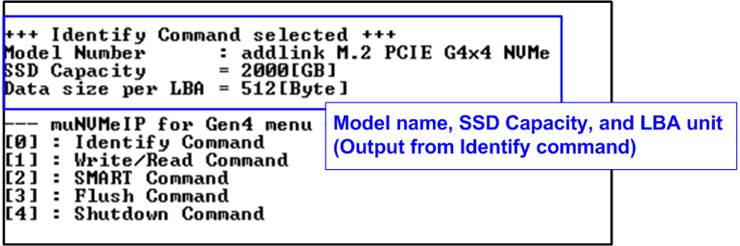
Figure 2‑1 Test result when running Identify command
Once the operation is complete, the console will display the output of the Identify command, which includes three values.
1) SSD model number : This value is obtained by decoding the Identify controller data.
2) SSD capacity : This value is the signal output from the muNVMe-IP.
3) Data size per LBA : This value is the signal output from the muNVMe-IP. It can have two values - 512 bytes and 4 Kbytes.
2.2 Write/Read Command
To send the Write/Read command, select option Ĺ1ĺ and specify the desired number of users ranging from one to four. Each user can be set to perform a Write command, a Read command, or no operation. Additionally, the maximum data rate for each user interface to Write/Read command can be individually set. This system is designed to enable testing in real-world scenarios where multiple data sources with varying transfer rates are connected, along with a monitoring system that reads data at a slower speed for monitoring purposes.
2.2.1 Write command
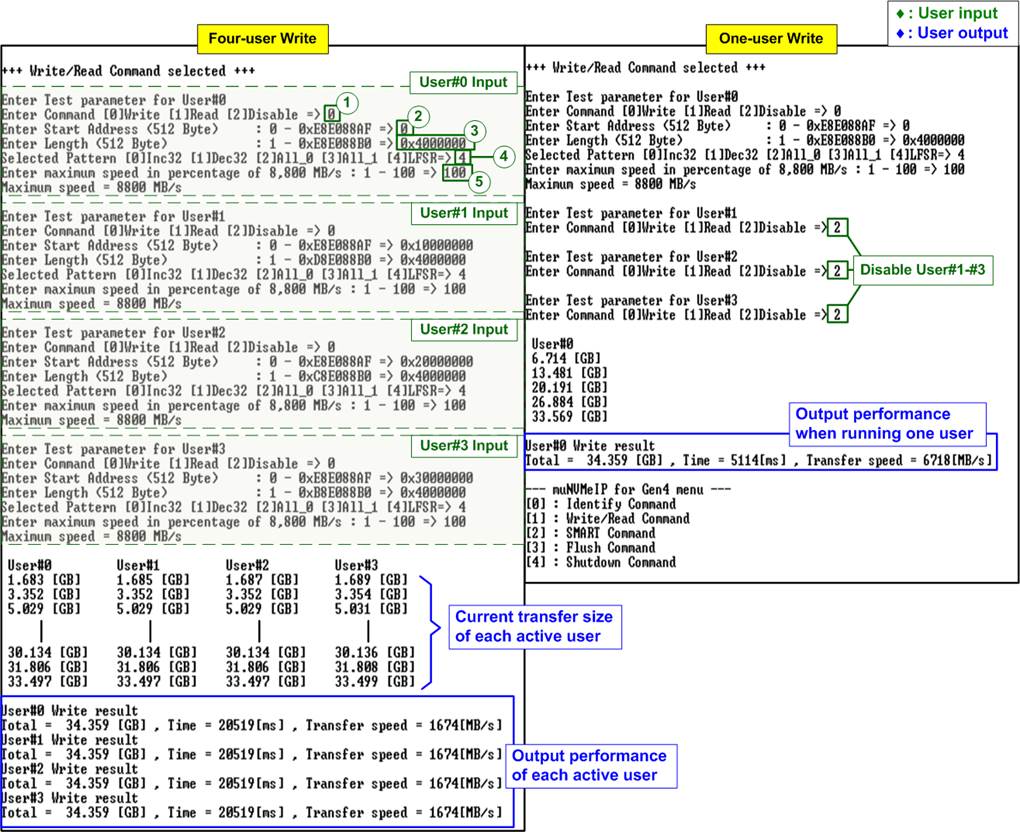
Figure 2‑2 Write command by 4-user and 1-user at maximum speed
As shown in Figure 2‑2, the user must specify the five inputs for operating the Write command, which are described in detail as follows.
1) Command: Select the command type - Write, Read, or Disable (no operation).
2) Start Address: Specify the start address to write the SSD as a 512-byte unit. The input is in decimal unit when the user inputs only digits. The user can add ô0xö as a prefix for hexadecimal units. When the LBA unit of SSD is 4 Kbyte, this input must be aligned to 8.
3) Transfer Length: Specify the total transfer size as a 512-byte unit. The input is in decimal unit when the user inputs only digits. The user can add ô0xö as a prefix for hexadecimal units. When the LBA unit of SSD is 4 Kbyte, this input must be aligned to 8.
4) Test pattern: Used to select the test data pattern for writing to the SSD. The user can choose from five patterns, including 32-bit incremental, 32-bit decremental, all 0, all 1, and 32-bit LFSR counter.
5) Maximum Speed: Set the maximum speed as a percentage of 8,800 MB/s. Valid values range from 1 to 100.
Note: 8,800 MB/s is calculated by multiplying the user clock frequency (275 MHz) by the data width (256-bit).
Once all the inputs are valid, the operation begins. During the command execution, the console will display the current amount of write data for each active user every second to indicate that the system is still running. Upon completion of the operation, the console will display the total size, total time usage, and test speed of each active user.
Figure 2‑2 demonstrates the results obtained when running the Write command with four users and a single user. The total performance achieved by the four users (1674 x 4 = 6696 MB/s) and the single user (6718 MB/s) are nearly identical.
Figure 2‑3 illustrates an example where the maximum speed is limited for some users. While User#0 is set to 100% to assess the best Write performance, other users (User#1 ľ User#3) have their maximum speed set to 5% or 440 MB/s.
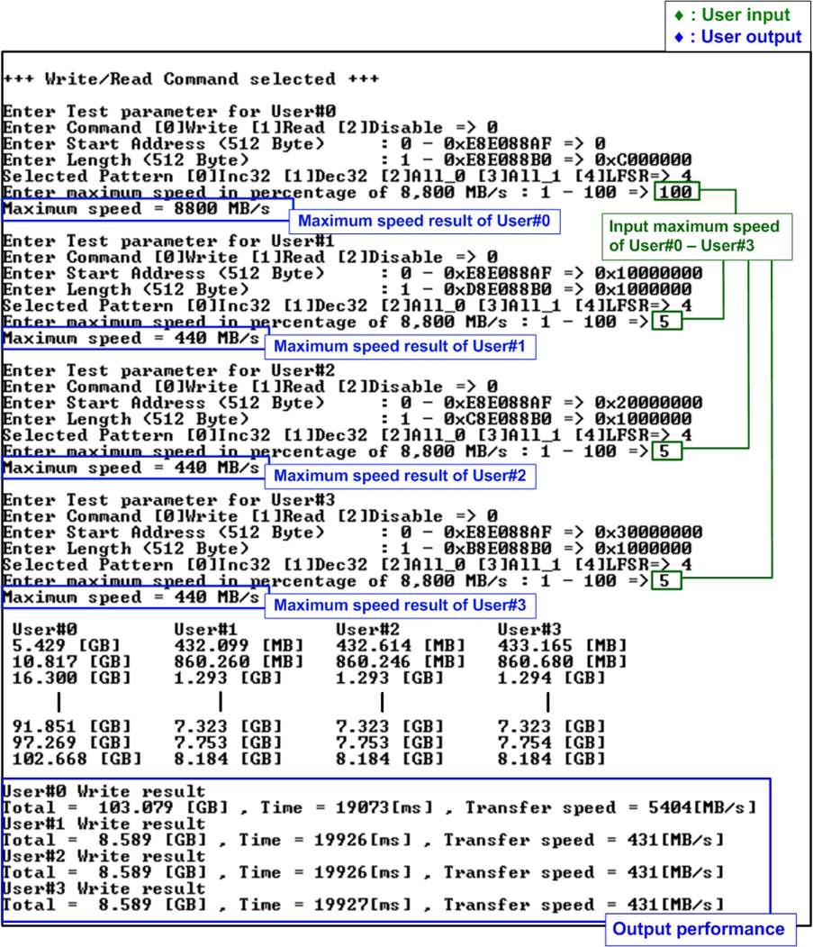
Figure 2‑3 Write command by 4-user with limited maximum speed
The result in Figure 2‑3 shows the higher performance of User#0 compared to the other users (User#1-#3). Considering the previous result indicating a maximum Write performance of approximately 6718 MB/s for the SSD, it is expected that User#0ĺs performance should be limited to 6718 ľ (440x3) = 5398 MB/s, which closely matches the actual result.
Since User#0ĺs expected write performance (5398 MB/s) is around twelve times the write speed of the other users (440 MB/s), the transfer size of User#0 is set to be twelve times that of the other users. This ensures that the write operation of all channels is completed simultaneously. As a result, the speed of each user remains relatively constant throughout the entire duration of the operation.
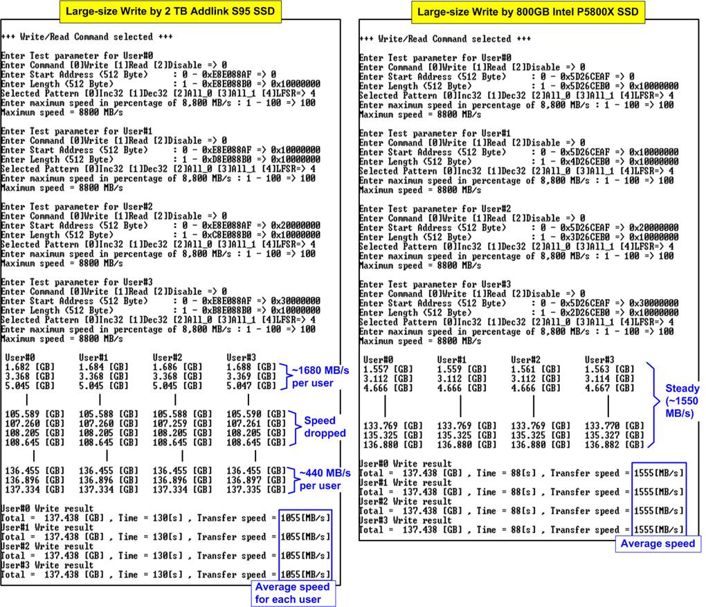
Figure 2‑4 Write performance when using large transfer size
Most SSDs employ a cache mechanism to showcase impressive performance during Write command. However, when the transfer size surpasses the cache capacity, the performance can significantly decline. Figure 2‑4 shows the Write performance results obtained using two different SSDs. On the left side, the SSD initially exhibits higher performance, achieving 1680 MB/s per user. However, as data is written to the SSD over time, the performance decreases to 440 MB/s per user. The test result represents the average speed of each user. Conversely, the right-side SSD exhibits lower initial performance compared to the left-side SSD. However, it maintains a stable speed of 1550 MB/s per user throughput the entire transfer. Therefore, it is crucial for users to assess the characteristics of the SSD and ensure they align with the system requirements.
Note: Some SSDs may exhibit slower write performance after writing a large amount of data. In such cases, performance can be restored by executing commands such as Write zero, Format, or Sanitized, which are customized features. For more information, please contact our sales team.
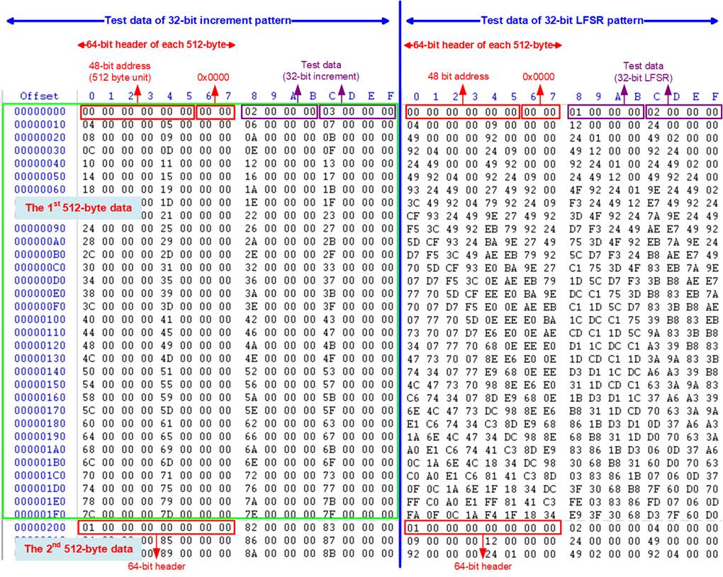
Figure 2‑5 Example Test data of the 1st and 2nd 512-byte by using incremental/LFSR pattern
Test data in the SSD is divided into 512-byte units. For incremental, decremental, and LFSR patterns, each 512-byte data has a unique 64-bit header that consists of a 48-bit address (in 512-byte units) and a 16-bit zero value. The data following the 64-bit header is the test pattern selected by the user.
The left window of Figure 2‑5 shows an example when using a 32-bit incremental pattern while the right window shows an example when using a 32-bit LFSR pattern. The unique header is not included when running an all-0 or all-1 pattern.
When a user runs the Write or Read command with a 4-Kbyte LBA SSD, a message is displayed on the console to show the input limitation, which must be aligned to 8, as shown in Figure 2‑6. If the input is not aligned to 8, the console displays ôInvalid inputö, and the operation is cancelled.
Figure 2‑7 shows an example when the input is out of the recommended range for each parameter. The console displays ôInvalid inputö, and then the operation is cancelled.
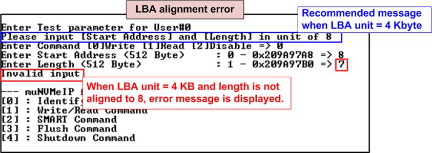
Figure 2‑6 Error message when the input is unaligned for SSD with 4KB LBA unit
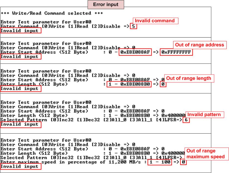
Figure 2‑7 Error message from the invalid input
2.2.2 Read Command
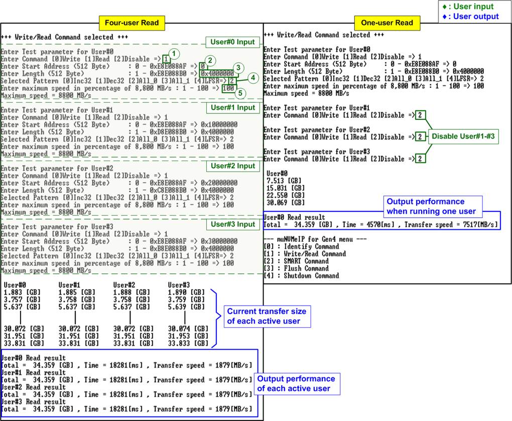
Figure 2‑8 Read command by 4-user and 1-user when using All-zero pattern at maximum speed
For operating the Read command, the user must specify the five inputs, which are described in detail as follows.
1) Command: Select the command type - Write, Read, or Disable (no operation).
2) Start Address: Specify the start address to read the SSD as a 512-byte unit. The input is in decimal unit when the user inputs only digits. The user can add ô0xö as a prefix for hexadecimal units. When the LBA unit of SSD is 4 Kbyte, this input must be aligned to 8.
3) Transfer Length: Specify the total transfer size as a 512-byte unit. The input is in decimal unit when the user inputs only digits. The user can add ô0xö as a prefix for hexadecimal units. When the LBA unit of SSD is 4 Kbyte, this input must be aligned to 8.
4) Test pattern: Used to select the test data pattern for reading and verifying data from the SSD. The test pattern must match the one used in the Write command menu. There are five available patterns: 32-bit incremental, 32-bit decremental, all 0, all 1, and 32-bit LFSR counter.
5) Maximum Speed: Set the maximum speed as a percentage of 8,800 MB/s. Valid values range from 1 to 100.
When valid inputs are provided, the test system reads data from the SSD. During the execution of the Read command, the console displays the current amount of read data every second to indicate that the system is still running. Upon completion of the operation, the console will display the total size, total time usage, and test speed of each active user.
Figure 2‑8 shows the comparable total read performance between four users (1879 x 4 = 7516 MB/s) and a single user (7517 MB/s). However, in cases where inputs are invalid or not aligned to 8 (in relation to 4-KB LBA SSD connection), an ôInvalid inputö message is displayed.
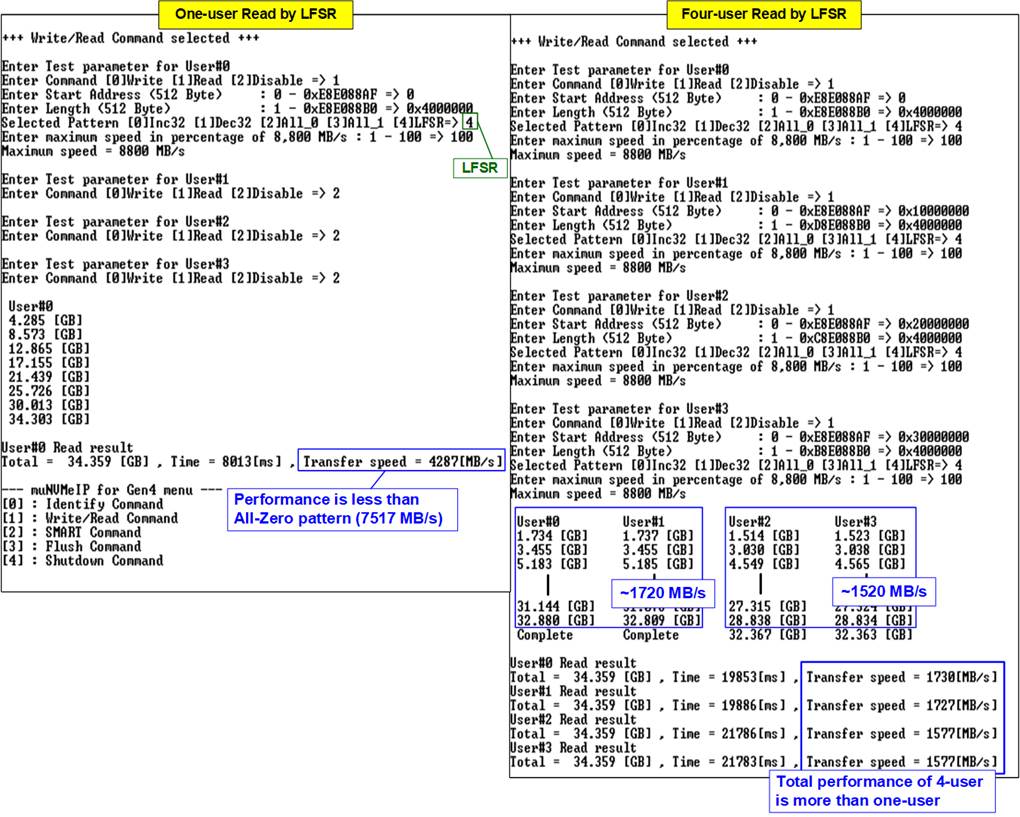
Figure 2‑9 Read command when using LFSR by one-user and four-user
Some SSDs may exhibit varying or unbalanced performance when changing test patterns or adjusting the number of active users. In Figure 2‑9, the performance of a single user decreases when transitioning from the All-zero pattern to the LFSR pattern, resulting in a drop from 7517 MB/s to 4287 MB/s. When utilizing four users, the SSD demonstrates unbalanced performance across User#0 to User#3. However, increasing the number of active users from 1 to 4 leads to an overall improvement in total read performance, increasing from 4287 MB/s to 6611 MB/s (1730 + 1727 + 1577 + 1577 MB/s).
In case of a failed data verification during Read command, an error message is displayed on the console, as shown in Figure 2‑10. The message ôVerify fail in User#0-#3ö is displayed with information about the first failure data, such as the error byte address, the expected value, and the read value.
To cancel the Read operation, the user can press any key(s). However, if the operation is not cancelled, it will continue running until it finishes. Once it has finished, the output performance is displayed on the console.
Though the operation is cancelled, the Read command continues running as a background process and may not finish in a proper sequence. Therefore, it is recommended to power off and then power on both the FPGA board and adapter board (if connected) after cancelling the operation.
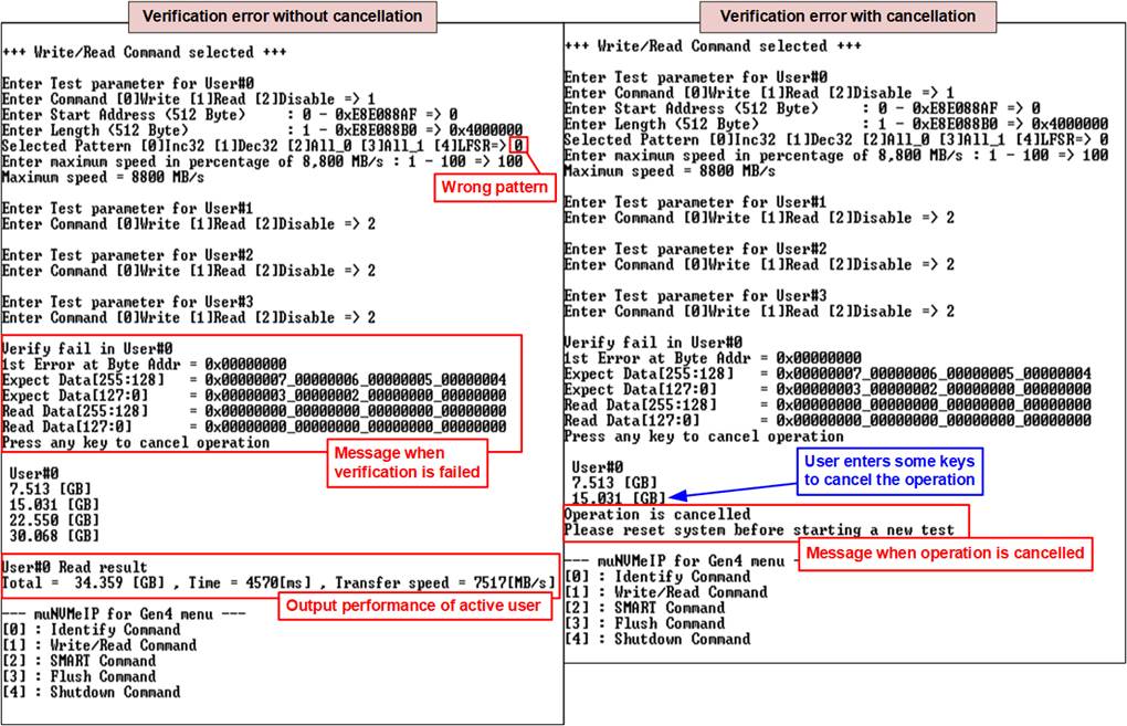
Figure 2‑10 Data verification is failed
2.2.3 Mixed Write/Read command
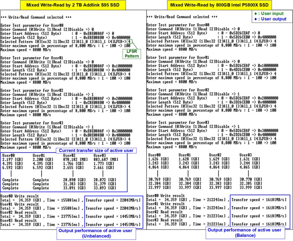
Figure 2‑11 Mixed Write-Read command by using two different SSDs at maximum speed
As shown in Figure 2‑11, the user must specify the five inputs for operating the Write and Read commands, which are described in detail as follows.
1) Command: Select the command type - Write, Read, or Disable (no operation).
2) Start Address: Specify the start address to write/read the SSD as a 512-byte unit. The input is in decimal unit when the user inputs only digits. The user can add ô0xö as a prefix for hexadecimal units. When the LBA unit of SSD is 4 Kbyte, this input must be aligned to 8.
3) Transfer Length: Specify the total transfer size as a 512-byte unit. The input is in decimal unit when the user inputs only digits. The user can add ô0xö as a prefix for hexadecimal units. When the LBA unit of SSD is 4 Kbyte, this input must be aligned to 8.
4) Test pattern: Used to select the test data pattern for writing to the SSD or verifying from the SSD. The user can choose from five patterns, including 32-bit incremental, 32-bit decremental, all 0, all 1, and 32-bit LFSR counter.
5) Maximum Speed: Set the maximum speed as a percentage of 8,800 MB/s. Valid values range from 1 to 100.
Once all the inputs are valid, the operation begins. During the command execution, the console will display the current amount of write data or read data for each active user every second to indicate that the system is still running. Upon completion of the operation, the console will display the total size, total time usage, and test speed of each active user. If an error is found from invalid input or failed data verification, an error message is displayed on the console.
Figure 2‑11 illustrates the behavior of SSDs when receiving mixed Write-Read commands. The result depends on the characteristics of the SSD. Some SSDs can execute Write and Read commands simultaneously (as shown on the right side), while others complete the Write command before the Read command (as shown on the left side).
Figure 2‑12 demonstrates an example result using two users, one for Write command and another for Read command, running at both maximum and limited speeds. On the left side, when running at maximum speed, the performance of Write-Read command is imbalanced, with the Write performance being approximately five times the Read performance. In various applications, Read command is often utilized for system monitoring at very low speed, while Write command is executed at the fastest speed to record data. Therefore, the example on the right side of Figure 2‑12 aims to assess the maximum achievable Write speed while simultaneously operating the Read command at a slower speed.
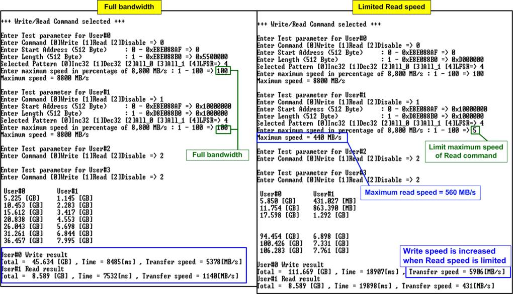
Figure 2‑12 Mixed Write-Read command with limited maximum Read speed
2.3 SMART Command
To send a SMART command to the NVMe SSD via User#0 I/F, select option Ĺ2ĺ. Once the operation is complete, the console will display the SMART/Health Information output, as shown in Figure 2‑13. This information includes both the Health status and SMART log information.
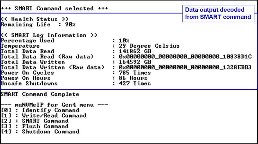
Figure 2‑13 Test result when running SMART command
The Health status displays the remaining life of the SSD as a percentage, which is calculated from the Percentage Used value in the SMART log information. The SMART log information displays the following seven parameters.
1) Percentage used: The percentage of the SSDĺs lifespan that has been consumed.
2) Temperature: The temperature of the SSD in degree Celsius.
3) Total Data Read: The total amount of data that has been read from the SSD, displayed in GB/TB units. Additionally, the raw data without decoding is displayed as a 32-digit hex number (128 bits). The unit size of raw data is 512,000 bytes.
4) Total Data Written: The total amount of data that has been written to the SSD, displayed in GB/TB units. Additionally, the raw data without decoding is displayed as a 32-digit hex number (128 bits). The unit size of raw data is 512,000 bytes.
5) Power On Cycles: The number of times the SSD has been powered on.
6) Power On Hours: The total amount of time in hours that the SSD has been powered on.
7) Unsafe Shutdowns: The number of times the SSD has experienced an unsafe shutdown.
2.4 Flush Command
To initiate a Flush command on the NVMe SSD, select option Ĺ3ĺ from the menu. The Flush command ensures that all modified data in the cache memory is written to Flash memory in the SSD.
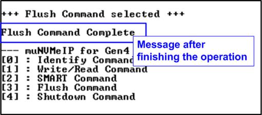
Figure 2‑14 Test result when running Flush command
Once the Flush operation is completed, the consoled will display the message ôFlush Command Completeö.
2.5 Shutdown Command
To send a Shutdown command to the NVMe SSD via User#0 I/F, select option Ĺ4ĺ.
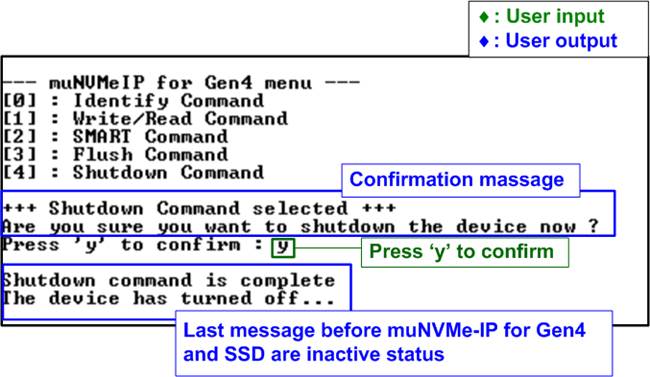
Figure 2‑15 Test result when running Shutdown command
A confirmation message will be displayed on the console, and the user will need to enter Ĺyĺ or ĹYĺ to proceed with the operation. Press any other key to cancel the operation.
Once the Shutdown operation is complete, ôShutdown command is completeö will be displayed as the final message. The console becomes inactive. To begin a new test operation, the user will need to power off and on the test system.
3 Revision History
|
Revision |
Date |
Description |
|
1.0 |
2-Jun-23 |
Initial version release |