4-Ch RAID0 (NVMe-IP for Gen5) Demo Instruction
1 Overview
This document describes the instruction to run 4-ch RAID0 demo using NVMe-IP for Gen5. The demo is run on FPGA development board to access four NVMe Gen5 SSDs in a RAID0 configuration. There are seven test menus for executing each command - Identify, Write, Read, SMART, Flush, Secure Erase, and Shutdown. The user can control the test operations through FPGA console.
Before proceeding with the demo, please ensure that the FPGA board has been completely setup according to the ōdg_nvmeip_fpgasetup_g5_intelö document, which can be found at the following link.
https://dgway.com/products/IP/NVMe-IP/dg_nvmeip_fpgasetup_g5_intel_en/
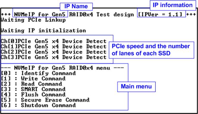
Figure 1‑1 4-Ch NVMe-IP (Gen5) RAID0 demo main menu
On welcome screen, the IP name and version number are displayed. The next message provides the information about the PCIe speed and the number of PCIe lanes of each channel. Finally, the test menu is displayed on the console.
2 Test Menu
2.1 Identify Command
The Identify command is used to retrieve information about the NVMe SSD. To send the Identify command, select æ0Æ from the console menu. Once the command operation is completed, the console displays the following three pieces of information.
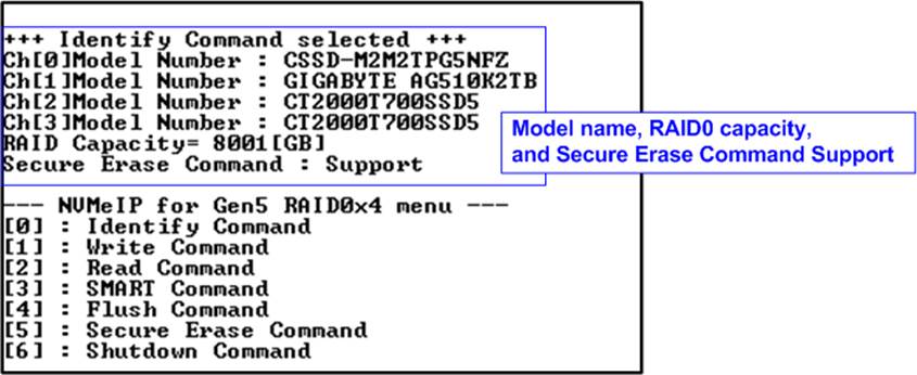
Figure 2‑1 Test result when running Identify command
1) SSD model number : This information is decoded from Identify controller data of each SSD.
2) RAID capacity : This value is determined by multiplying SSD capacity in channel#0 by 4. Therefore, it is recommended to connect four SSDs for RAID0.
Note: If the connected SSDs have different capacities, it is recommended to connect the SSD with the smallest capacity to Ch#0.
3) Secure Erase Command Support: This information is decoded from the Identify controller data, indicating whether the SSD is capable of executing the Secure Erase command.
2.2 Write Command
The Write command is used to write data to the RAID0. To execute the Write command, select æ1Æ from the test menu.
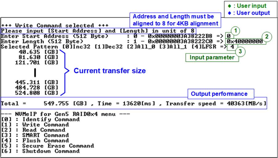
Figure 2‑2 Input and Test result when running Write command
The user needs to input three parameters.
1) Start Address: Specifies the start address to write the RAID0 as a 512-byte unit. The input is in decimal unit when the user inputs only digits. The user can add ō0xö as a prefix for hexadecimal units. The input must be aligned to 8 for 4KB alignment.
2) Transfer Length: Specifies the total transfer size as a 512-byte unit. The input is in decimal unit when the user inputs only digits. The user can add ō0xö as a prefix for hexadecimal units. The input must be aligned to 8 for 4KB alignment.
3) Test pattern: Used to select the test data pattern for writing to the RAID0. The user can choose from five patterns, including 32-bit incremental, 32-bit decremental, all 0, all 1, and 32-bit LFSR counter.
Once all input parameters are validated, the write operation begins. The console displays the current amount of written data every second to indicate that the system is still running. Upon completion, the console shows the total size of data, time usage, and test speed as the test results.
Note:
1. The performance of RAID0x4 is approximately four times that of a single SSD. To achieve optimal performance, it is recommended to use the same SSD model for all SSD channels. However, if different SSD models are used in the system, the RAID0x4 performance is limited to four times of the performance of the slowest SSD.
2. The write performance of SSDs may decrease after long data transfer. In some cases, the performance can be restored by executing the Secure Erase command.
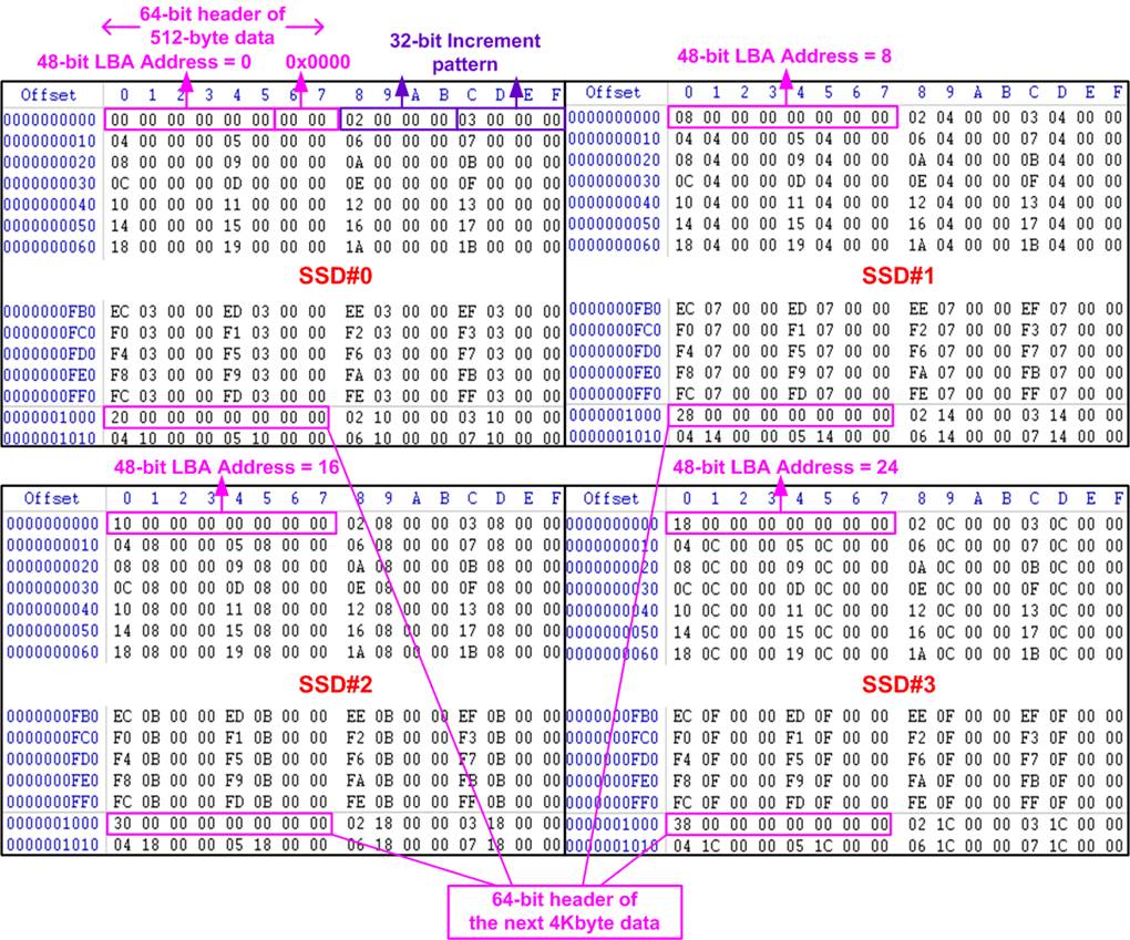
Figure 2‑3 Sample Test data for the 1st 4KB of every SSD using an incremental pattern
In the 4-ch RAID0 demo, the RAID0 stripe size of RAID0 is configured to 4Kbytes. When using incremental, decremental, and LFSR patterns, each 4Kbyte data block has a unique 64-bit header which consists of a 48-bit address (measured in 512-byte units) and a 16-bit zero value. Following the header, the data block contains the user-selected test pattern. However, when using an all-0 or all-1 pattern, the unique 64-bit header is not included.
In the RAID0 configuration, the 1st stripe corresponds to the first 4Kbyte section of SSD#0. The 2nd stripe ¢ the 4th stripe map to the first 4Kbyte sections of SSD#1 ¢ SSD#3, as shown in Figure 2‑3.
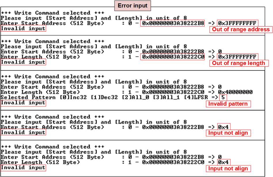
Figure 2‑4 Error message from the invalid input
Figure 2‑4 provides an example when the input is out-of-range from the recommended range for each parameter and is not aligned to 8. In such cases, the console displays ōInvalid inputö, and then the operation is cancelled.
2.3 Read Command
The Read command is used to read data from the RAID0. To execute the Read command, select æ2Æ from the test menu.
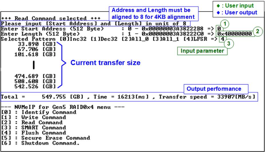
Figure 2‑5 Input and result of Read Command menu
The user needs to input three parameters.
1) Start Address: Specifies the start address to read the RAID0 as a 512-byte unit. The input is in decimal unit when the user inputs only digits. The user can add ō0xö as a prefix for hexadecimal units. The input must be aligned to 8 for 4KB alignment.
2) Transfer Length: Specifies the total transfer size as a 512-byte unit. The input is in decimal unit when the user inputs only digits. The user can add ō0xö as a prefix for hexadecimal units. The input must be aligned to 8 for 4KB alignment.
3) Test pattern: Used to select the test data pattern for reading and verifying data from the RAID0. The test pattern must match the one used in the Write command menu. There are five available patterns: 32-bit incremental, 32-bit decremental, all 0, all 1, and 32-bit LFSR counter.
If all inputs are valid, the test system reads data from the RAID0. While the operation is in progress, the console displays the current amount of read data every second to indicate that the system is still running. When the operation is completed, the console shows the total size of data, time usage, and test speed.
Note:
1. The performance of RAID0x4 is approximately four times that of a single SSD. To achieve optimal performance, it is recommended to use the same SSD model for all SSD channels. However, if different SSD models are used in the system, the RAID0x4 performance is limited to four times of the performance of the slowest SSD.
2. It is found that some SSDs shows varying performance characteristic when different test patterns are utilized. For instance, the read performance is better when using all-zero pattern compared to using an LFSR pattern.
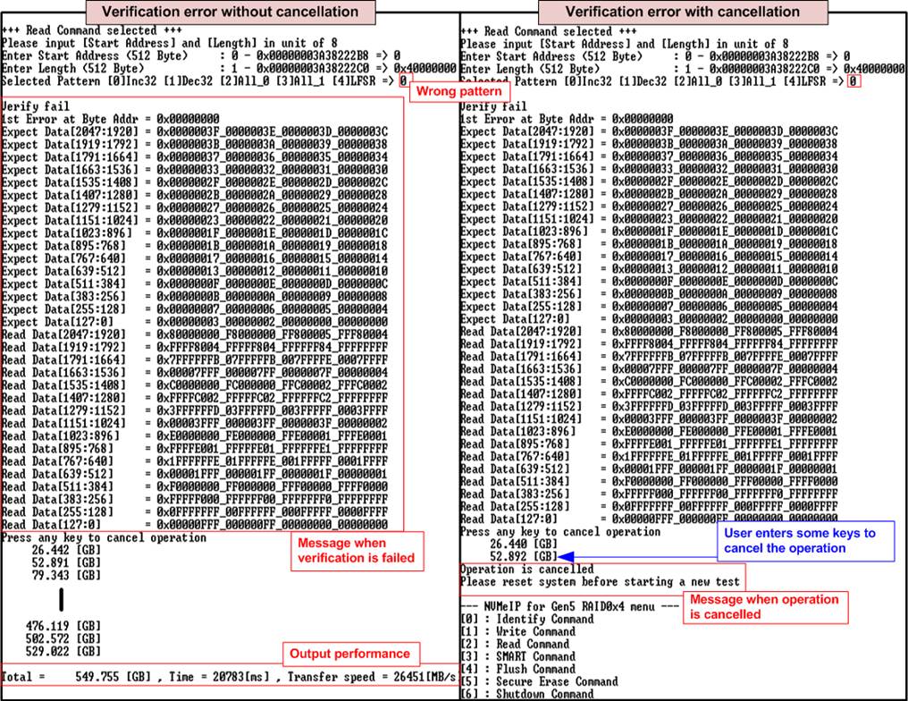
Figure 2‑6 Data verification is failed
In case of a failed data verification during Read command, an error message is displayed on the console, as shown in Figure 2‑6. The message ōVerify failö is displayed with information about the first failure data, such as the error byte address, the expected value, and the read value.
To cancel the Read operation, the user can press any key(s). However, if the operation is not cancelled, it will continue running until it finishes. Once it has finished, the output performance is displayed on the console.
Though the operation is cancelled, the Read command continues running as a background process and may not finish in a proper sequence. Therefore, it is recommended to power off and then power on both the FPGA board and adapter board (if connected) after cancelling the operation.
2.4 SMART Command
Select æ3Æ to send a SMART command to the RAID0. After the operation is complete, the console will display the SMART/Health Information output (see Figure 2‑7). This information includes both the Health status and SMART log information.
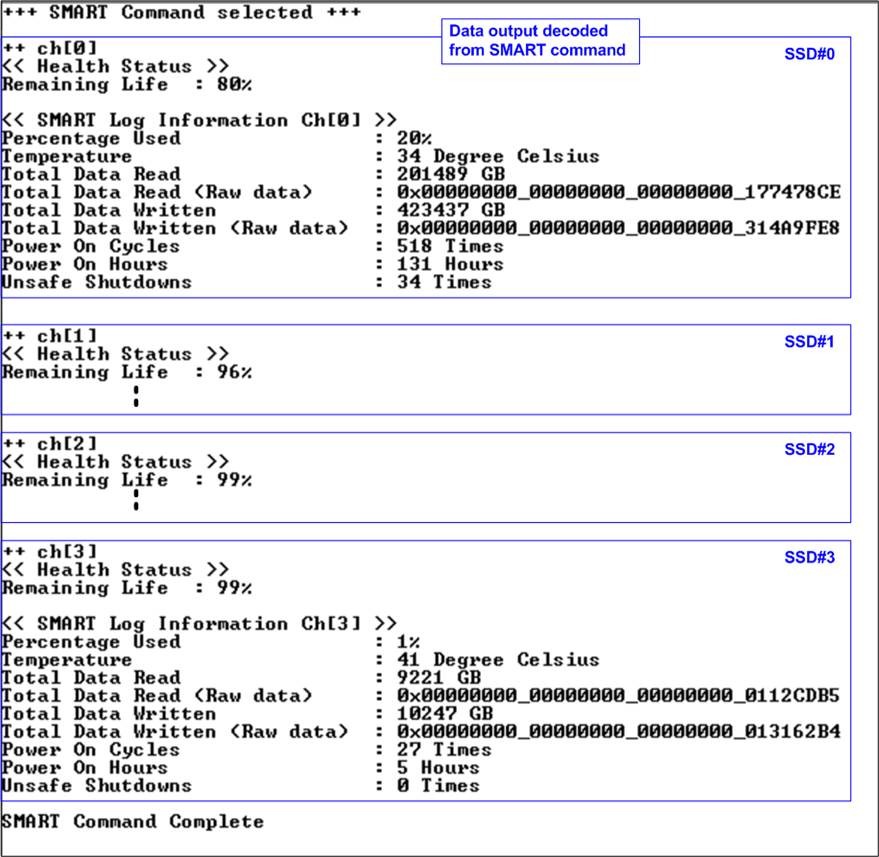
Figure 2‑7 Test result when running SMART command
The Health status displays the remaining life of the SSD as a percentage, which is calculated from the Percentage Used value in the SMART log information. The SMART log information displays the following seven parameters.
1) Percentage used: The percentage of the SSDÆs lifespan that has been consumed.
2) Temperature: The temperature of the SSD in degree Celsius.
3) Total Data Read: The total amount of data that has been read from the SSD, displayed in GB/TB units. Additionally, the raw data without decoding is displayed as a 32-digit hex number (128 bits). The unit size of raw data is 512,000 bytes.
4) Total Data Written: The total amount of data that has been written to the SSD, displayed in GB/TB units. Additionally, the raw data without decoding is displayed as a 32-digit hex number (128 bits). The unit size of raw data is 512,000 bytes.
5) Power On Cycles: The number of times the SSD has been powered on.
6) Power On Hours: The total amount of time in hours that the SSD has been powered on.
7) Unsafe Shutdowns: The number of times the SSD has experienced an unsafe shutdown.
2.5 Flush Command
To initiate a Flush command on the RAID0, select option æ4Æ from the menu. The Flush command ensures that all modified data in the cache memory is written to Flash memory in the SSD.
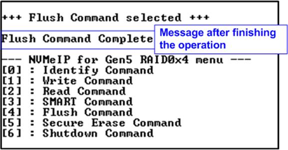
Figure 2‑8 Test result when running Flush command
Once the Flush operation is completed, the consoled will display the message ōFlush Command Completeö.
2.6 Secure Erase Command
Select option æ5Æ to initiate a Secure Erase command to the RAID0. Before the operation starts, a confirmation message is displayed on the console, requesting the user to confirm the command. The user must enter æyÆ or æYÆ to continue with the operation or any other key to cancel.
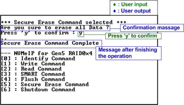
Figure 2‑9 Test result when running Secure Erase command
Once the Secure Erase command is completed, the console displays the message ōSecure Erase Command Completeö.
2.7 Shutdown Command
Select æ6Æ to send the Shutdown command to RAID0.
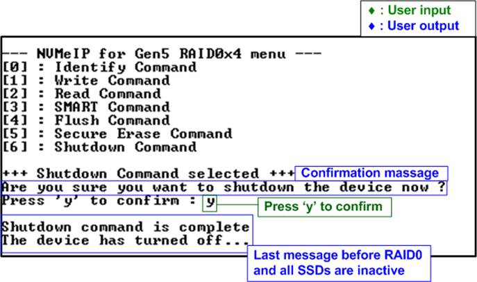
Figure 2‑10 Test result when running in Shutdown command
A confirmation message will be displayed on the console, and the user will need to enter æyÆ or æYÆ to proceed with the operation. Press any other key to cancel the operation.
Once the Shutdown operation is complete, ōShutdown command is completeö will be displayed as the final message. The console becomes inactive. To begin a new test operation, the user will need to power off and on the test system.
3 Revision History
|
Revision |
Date |
Description |
|
1.0 |
2-Oct-23 |
Initial version release |