Demo Instruction for NVMe-IP/NVMeG3-IP
1 Overview
This document provides instructions for running the NVMe-IP/NVMeG3-IP demo on FPGA development boards, which involves accessing an NVMe SSD. The demo supports seven commands: Identify, Write, Read, SMART, Flush, Secure Erase, and Shutdown, and users can control the test operation through the FPGA console.
To get started, user must first follow the �dg_nvmeip_fpgasetup� document to set up the FPGA board. Once the board is setup, the welcome screen is displayed, which shows the IP name, IP version number, PCIe speed, and number of PCIe lanes after the IP finishes initialization. The test menu is then displayed on the console, and users can select the desired test operation by setting the input on the console.
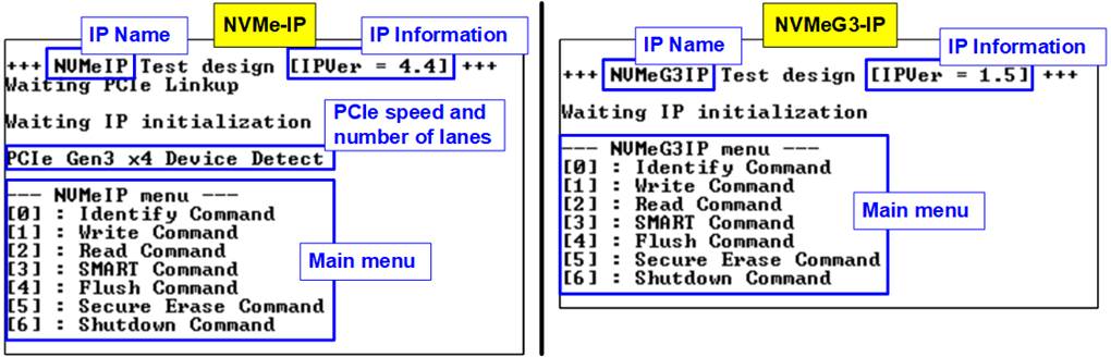
Figure 1‑1 NVMe-IP main menu
2 Test Menu
2.1 Identify Command
The Identify command is used to retrieve information about the NVMe SSD. To send the Identify command, select �0� from the console menu. Once the command operation is completed, the console displays the following four pieces of information.
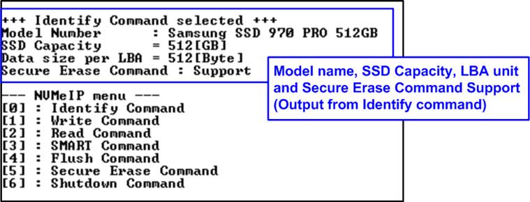
Figure 2‑1 Test result when running Identify command
1) SSD model number : This value is decoded from Identify controller data.
2) SSD capacity : This value is signal output from NVMe-IP.
3) Data size per LBA : This value is signal output from NVMe-IP. Two values are supported 512 byte and 4 KB.
4) Secure Erase Command Support: This value is decoded from the Identify controller data to show whether the SSD supports the Secure Erase command.
2.2 Write Command
The Write command is used to write data to the NVMe SSD. To execute the Write command, select �1� from the test menu.
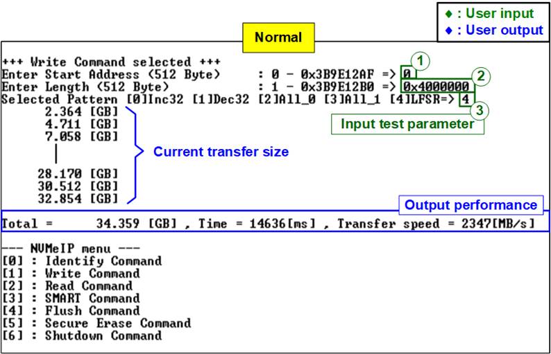
Figure 2‑2 Test result when running Write command
The user needs to input three parameters.
1) Start Address: Specifies the start address to write the SSD as a 512-byte unit. The input is in decimal unit when the user inputs only digits. The user can add �0x� as a prefix for hexadecimal units. When the LBA unit of SSD is 4 KB, this input must align 8.
2) Transfer Length: Specifies the total transfer size as a 512-byte unit. The input is in decimal unit when the user inputs only digits. The user can add �0x� as a prefix for hexadecimal units. When the LBA unit of SSD is 4 KB, this input must align 8.
3) Test pattern: Used to select the test data pattern for writing to the SSD. The user can choose from five patterns, including 32-bit incremental, 32-bit decremental, all 0, all 1, and 32-bit LFSR counter.
Once all input parameters are validated, the write operation begins. The console displays the current amount of written data every second to indicate that the system is still running. Upon completion, the console shows the total size of data, time usage, and test speed as the test results.
Note: The write performance of SSDs may decrease after long data transfer. In some cases, the performance can be restored by executing the Secure Erase command
Our experiments reveal that using an NVMe Gen4 SSD with an NVMe-IP (Gen3) core can enhance write performance. Figure 2‑3 demonstrates this improvment, showing a write performance of approximately 3000 MB/s.
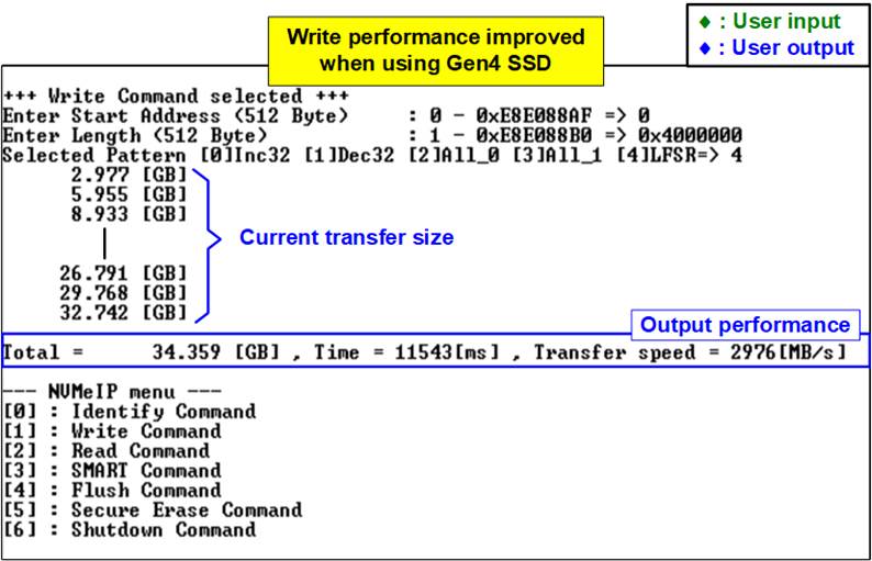
Figure 2‑3 Test result when running Write command with NVMe Gen4 SSD at Gen3 speed
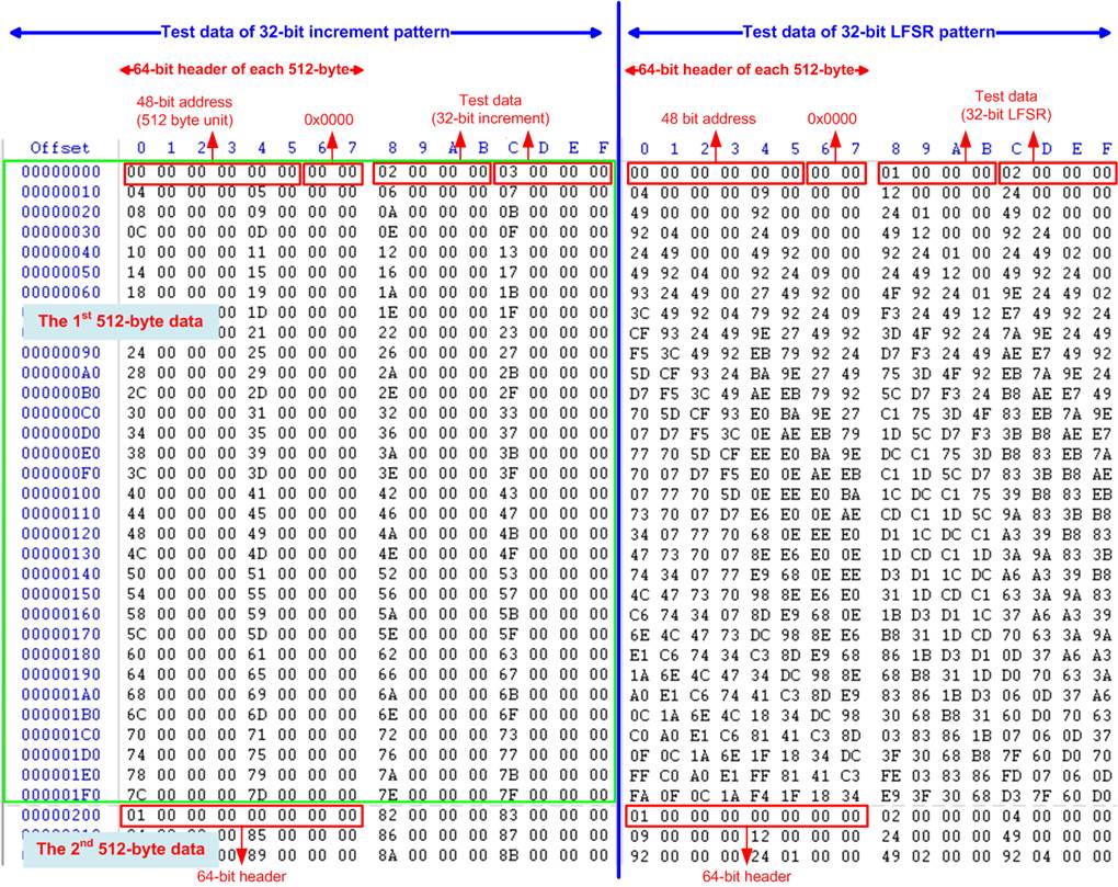
Figure 2‑4 Example Test data of the 1st and 2nd 512-byte by using incremental/LFSR pattern
Test data in the SSD is divided into 512-byte units. For incremental, decremental, and LFSR patterns, each 512-byte data has a unique 64-bit header that consists of a 48-bit address (in 512-byte units) and a 16-bit zero value. The data following the 64-bit header is the test pattern selected by the user.
The left window of Figure 2‑4 shows an example when using a 32-bit incremental pattern while the right window shows an example when using a 32-bit LFSR pattern. The unique header is not included when running all-0 or all-1 pattern.
When users run the Write or Read command with a 4KB LBA SSD, a message is displayed on the console to show the input limitation, which must be aligned to 8, as shown in Figure 2‑5. When the input does not align to 8, the console displays �Invalid input�, and the operation is cancelled.
Figure 2‑6 shows an example when the input is out of the recommended range for each parameter. The console displays �Invalid input�, and then the operation is cancelled.
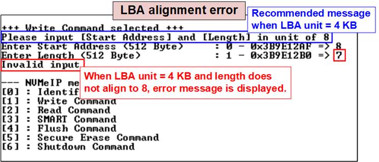
Figure 2‑5 Error message when the input does not unalign for SSD with 4KB LBA unit
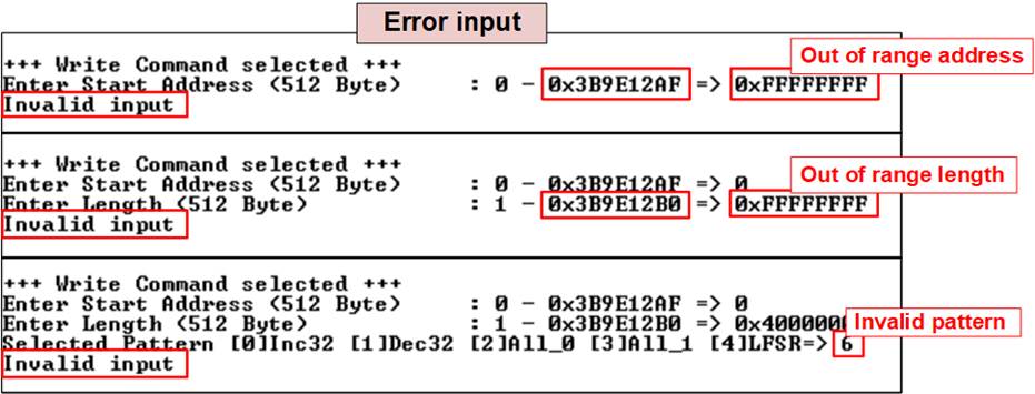
Figure 2‑6 Error message from the invalid input
2.3 Read Command
The Read command is used to read data to the NVMe SSD. To execute the Read command, select �2� from the test menu.
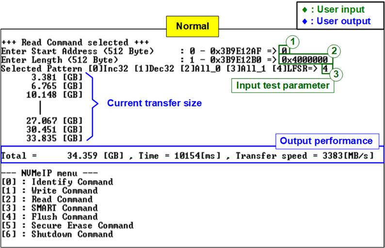
Figure 2‑7 Test result when running Read command
The user needs to input three parameters.
1) Start Address: Specifies the start address to read the SSD as a 512-byte unit. The input is in decimal unit when the user inputs only digits. The user can add �0x� as a prefix for hexadecimal units. When the LBA unit of SSD is 4 KB, this input must align 8.
2) Transfer Length: Specifies the total transfer size as a 512-byte unit. The input is in decimal unit when the user inputs only digits. The user can add �0x� as a prefix for hexadecimal units. When the LBA unit of SSD is 4 KB, this input must align 8.
3) Test pattern: Used to select the test data pattern for reading and verifying data from the SSD. The test pattern must match the one used in the Write command menu. There are five available patterns: 32-bit incremental, 32-bit decremental, all 0, all 1, and 32-bit LFSR counter.
If all inputs are valid, the test system reads data from the SSD. While the operation is in progress, the console displays the current amount of read data every second to indicate that the system is still running. When the operation is completed, the console shows the total size of data, time usage, and test speed.
If any of the inputs are invalid or 8-byte unalignment (for 4KB LBA SSDs), the console displays the message �Invalid input� and cancels the operation.
In case of a failed data verification during Read command, an error message is displayed on the console, as shown in Figure 2‑8. The message �Verify fail� is displayed with information about the first failure data, such as the error byte address, the expected value, and the read value.
To cancel the Read operation, the user can press any key(s). However, if the operation is not cancelled, it will continue running until it finishes. Once it has finished, the output performance is displayed on the console.
Though the operation is cancelled, the Read command continues running as a background process and may not finish in a proper sequence. Therefore, it is recommended to power off and then power on both the FPGA board and adapter board (if connected) after cancelling the operation.

Figure 2‑8 Data verification is failed
2.4 SMART Command
Select �3� to send a SMART command to the NVMe SSD. After the operation is completed, the console will display the SMART/Health Information output (see Figure 2‑9). This information includes both the Health status and SMART log information.
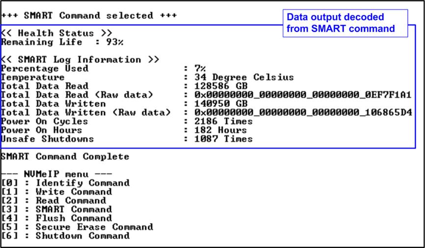
Figure 2‑9 Test result when running SMART command
The Health status displays the remaining life of the SSD as a percentage, which is calculated from the Percentage Used value in the SMART log information. The SMART log information displays the following seven parameters.
1) Percentage used: The percentage of the SSD�s lifespan that has been consumed.
2) Temperature: The temperature of the SSD in degree Celsius.
3) Total Data Read: The total amount of data that has been read from the SSD, displayed in GB/TB units. Additionally, the raw data without decoding is displayed as a 32-digit hex number (128 bits). The unit size of raw data is 512,000 bytes.
4) Total Data Written: The total amount of data that has been written to the SSD, displayed in GB/TB units. Additionally, the raw data without decoding is displayed as a 32-digit hex number (128 bits). The unit size of raw data is 512,000 bytes.
5) Power On Cycles: The number of times the SSD has been powered on.
6) Power On Hours: The total amount of time in hours that the SSD has been powered on.
7) Unsafe Shutdowns: The number of times the SSD has experienced an unsafe shutdown.
2.5 Flush Command
To initiate a Flush command on the NVMe SSD, select option �4� from the menu. The Flush command ensures that all modified data in the cache memory is written to Flash memory in the SSD.
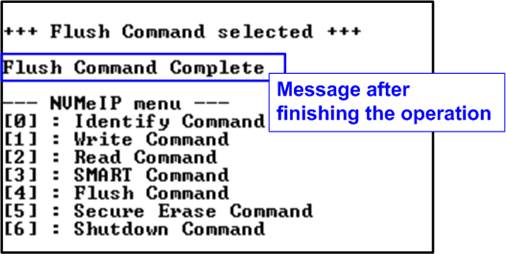
Figure 2‑10 Test result when running Flush command
Once the Flush operation is completed, the consoled will display the message �Flush Command Complete�.
2.6 Secure Erase Command
Select option �5� to initiate a Secure Erase command to the NVMe SSD. Before the operation starts, a confirmation message is displayed on the console, requesting the user to confirm the command. The user must enter �y� or �Y� to continue with the operation or any other key to cancel.
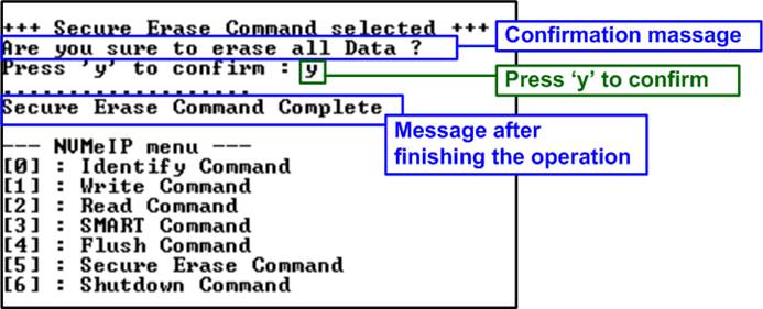
Figure 2‑11 Test result when running Secure Erase command
Once the Secure Erase command is completed, the consoled displays the message �Secure Erase Command Complete�.
2.7 Shutdown Command
Select �6� to send Shutdown command to NVMe SSD.
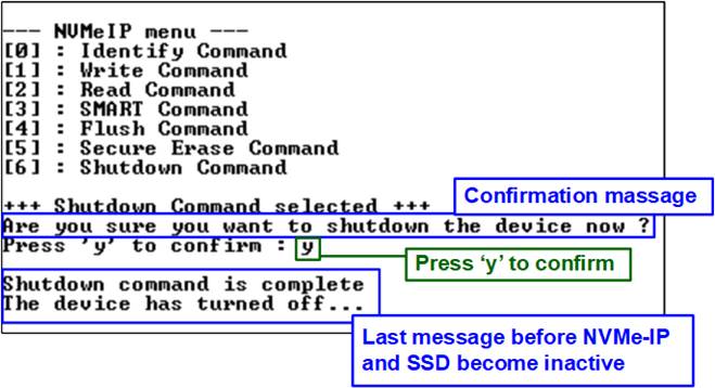
Figure 2‑12 Shutdown command with confirmation
A confirmation message will be displayed on the console, and the user will need to enter �y� or �Y� to proceed with the operation. Press any other key to cancel the operation.
Once the Shutdown operation is completed, �Shutdown command is complete� will be displayed as the final message. The console becomes inactive. To begin a new test operation, the user will need to power off and on the test system.
3 Revision History
|
Revision |
Date |
Description |
|
4.4 |
12-Dec-23 |
Add Secure Erase Command |
|
4.3 |
4-Jun-21 |
Include NVMeG3IP |
|
4.2 |
19-Mar-21 |
Update SMART log information |
|
4.1 |
27-Aug-20 |
Update the information when data verification is failed |
|
4.0 |
29-Jun-20 |
Remove FPGA setup from the document |
|
1.0 |
2-Jun-16 |
Initial version release |