NVMe-IP for Gen4 Demo Instruction
Rev2.0 15-Aug-23
1 Overview
This document describes the instruction to run NVMe-IP for Gen4 demo on FPGA development board. One NVMe SSD is accessed for running the demo. There are six commands that can run, i.e., Identify, Write, Read, SMART, Flush, and Shutdown command. User controls test operation via FPGA console.
After user finishes FPGA board setup following “dg_nvmeip_fpgasetup” document, the welcome screen is displayed.
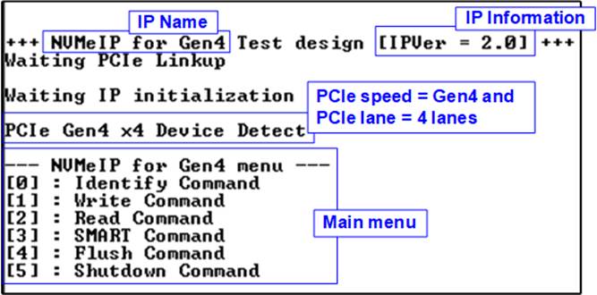
Figure 1‑1 NVMe-IP for Gen4 main menu
On welcome screen, IP name and IP version number are displayed. The PCIe speed and number of PCIe lanes are displayed after IP finishing initialization. Finally, the test menu is displayed on the console. The user sets the input on the console for selecting test operation.
2 Test Menu
2.1 Identify Command
Select ‘0’ to send Identify command to NVMe SSD.
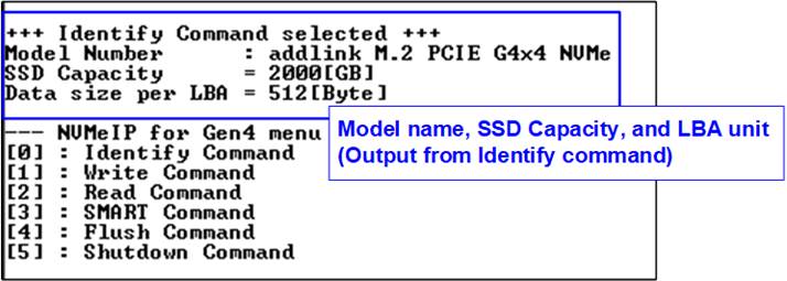
Figure 2‑1 Test result when running Identify command
After finishing the operation, the SSD information output from Identify command is displayed. The console shows three values.
1) SSD model number : This value is decoded from Identify controller data.
2) SSD capacity : This value is signal output from NVMe-IP.
3) Data size per LBA : This value is signal output from NVMe-IP. Two values are supported - 512 bytes and 4 Kbytes.
2.2 Write Command
Select ‘1’ to send Write command to NVMe SSD.
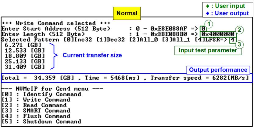
Figure 2‑2 Input and Test result when running Write command
User inputs three parameters as follows.
1) Start Address: Input start address to write SSD as 512-byte unit. The input is decimal unit when user inputs only digit number. User can add “0x” to be a prefix for hexadecimal unit. When LBA unit of SSD is 4 Kbyte, this input must be aligned to 8.
2) Transfer Length: Input total transfer size as 512-byte unit. The input is decimal unit when user inputs only digit number. User can add “0x” to be a prefix for hexadecimal unit. When LBA unit of SSD is 4 Kbyte, this input must be aligned to 8.
3) Test pattern: Select test data pattern for writing to SSD. There are five patterns, i.e., 32-bit incremental, 32-bit decremental, all 0, all 1, and 32-bit LFSR counter.
When all inputs are valid, the operation begins. While writing data, current amount of Write data is displayed on the console every second to show that system is still alive. Finally, total size, total time usage, and test speed are displayed on the console as a test result.
Note: Some SSDs show slower write performance after writing large size data to SSD. The write performance can be recovered after running Write zero command, Format command, or Sanitized command which is the customized design. Please contact our sales for more information.
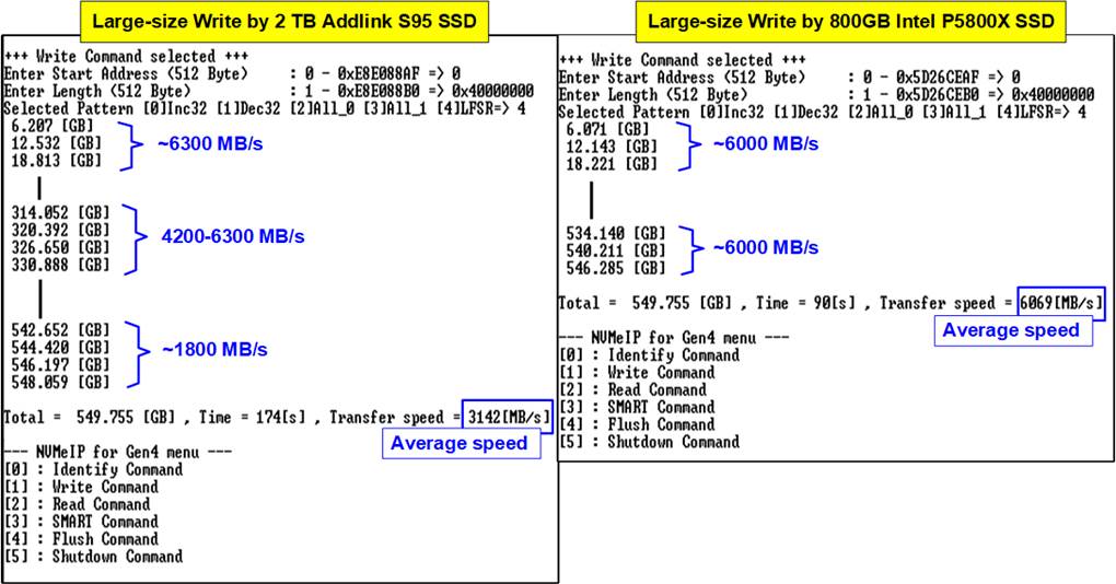
Figure 2‑3 Write performance when using large transfer size
Most SSDs have a cache to show the very high performance for Write command. However, when the transfer size is large until the cache is full, the performance will drop. Figure 2‑3 shows the Write performance result by using two different SSDs. The first SSD on the left side shows higher performance after starting the test. After transferring 320 MB data, the performance is reduced. The result shows the average speed. Comparing to the second SSD on the right side, the performance on the initial time is less than the first SSD but the performance is very stable. Therefore, the user should select the SSD that has the characteristic fit to the system requirement.
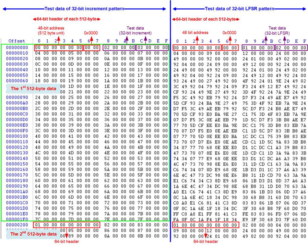
Figure 2‑4 Example Test data of the 1st and 2nd 512-byte by using incremental/LFSR pattern
Test data in SSD is split into 512-byte unit. For incremental, decremental, and LFSR pattern, each 512-byte data has unique 64-bit header consisting of 48-bit address (in 512-byte unit) and 16-bit zero value. The data after 64-bit header is the test pattern which is selected by user.
The left window of Figure 2‑4 shows the example when using 32-bit incremental pattern while the right window shows the example when using 32-bit LFSR pattern. The unique header is not included when running all-0 or all-1 pattern.
When user runs Write or Read command with 4-Kbyte LBA SSD, there is the message displayed on the console to show the input limitation which must be aligned to 8, as shown in Figure 2‑5. When the input does not align to 8, “Invalid input” is displayed and the operation is cancelled.
Figure 2‑6 shows the example when the input is out of the recommended range for each parameter. The console displays “Invalid input” and then the operation is cancelled.
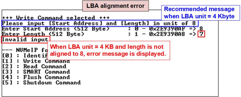
Figure 2‑5 Error message when the input is unaligned for SSD with 4KB LBA unit
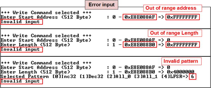
Figure 2‑6 Error message from the invalid input
2.3 Read Command
Select ‘2’ to send Read command to NVMe SSD.
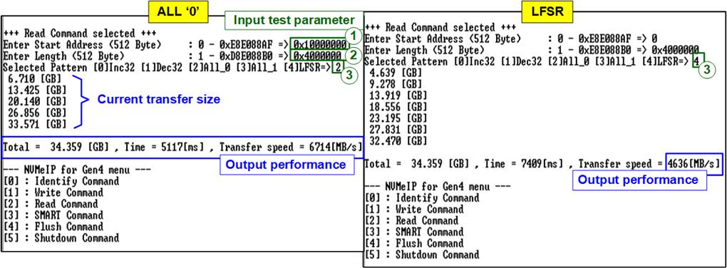
Figure 2‑7 Input and Test result when running Read command
User inputs three parameters as follows.
1) Start Address: Input start address to read SSD as 512-byte unit. The input is decimal unit when user inputs only digit number. User can add “0x” to be a prefix for hexadecimal unit. When LBA unit of SSD is 4 Kbyte, this input must be aligned to 8.
2) Transfer Length: Input total transfer size as 512-byte unit. The input is decimal unit when user inputs only digit number. User can add “0x” to be a prefix for hexadecimal unit. When LBA unit of SSD is 4 Kbyte, this input must be aligned to 8.
3) Test pattern: Select test data pattern to verify data from SSD. Test pattern must be matched with the pattern using in Write Command menu. There are five patterns, i.e., 32-bit incremental, 32-bit decremental, all-0, all-1, and 32-bit LFSR counter
Similar to Write command menu, test system reads data from SSD when all inputs are valid. While reading data, current amount of read data is displayed on the console every second to show that system is still alive. Total size, total time usage, and test speed are displayed after finishing the operation.
“Invalid input” is displayed when some inputs are invalid or unaligned to 8 (when connecting to 4-KB LBA SSD).
Note: Some SSDs shows the different performance when changing test pattern. As shown in Figure 2‑7, the best read performance is achieved by using all-zero pattern. While the performance is reduced when using LFSR pattern.
Some SSDs which have stable characteristic such as 800GB Intel P5800X, the performance does not depend on the test pattern. As shown in Figure 2‑8, the performance when using LFST pattern is still high.
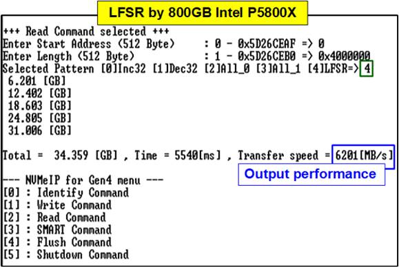
Figure 2‑8 Test result when running Read command by another SSD
Figure 2‑9 shows error message when data verification is failed. “Verify fail” is displayed with the information of the 1st failure data, i.e., the error byte address, the expected value, and the read value.
User can press any key(s) to cancel read operation. Otherwise, the operation is still run until finishing Read command. After that, the output performance is displayed on the console.
When cancelling the operation, the Read command still runs as the background process and may not finish in a good sequence. It is recommended to power-off/on FPGA board and adapter board (if connected).
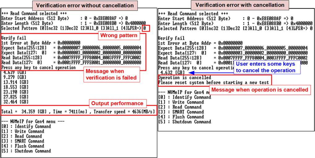
Figure 2‑9 Data verification is failed
2.4 SMART Command
Select ‘3’ to send SMART command to NVMe SSD.
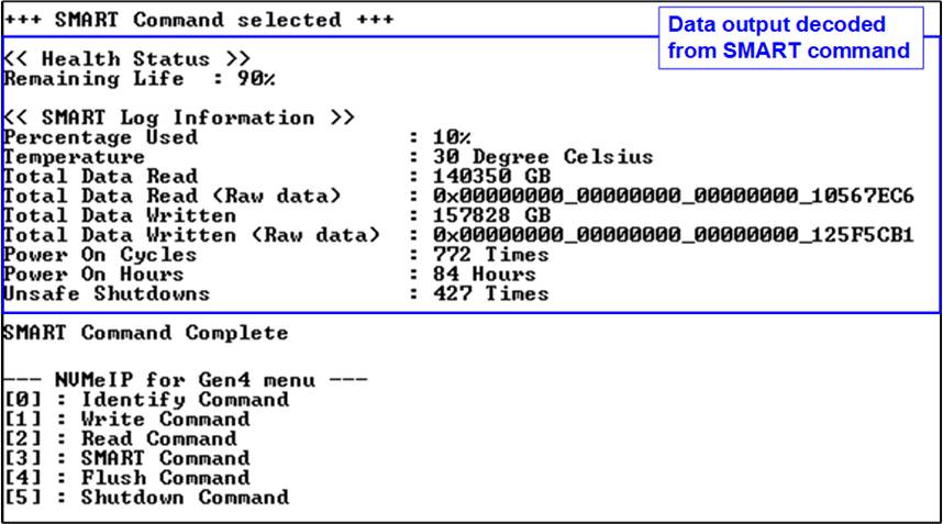
Figure 2‑10 Test result when running SMART command
After finishing the operation, SMART/Health Information (output from SMART command) is displayed as shown in Figure 2‑10. The console shows Health status and SMART log information. Health status shows the remaining life of the SSD in percent unit which is calculated from Percentage Used in the SMART log information.
The SMART log information shows seven parameters as follow.
1) Percentage used: Display SSD usage in percent unit.
2) Temperature in °C unit.
3) Total Data Read decoded as GB/TB unit. Also, raw data without decoding is displayed by 32 digits of hex number (128 bits). The unit size of raw data is 512,000 bytes.
4) Total Data Written decoded as GB/TB unit. Also, raw data without decoding is displayed by 32 digits of hex number (128 bits). The unit size of raw data is 512,000 bytes.
5) Power On Cycles: Display the number of power cycles.
6) Power On Hours: Display the period of time in hours to show how long the SSD has been powered on.
7) Unsafe Shutdowns: Display the number of unsafe shutdowns of SSD
2.5 Flush Command
Select ‘4’ to send Flush command to NVMe SSD.
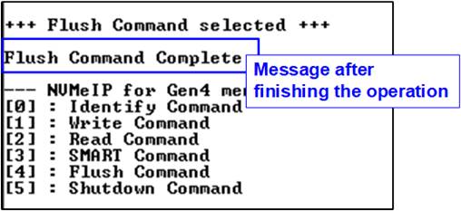
Figure 2‑11 Test result when running Flush command
“Flush Command Complete” is displayed after finishing Flush operation.
2.6 Shutdown Command
Select ‘5’ to send Shutdown command to NVMe SSD.
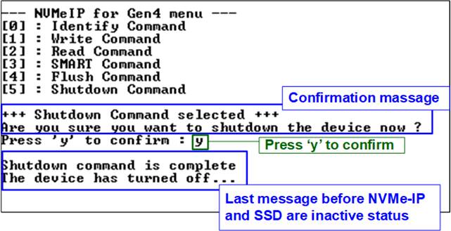
Figure 2‑12 Shutdown command with confirmation
The confirmation message is displayed on the console. User enters ‘y’ or ‘Y’ to continue the operation or enters other keys to cancel the operation.
After finishing Shutdown operation, “Shutdown command is complete” is displayed on the console as the last message. Main menu is not displayed anymore. User needs to power off/on test system to start new test operation.
3 Revision History
|
Revision |
Date |
Description |
|
2.0 |
29-Sep-22 |
Update IP and test result |
|
1.0 |
1-Jun-21 |
Initial version release |