FPGA set up for NVMeTCP10G-IP
1 Introduction
This document provides a comprehensive guide for setting up an FPGA board to demonstrate the NVMeTCP10G-IP. It includes step-by-step instructions for connecting to a target NVMe SSD within a PC via a 10G Ethernet connection, as depicted in Figure 1‑1.
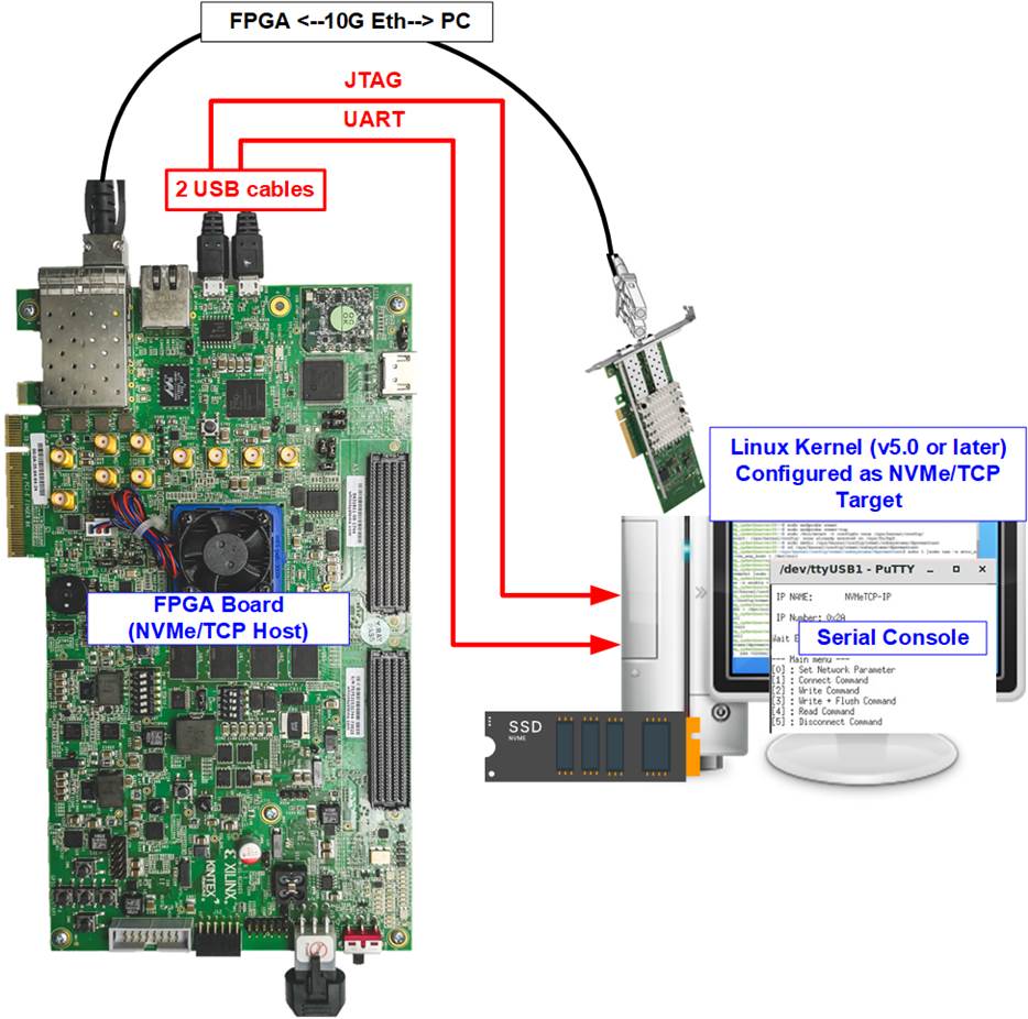
Figure 1‑1 Test environment for the NVMeTCP10G-IP
The host system utilizes an FPGA board integrated with the NVMeTCP10G-IP, facilitating the management and execution of NVMe over TCP commands. The target system consists of a PC equipped with an NVMe SSD and a 10G Ethernet connection. The PC must run a Linux OS with a kernel version of 5.0 or later, which supports the NVMe/TCP driver.
Both the host and the target systems are configured to communicate within the same network domain using a 10G Ethernet connection. For user interactions, the FPGA employs a Serial console interface. In the setup illustrated in Figure 1‑1, a single PC serves dual roles: as the target system for NVMe/TCP operations and as the user interface via the Serial console.
Before initiating the test, ensure that the following hardware components are prepared and configured.
· FPGA development boards: ZCU106, ZCU102, KCU105, or VCK190.
· PC Setup
i) Operating System: Install Linux with a kernel version 5.0 or later.
ii) Storage: Equip the IP with at least one NVMe SSD.
iii) Network: Install a 10G Ethernet card.
· 10G Ethernet cable:
a) Use a 10G SFP+ Active Optical Cable (AOC) or 10G SFP+ transceivers (10G BASE-R) paired with an optical cable (LC to LC, Multimode).
b) For setup involving the VCK190 board, use a QSFP+ to four SFP+ cable.
· USB cables:
a) ZCU106, ZCU102, and KCU105: Two micro USB cables are required for programming the FPGA and establishing the Serial console connection.
b) VCK190: A USB type-C cable is used for programming the FPGA and establishing the Serial console.
· Software
i) Install Serial console software like PuTTY on the PC. Configure the console with the following settings: Baudrate=115,200, Data=8-bit, Non-parity, and Stop=1-bit.
ii) Use the Vivado tool for FPGA programming, installed on the PC.
Note: Additional Hardware References:
1) 10G Network Adapter: Intel Ethernet Converged Network Adapter X710-DA2
2) Ethernet Cable Options:
a) 10-Gigabit SFP+ AOC cable AOC-S1S1-001, except VCK190
https://www.10gtek.com/10gsfp+aoc
b) SFP28 to QSFP28 connection for VCK190
i) SFP28 Transceiver: AZS85-S28-M1
https://www.sfpcables.com/25gb-s-sfp28-sr-transceiver-850nm-up-to-100m-2866
ii) QSFP28 Transceiver: AMQ28-SR4-M1
https://www.sfpcables.com/100gb-s-qsfp28-sr4-optical-transceiver-module-1499
iii) MTP to 4xLC Fiber cable: OM4-MTP-8LC-1M
https://www.fs.com/products/68047.html
3) PC Configuration: ASUS Z170-K motherboard, equipped with 64 GB RAM, and Linux OS kernel version 5.4.0-81.
4) Target NVMe SSD: Samsung 960 Pro, 512 GB.
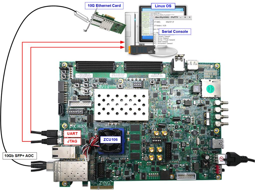
Figure 1‑2 NVMeTCP10G-IP demo on ZCU106
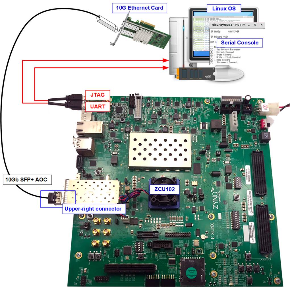
Figure 1‑3 NVMeTCP10G-IP demo on ZCU102
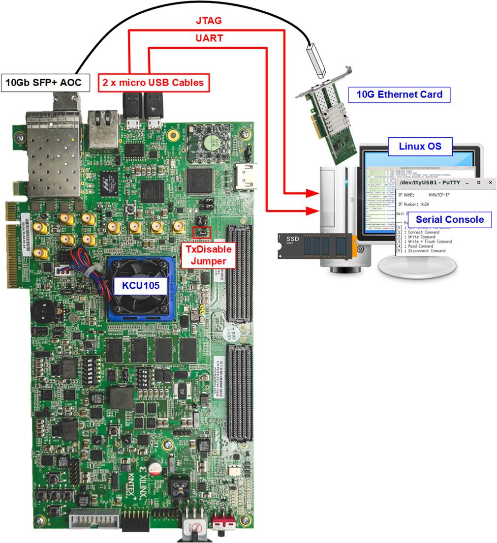
Figure 1‑4 NVMeTCP10G-IP demo on KCU105
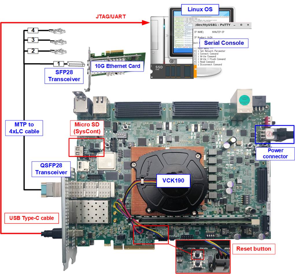
Figure 1‑5 NVMeTCP10G-IP demo on VCK190
2 FPGA setup
This section provides detailed instructions for preparing the FPGA board to run NVMeTCP10G-IP demo.
1) Check DIPSW and Jumper setting on FPGA board.
a) ZCU102/ZCU106 Boards (Figure 2‑1):
- Set SW6 to all ONs for USB-JTAG usage.
- For ZCU102 only, insert a jumper to J16 to enable Tx SFP+.
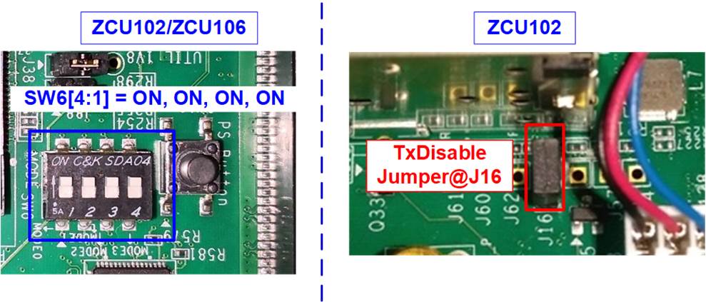
Figure 2‑1 ZCU102/ZCU106 board setting
b) KCU105 Boar (Figure 2‑2): Insert a jumper to J6 to enable Tx SFP+.
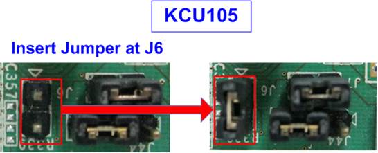
Figure 2‑2 Insert jumper to enable SFP+ on KCU105
2) Connect USB cables between the FPGA board and PC for JTAG programming and Serial console.
a) For ZCU106, ZCU102, and KCU105 boards: Use two micro USB cables.
b) For VCK190 board: Use a USB type-C cable.
3) Connect the power supply to the FPGA development board.
4) Connect a 10G Ethernet cable between the FPGA board and PC.
a) For ZCU102, KCU105, and ZCU106: Use a 10G SFP+ AOC cable. Utilize the specific SFP+ channel as indicated in Figure 2‑3.
b) For VCK190: Use a QSFP+ to SFP+ cable, connecting QSFP+ to FPGA and SFP+ no.1 to the PC�s 10G Ethernet card, as shown in Figure 2‑4.
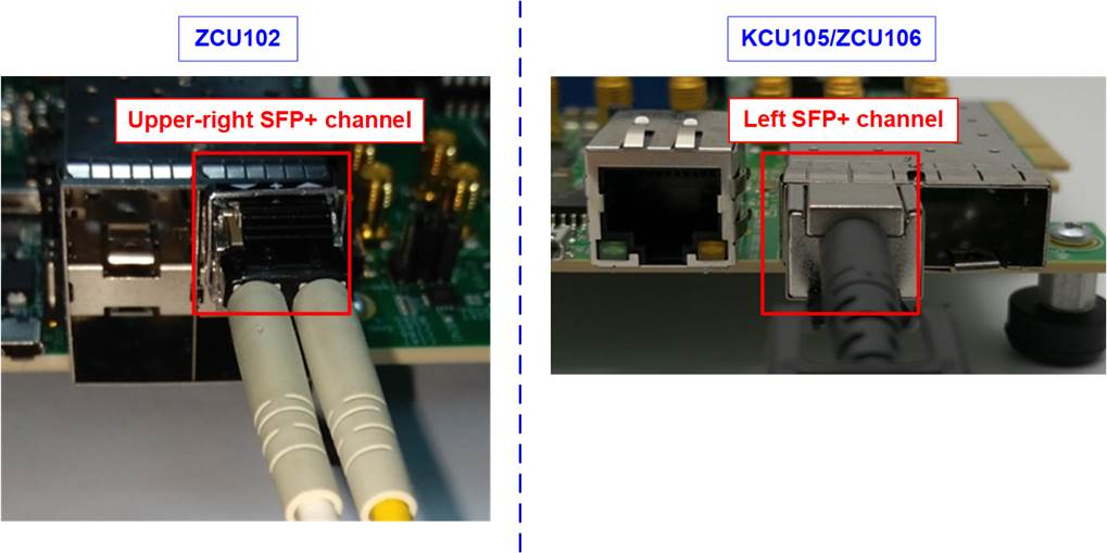
Figure 2‑3 SFP+ channel using on ZCU106/KCU105 board
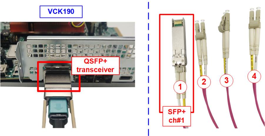
Figure 2‑4 10G connection by using QSFP28 to 4xSFP28 Cable
5) Power on the FPGA board. For VCK190 board only, follow these specific steps.
i) Insert a micro SD card into the system controller�s SD card socket (J206) and set the DIP switch (SW11) to ON OFF OFF OFF for booting from SysCont SD. For detailed guidance on setting up the SD card, visit the Xilinx Wiki page and see the topics: �Board Setup and Connection� and �Writing the image to micro SD card�
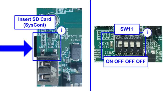
Figure 2‑5 VCK190 board setting
ii) Connect the VCK190 board to the PC using a USB cable. The PC should recognize three USB Serial Ports. Use the third port to monitor the board boot-up message.
iii) Open a Serial console and connect to the third USB Serial port with these settings: Baud rate=115,200, Data=8-bit, Non-parity, and Stop bits=1-bit.
Figure 2‑6 Serial console for boot-up on VCK190
iv) Power on the board and observe the boot-up message completion on the console.
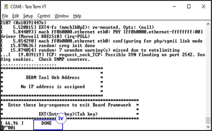
Figure 2‑7 Boot-up message of power-on sequence on VCK190
3 PC setup
This section outlines the configuration of the Serial console and FPGA programming tools on a PC necessary for running the demo. Instructions for both Windows OS and Linux OS are provided.
3.1 Serial console
When connecting the FPGA board to a PC, multiple COM ports (Windows OS) or USB Serial ports (Linux OS) associated with the FPGA connection will be detected.
3.1.1 Windows OS
Identify the correct COM port.
· For KCU105: Choose the standard COM port.
· For ZCU102/ZCU106: Select the COM port number assigned to Interface0.
· For VCK190: Select the lowest number of the newly detected COM ports.
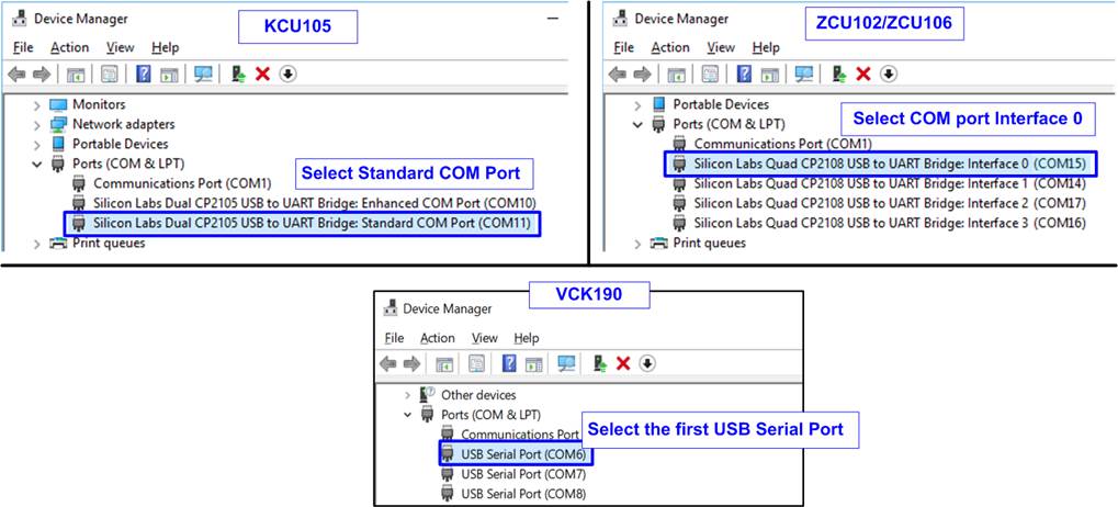
Figure 3‑1 The correct COM port when USB cable is plugged-in
Configure your Serial console with the following settings (illustrated in Figure 3‑2): Baud rate=115,200, Data=8-bit, Parity=None, and Stop bits= 1.
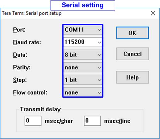
Figure 3‑2 Serial console setting
3.1.2 Linux OS
Upon connecting the FPGA board, several USB Serial ports will appear. Use the following command to list the USB Serial ports.
>> dmesg | grep ttyUSB
Port selection:
· For KCU105: Use the second port.
· For ZCU102/ZCU106: Use the first port.
· For VCK190: Use the second port.
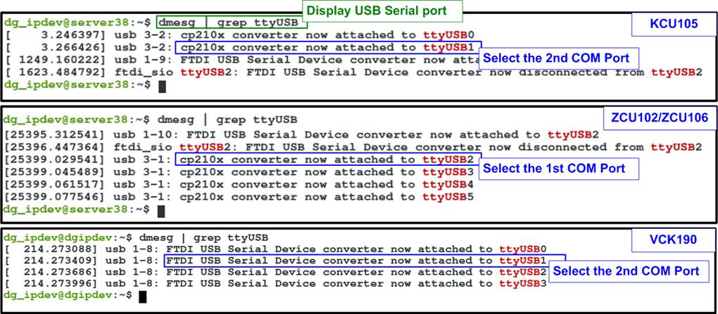
Figure 3‑3 Command to scan USB Serial ports on Linux OS
Figure 3‑4 demonstrates how to configured the Serial console using the Putty application with the same Serial setting as for Windows (Baud rate=115,200, Data=8-bit, Parity=None, and Stop bits= 1).
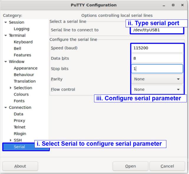
Figure 3‑4 Serial console setting on Linux OS
3.2 FPGA configuration
This section outlines the procedures to load the configuration file and the demo firmware onto the FPGA board. Depending on the FPGA board in use, the method for programming differs.
For KCU105 board: Utilize the Vivado tools for programming. Open the Vivado Hardware Manager and program the board with the required bit file as illustrated in Figure 3‑5.
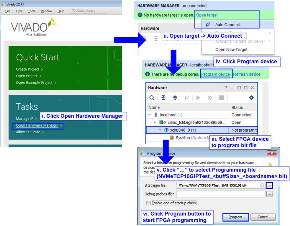
Figure 3‑5 KCU105 Configuration
For ZCU102, ZCU106, or VCK190 board: Use a script file via the TCL shell to load the bit file and the elf file.
Windows OS
Execute a batch file to load the configuration.
>> cd <directory containing the batch file>
>> nvmetcp10giptest_<buffsize>_<boardname>.bat
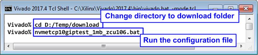
Figure 3‑6 ZCU102/ZCU106/VCK190 Configuration on Windows OS
Linux OS
Use a TCP script for loading the configuration.
>> cd <directory containing the tcl file>
>> exec xsdb nvmetcp10giptest_<buffsize>_<boardname>.tcl
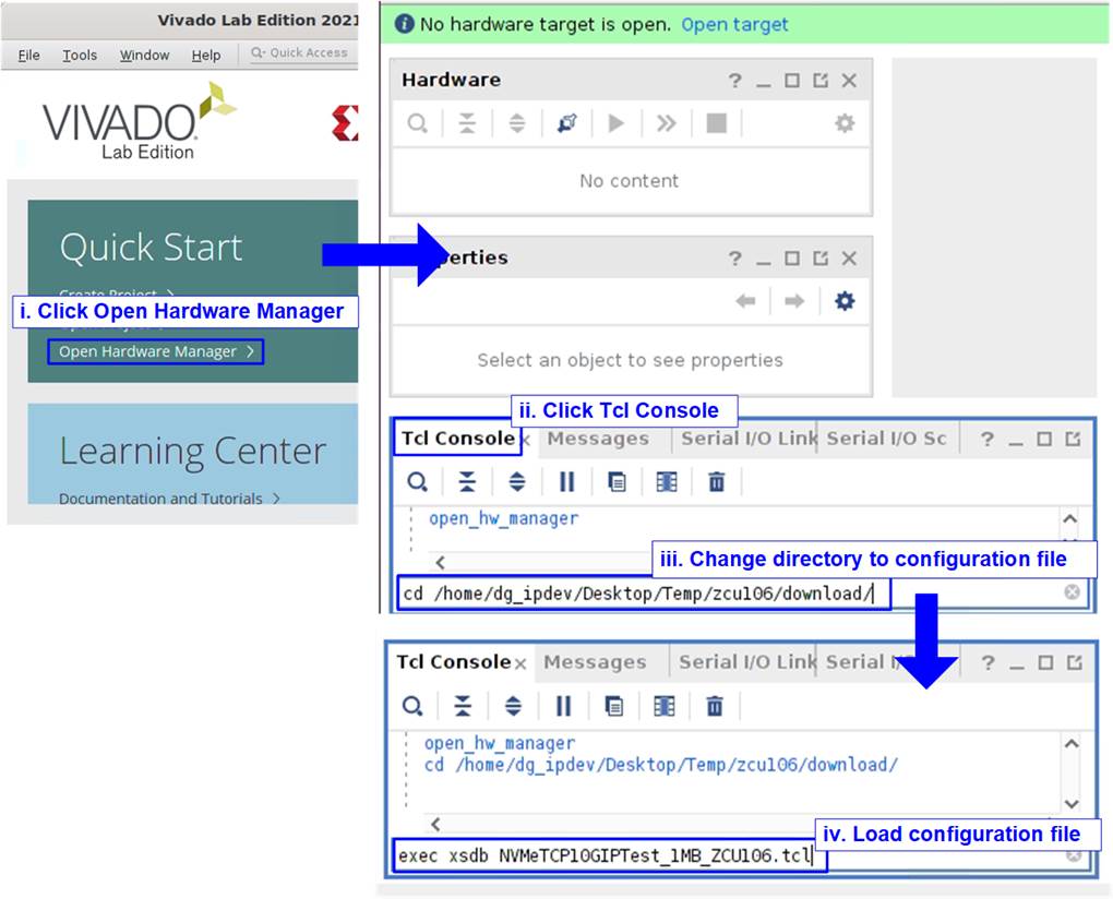
Figure 3‑7 ZCU102/ZCU106/VCK190 Configuration on Linux OS
Once the FPGA configuration is completed, a welcome message will be displayed on the console, as shown in Figure 3‑8.
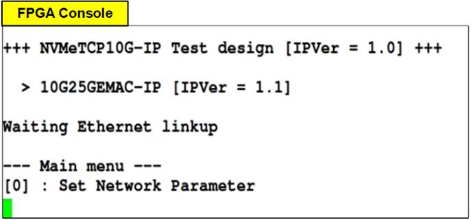
Figure 3‑8 Welcome screen
4 Revision History
|
Revision |
Date |
Description |
|
1.02 |
24-Apr-24 |
Support VCK190 |
|
1.01 |
24-Mar-22 |
Correct the information |
|
1.00 |
3-Nov-21 |
Initial version release |