
Core Facts |
|
|
Provided with Core |
|
|
Documentation |
Reference Design Manual Demo Instruction Manual |
|
Design File Formats |
Encrypted File |
|
Instantiation Templates |
VHDL |
|
Reference Designs & Application Notes |
Vivado Project, See Reference Design Manual |
|
Additional Items |
Demo on KCU116, FB2CGHH@KU15P card |
|
Support |
|
|
Support Provided by Design Gateway Co., Ltd. |
|
Design Gateway Co.,Ltd
E-mail: ip-sales@design-gateway.com
URL: design-gateway.com
Features
· NVMe/TCP (NVMe over TCP) host controller (Initiator), based on NVMe-oF specification rev 1.1 and NVMe specification rev 1.4
· Access an NVMe SSD on the target (Subsystem), selected by NVMe name (NQN)
· Command: Write and Read
· High performance: Write at 2500 Mbyte/s and
Read at 2600 Mbyte/s (1Mbyte buffer)
· Data interface: Memory-mapped interface
· Data size per command: Fixed at 8 Kbytes
· Maximum command: 128 or less, limited by Read buffer size for Read command
· Configurable Read buffer size: 64Kbytes (up to 8 Read Cmds) – 1Mbytes (up to 64 Read Cmds)
· Supported NVMe/TCP target:
· IOCCSZ (I/O Queue Command Capsule Support Size): More than or equal to 516 (204h)
· MQES (Maximum Queue Entries Supported): More than or equal to 128 (80h)
· MAXCMD (Maximum Outstanding Commands): More than or equal to 128 (80h)
· Authentication: Not required
· Networking: 25Gb Ethernet speed and jumbo frame packet support
· Ethernet MAC interface: 64-bit AXI4 Stream interface at 390.625 MHz
· User clock frequency: More than or equal to 195.3125 MHz (EMAC clock frequency/2)
· Available reference design: KCU116 board, FB2CGHH@KU15P card, Alveo U50 card
· Customized service
· The network that does not support jumbo frame packet
Table 1: Example Implementation Statistics
|
Family |
Example Device |
Read BufSize |
Fmax (MHz) |
CLB Regs |
CLB LUTs |
CLB1 |
IOB |
BRAMTile |
URAM |
Design Tools |
|
Kintex-UltraScale+ |
XCKU5P-FFVB676-2E |
64KB (min) |
350 |
19876 |
14124 |
3485 |
- |
26 |
4 |
Vivado2021.1 |
|
Kintex-UltraScale+ |
XCKU5P-FFVB676-2E |
1MB (max) |
285 |
20046 |
14292 |
3479 |
- |
26 |
34 |
Vivado2021.1 |
Notes:
1) Actual logic resource dependent on percentage of unrelated logic
Applications
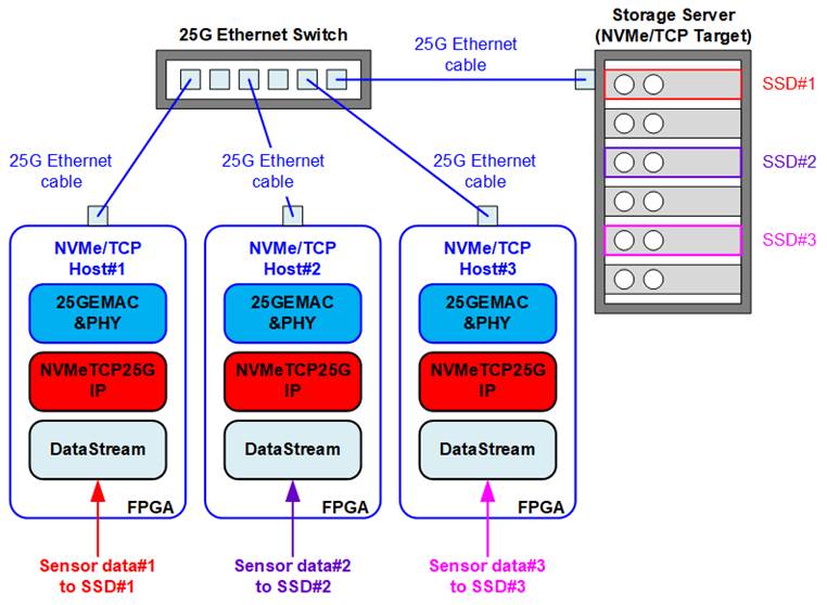
Figure 1: NVMeTCP IP for 25G Application
The storage server is designed to store large capacity data from various sources, utilizing multiple SSDs. Typically, servers are installed in a control room while the data sources are on-site recorded. In the absence of a network system, direct connection between the data source system and storage server is necessary to transfer recorded data to the SSD. This process can be time-consuming as each data source must be connected individually.
To solve this issue, a record system can be developed by integrating NVMeTCP25G IP to FPGA platform. This system facilitates ultra-fast data transfer to the storage server via a 25G Ethernet networking. Multiple NVMe/TCP host systems can access the storage server simultaneously, making it more convenient for hosts to transfer data to the SSD via the network. Additionally, the time required for transferring recorded data from sensors at the FPGA to the storage server is greatly reduced.
NVMeTCP25G IP is capable of transferring data to a specific SSD, identified by SSD name (NQN: NVMe Qualified Name) configured by the target system. In Figure 1, three NVMeTCP25G IPs can be used to transfer three data streams to three SSDs simultaneously. To switch between active SSDs, the current connection of NVMeTCP25G IP must be terminated before establishing a new connection to the new SSD.
General Description
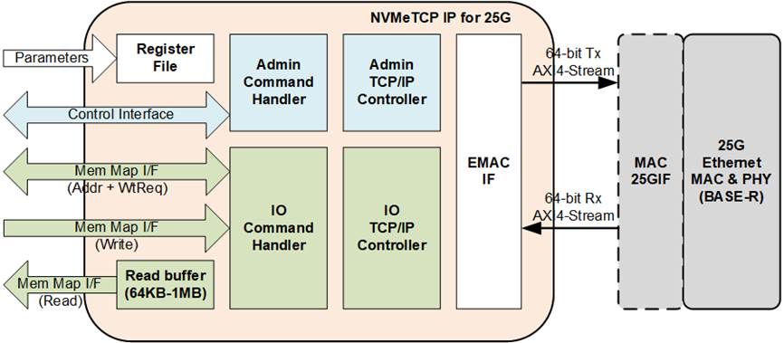
Figure 2: NVMeTCP IP for 25G Block Diagram
The NVMeTCP25G IP is used as a host controller, also known as an NVMe/TCP initiator, to access an SSD inside an NVMe/TCP target, also known as an NVMe/TCP subsystem, via 25Gb Ethernet. The IP’s user interface is divided into three groups: Parameters interface, Control interface, and Memory map interface. The Parameters interface assigns network parameters and timeout values during the connection establishment process, while the Control interface creates and terminates connections with the target system, and includes status and error monitoring. The Memory map interface is used to send Write and Read commands and transfer data.
To connect with the NVMe/TCP target, two TCP ports are established. The first port is the Admin connection handling connection establishment and termination, as well as Keep alive command to keep the connection active. The second port is the IO connection handling Write and Read commands. Two TCP/IP controllers and two Command Handlers are used independently control the two TCP ports, with the EMAC I/F serving as the port multiplexer to transfer Ethernet packets of both ports to the same EMAC.
NVMe/TCP Protocol Data Units (PDU) are assigned as TCP Payload in TCP/IP packets, according to the NVMe/TCP protocol, for reliable networking data transfer between the host and the target systems. The TCP/IP packet and PDU are constructed individually by the different controllers, so each PDU may be transmitted using a part of a TCP/IP packet, a TCP/IP packet, or multiple TCP/IP packets. In Figure 2, Admin/IO command handlers create and decode PDUs following the NVMe/TCP protocol, while Admin/IO TCP/IP controllers create and decode TCP/IP packets following the TCP/IP protocol.
The Register File interface receives user parameters to initiate the connection establishment, with a Read buffer for re-orderring received data in Read command to have the same sequence as the order of requested command. The IO command handler supports up to 128 Write/Read commands, with the maximum command in the queue limited by the Read buffer size. Larger buffer sizes may increase read performance but also affect resource utilization.
The NVMeTCP25G IP operates in two clock domains, EMAC interface clock and the user logic clock. The EMAC interface clock frequency is 390.625 MHz for 25G Ethernet speed, while the user logic bandwidth must be equal to or higher than the EMAC interface bandwidth. Thus, the user logic clock frequency must be equal to or higher than 195.3125 MHz.
The reference design on FPGA evaluation boards are available for evaluation before purchasing.
Functional Description
The operation flow of the NVMeTCP25G IP after IP reset is de-asserted is presented in Figure 3. The flow consists of two phases – No connection and Connection ready. To start the NVMe/TCP host function, the user must enable the connection. Once the connection is established, NVMeTCP25G IP creates two TCP ports for communicating with NVMe/TCP target, and upon successful creation of these ports, the IP changes from No connection phase to Connection ready phase.
During the Connection ready phase, there are two types of commands that can be run– Admin commands and IO commands. The Keep alive command is an auto-run command that always runs in the background during the Connection ready phase. IO commands (Write and Read commands) are controlled by the user, and multiple Write and Read commands can be sent until the command queue has reach its capacity (the number of operating commands = 128 or Read buffer is full).
When the user disables the connection, the opreation to terminate the connection is initiated, and after completion of the termination process, the IP returns to the No connection phase.
The operation flow is described in detail as follows.
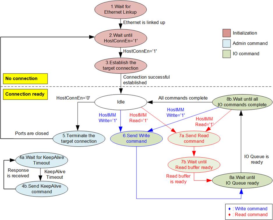
Figure 3: NVMeTCP25G IP Operation Flow
1) The IP waits until the Ethernet connection shows a link up status. Once the linkup signal is asserted, the EMAC IP core must be ready for transferring data via EMAC interface.
2) The IP monitors the HostConnEn signal, which is equal to a default value of 0b. When the HostConnEn changes from 0b to 1b by the user, the IP starts the connection establishment process.
3) To connect with the target, the Admin port is opened to create the communication channel. After the TCP connection is ready, the PDU is used to initialize the connection and connect with the target. It waits until the response to accept the connection request is received. Before transferring the data using Write/Read command with the NVMe/TCP target, the IO port must be created. Similar to Admin port, the IO connection must be initialized by sending the PDU, and the target must return the response to accept the IO connection. After completing the initialization process, the IP changes to Connection ready status.
Note: During connection initialization, the host and the target exchange NVMe Qualified Name (NQN). NQN of the host and the target are assigned by the user (HostNQN and TrgNQN: NVMeTCP25G IP input/parameters). NQN should be set by a unique value.
4) During the active connection, the Keep alive command is always sent every specific time, assigned by a constant value to the IP. The KeepAlive timer runs when the connection is ready. When a timeout is detected, the IP sends the Keep alive command to NVMe/TCP target. The operation is successful when the response is returned. If there is no response returned until the IP times out, the error will be asserted, and two TCP ports will be closed.
5) When there is no more data for transferring and the IP is in Idle status (HostBusy=0b), the user can de-assert HostConnEn to 0b to terminate the connection with the NVMe/TCP target system. The IP closes the IO port and then the Admin port. After that, the IP changes to the No connection status.
6) To send the Write command in Connection ready phase, the user asserts HostMMWrite=1b and transfers the Write data to the target. After that, the IP skips to step 8) to check the remaining size of IO command queue.
7) To send Read command in Connection ready phase, the user asserts HostMMRead=1b to send the Read command to the target. After that, the IP calculates the remaining Read buffer size. If the size is not enough for sending the next Read command, the IP will wait until the buffer has enough free space. The IP then moves to step 8) to check the remaining size of the IO command queue.
8) If the number of operated IO command in the queue is less than 128, the IP can receive new Write/Read commands. However, if the IP queue is full, the IP must wait until there is free space. After all Write and Read commands in the IO queue have been executed successfully, the IP returns to Idle status, which allows the user to disable the connection.
Figure 2 shows that the IP supports two protocols through two separate hardware components: NVMe/TCP protocol through the Command handler, and TCP/IP protocol through the TCP/IP controller.
NVMe/TCP
The NVMe/TCP protocol is composed of three protocol layers: NVMe (Admin command and IO command), NVMe over Fabrics, and NVMe/TCP transport. Each protocol layer is implemented through pure hardwired logics and has three user interfaces: Parameters, Control, and Memory mapped. These interfaces are handled by different hardware modules, including Register File, Admin Command Handler, IP Command Handler, and Read buffer.
· Register File
The Register File module loads the user-defined parameters, such as the IP address for creating Admin and IO connections, and forwards them to both the Admin and IO command handlers. The parameters are not used after the connections are established successfully. The module also loads the Timeout value to determine the waiting time of the response returned by the target system.
· Admin Command Handler
The Admin Command Handler is responsible for creating and terminating the Admin connection, which is established before the IP connection. Its operations are separated into three processes: Connection establishment (the most complex process), Keep alive command (to keep the connection active for running Write/Read command), and the connection termination (the last process). The KeepAliveSet parameter in the HDL code can be configured to set the time period for sending the Keep alive command which ranges from 0 – 3600 seconds. The Keep alive feature can interrupt the packet transferring while processing Write/Read command, so the write/read performance may be slightly reduced.
The logics inside Admin command handler consists of three parts. First is a controller to manage the PDU order for each process. Second is a Tx module for creating the PDU for initializing connection, terminating connection, transmitting command, and transmitting data. Third is an Rx module for decoding the PDU which may be the response of connection initialization, the response of the command, or the returned data. The Admin connection and IO connection are terminated if the controller waits for the received PDU until timeout.
· IO Command Handler
The IP Command Handler module has four processes: connection establishment, Write command, Read command, and connection termination. Similar to Admin command handler, it consists of the controller, Tx module, and Rx module. Its main function is to handle the Write and Read commands to transfer data with the best performance. The module is designed to support up to 128 Write and Read commands in the queue, but the data packet from the target may be returned out-of-order. Therefore, it needs to include the Read buffer to re-order the packet. When the Read buffer is full, the new command cannot be received. The module also has a timer to check the timeout condition and terminate the Admin and IP connections if the received PDU is not received within the set waiting time.
· Read buffer
The buffer size can be configured by the RdBufDepth parameters in the HDL code, with valid values ranging from 3 to 7. More details are shown in Table 2.
Table 2: RxBufDepth parameter description
|
RdBufDepth |
Buffer size |
Maximum Read command |
Estimated Read Performance*(1) |
|
3 |
64 Kbyte |
8 commands |
1400 Mbyte/s |
|
4 |
128 Kbyte |
16 commands |
1600 Mbyte/s |
|
5 |
256 Kbyte |
32 commands |
2300 Mbyte/s |
|
6 |
512 Kbyte |
64 commands |
|
|
7 |
1 Mbyte |
128 commands |
2500 Mbyte/s |
Remark *(1): Estimated Read performance is the performance in our test environment. The real performance depends on the resource of the target system.
The maximum value is 7 (1 Mbyte size), which allows for sending 128 Read commands to the IO command queue. While the minimum value is 3 (64 Kbyte) which allows for sending up to 8 Read commands in the queue. The Read buffer size limits the maximum number of Read commands that can be sent in the queue and affects the maximum read performance. Larger buffer size may lead to better read performance, while Write performance does not depend on Read buffer size.
TCP/IP
The TCP/IP protocol is handled by pure hardwired logics. Two TCP ports are handled simultaneously, so two TCP/IP Controller are applied. To transfer packets from two sources to an EMAC via 64-bit AXI4-Stream interface, an EMAC IF is integrated as a packet multiplexer.
· Admin TCP/IP Controller
The Admin TCP/IP controller consists of three logic parts. First is the main controller to control each operation, including opening/closing the ports and sending/receiving data. Secondly, the Tx module encapsulates the PDU into and Ethernet packet by adding TCP, IP, and Ethernet headers. Finally, the Rx module decodes the Ethernet packet and extracts only the TCP payload to be returned to the Admin command handler.
Since TCP/IP is a lossless protocol, the logic supports data retransmission for data recovery when lost data is found. Besides, TCP/IP has flow control by reading the free size of the received buffer from the receiver before sending more data. The Admin port handles connection initialization, connection termination, and Keep-alive transmission, but there are fewer packets transmitted than the IO port. To optimize the resource utilization, the TCP buffer size inside the Admin TCP/IP controller is not large.
The TCP/IP controller decodes the MAC address of the NVMe/TCP target using two methods depending on TrgMACMode (NVMeTCP25G IP input), which is set by user. In Fixed MAC mode, the target MAC address is fed directly by user, while in ARP mode, the TCP/IP controller uses ab ARP packet to translate the MAC address of the NVMe/TCP target from IP address.
· IO TCP/IP Controller
Compared to the Admin TCP/IP controller, the IO TCP/IP controller requires high-speed performance to transfer data in Write and Read commands. Therefore, the TCP buffer size in the IO TCP/IP controller is larger to enable the transfer of Ethernet packet with the NVMe/TCP target continuously under the flow control process. To achieve optimal performance, the Ethernet packet transmitted by the IO TCP/IP controller is Jumbo-frame, so both the network device and NVMe/TCP target must support Jumbo-frame packets.
Note: Please contact our sales team if the user needs to use a target system that does not support Jumbo-frame packets.
· EMAC IF
The EMAC IF is designed to receive packets from both the Admin and IO TCP/IP controllers and forward them to the EMAC. Likewise, packets received from EMAC are forwarded to Admin and IO TCP/IP controllers.
User Logic
The interface logic between the user logic and the NVMeTCP25G IP is designed using a Memory mapped interface for Write and Read commands. This logic assigns the address and asserts a request to the IP to initiate the operation, similar to a standard memory mapped bus interface. The parameters for the NVMeTCP25G IP can be assigned using constant values. The control interface is applied to monitor the status and detect any error conditions. If no error condition is found, the user can enable and disable the connection with the target using a single signal called HostConnEn. Therefore, the user logic design for transferring data with the NVMe/TCP target system using the NVMeTCP25G IP is simple.
10G/25G Ethernet MAC and PHY
To connect another side of the NVMeTCP25G IP, either the DG 10G25GEMAC IP or Xilinx 10G/25G Ethernet subsystem can be used. If using DG 10G25GEMAC IP, the NVMeTCP25G IP can directly connect to it. However, when using the Xilinx 10G/25G Ethernet subsystem, additional logic including small FIFO (MAC25GIF in Figure 2) is required for the connection.
Note: The 25G Ethernet PCS/PMA for 25GBASE-R is no charge Xilinx LogiCORE.
More information about the DG 10G25GEMAC IP core can be found on the following website.
https://dgway.com/products/IP/GEMAC-IP/dg_10g25gemacip_data_sheet_xilinx.pdf
For More details on the 10/25G Ethernet Subsystem, including the Ethernet MAC and Ethernet PCS/PMA, please refer to the following website.
https://www.xilinx.com/products/intellectual-property/ef-di-25gemac.html
Core I/O Signals
Descriptions of all parameters and I/O signals are provided in Table 3 - Table 5.
Table 3: Core Parameters
|
Value |
Description |
|
|
HostNQNH[1783:128] |
Unicode char |
Upper 207 bytes of NVMe Qualifed Name (NQN) of the host system Note: If HostNQN can be assigned within 16 bytes which is ft to HostNQNL input size, the value of HostNQNH can be fixed to all zero value. |
|
KeepAliveSet |
0 – 3600 |
Time period to send Keep-alive in second unit. Set 0 to disable Keep-alive transmission feature. |
|
RdBufDepth |
3 - 7 |
Setting Read buffer size. More details are shown in Table 2. |
Table 4: User I/O Signals (Synchronous to Clk)
|
Signal |
Dir |
Description |
|
Common Interface |
||
|
RstB |
In |
Reset IP core. Active Low. |
|
Clk |
In |
User clock for running NVMeTCP25G IP. The frequency must be more than or equal to 195.3125 MHz. |
|
Parameters Interface Note: All inputs must be valid when HostConnEn=1b and HostConnStatus=0b. |
||
|
HostMAC[47:0] |
In |
MAC address of the host system. |
|
HostIPAddr[31:0] |
In |
IP address of the host system. |
|
HostAdmPort[15:0] |
In |
Admin Port number of the host system |
|
HostIOPort[15:0] |
In |
IO Port number for the host system |
|
TrgMACMode |
In |
Target MAC Address Mode. 0b: Target MAC address by ARP, 1b: Fixed target MAC addrerss by user (TrgMAC[47:0]). |
|
TrgMAC[47:0] |
In |
MAC address of the target system using Fixed MAC mode (TrgMACMode=1b). |
|
TrgIPAddr[31:0] |
In |
IP address of the target system |
|
TCPTimeOutSet[31:0] |
In |
Timeout value to initiate retransmission process. Time unit is 1/Clk frequency or 5.12 ns for 195.3125 MHz. It is recommended to use 3 times of RTT (Round-trip time) or 1 sec when 3 times of RTT is less than 1 sec. |
|
NVMeTimeOutSet[31:0] |
In |
Timeout value to wait the response returned from the target, and then error is asserted. Time unit is equal to 1/(Clk frequency) or 5.12 ns for 195.3125 MHz. When NVMeTimeOutSet is set to 0, Timeout is disabled. It is recommended to use 4 times of TCPTimeOutSet to allow TCP/IP retransmission before error asserting. |
|
HostNQNL[127:0] |
In |
The lower 16 bytes of NVMe Qualifed Name (NQN) of the host system, defined as a string of Unicode characters. Total size of HostNQN is 223 bytes, 207 bytes by parameter assignment (HostNQNH) and 16 bytes by this input (HostNQNL). When the length of the name is less than the maximum size, the remaining characters must be set to 00h, similar to TrgNQN. This value is used by the target system to grant permission to specific hosts for accessing the SSD. |
|
TrgNQN[1783:0] |
In |
NVMe Qualifed Name (NQN) of the SSD inside the target system, defined as a string of Unicode characters. Maximum size of TrgNQN is 223 bytes. When the name is shorter than maximum size, the remaining characters are set to 00h. For instance, when NQN is “dgnvmettest”, set TrgNQN[7:0]=’d’, TrgNQN[15:8]=’g’, …, TrgNQN[87:80]=’t’. While remaining characters (TrgNQN[1783:88]) = 0 (null). The host uses this value to select the active SSD at the target system. NQN of the SSD is configured by NVMe/TCP target system. |
|
Dir |
Description |
|
|
Control Interface |
||
|
IPVersion[31:0] |
Out |
IP version number |
|
TestPin[127:0] |
Out |
Reserved to be IP Test point |
|
HostConnEn |
In |
Enable/Disable the connection with the target. Change from 0b to 1b to create the connection with the target. Change from 1b to 0b to terminate the connection with the target Before changing the signal, please confirm that the IP is Idle (HostBusy=0b). After that, HostBusy is asserted to 1b to start connection establishment/termination. HostBusy is de-asserted to 0b after finishing the operation. |
|
HostConnStatus |
Out |
Connection Status. 0b: No connection with the target, 1b: The connection is active. |
|
HostBusy |
Out |
IP busy status. 0b: Idle, 1b: Busy. Asserted to 1b when HostConnEn changes the value to enable/disable the connection, or the user sends Write/Read command. De-asserted to 0b after the IP completes the operation. |
|
HostError |
Out |
Error flag. Asserted to 1b when HostErrorType is not equal to 0. The flag is cleared by asserting RstB to 0b. |
|
HostErrorType[31:0] |
Out |
[0] – Error when the target is not found. [1] – Error when the target requires authentication. [2] – Error when some target parameters are not supported. Please see more details in TrgCAPStatus signal. - IOCCSZ (I/O Queue Command Capsule Supported Size) is less than 516. - MQES (Maximum Queue Entries Supported) is less than 128. - MAXCMD (Maximum Outstanding Commands) is less than 128. [7:3] - Reserved [8] – Error when Admin port cannot be established successfully. [9] – Error when Admin port does not receive the response until timeout. [10] – Error when status register of Admin completion entry is not correct. Please see more details in TrgAdmStatus signal. [11] – Error when Admin received packet is not aligned to 8 bytes(1). [12] – Error when Admin port receives unknown packet. [13] – Error when Admin port receives terminate request. [15:14] – Reserved [16] – Error when IO port cannot be established successfully. [17] – Error when IO port does not receive the response until timeout. [18] – Error when status register of IO completion entry is not correct. Please see more details in TrgIOStatus signal. [19] – Error when IO received packet is not aligned to 8 bytes(1). [20] – Error when IO port receives unknown packet. [21] – Error when IO port receives terminate request. [31:22] – Reserved Remark: (1): Please contact our sales if your target system returns the packet that is not aligned to 8 bytes (64-bit). |
|
Dir |
Description |
|
|
Control Interface |
||
|
TrgLBASize[47:0] |
Out |
Total capacity of SSD in 512-byte unit. Bit[3:0] are equal to 0 to align 8Kbyte unit because the IP supports transferring data in 8Kbyte unit. Default value is 0. This signal is valid after finishing the connection establishment process. |
|
TrgCAPStatus[63:0] |
Out |
[31:0] – IOCCSZ (I/O Queue Command Capsule Supported Size) [47:32] – MQES (Maximum Queue Entries Supported) [63:48] – MAXCMD (Maximum Outstanding Commands) |
|
TrgAdmStatus[15:0] |
Out |
Status output from Admin command [0] - Reserved [15:1] – Status field value of Admin Completion Entry |
|
TrgIOStatus[15:0] |
Out |
Status output from I/O command [0] - Reserved [15:1] – Status field value of IO Completion Entry |
|
Memory mapped Interface |
||
|
HostMMAddr[47:0] |
In |
The address in 512-byte unit for Write/Read command. Valid when HostMMWrite=1b in Write command or HostMMRead=1b in Read command. HostMMAddr[3:0] must be always set to 0 to align 8 Kbyte. Maximum value of HostMMAddr is equal to TrgLBASize – 16 (8 Kbyte). |
|
HostMMRead |
In |
Assert to 1b for sending Read command. After the IP receives one Read command (HostMMRead=1b and HostMMWtReq=0b), 8Kbyte read data is returned on HostMMRdData with asserting HostMMRdValid to 1b. Note: HostMMRead must not be asserted to 1b when Write command with 8Kbyte data is in request. |
|
HostMMWrite |
In |
Assert to 1b for sending Write command with 8Kbyte write data to the IP. Note: HostMMWrite must not be asserted to 1b at the same time as HostMMRead=1b |
|
HostMMWtReq |
Out |
The response of Write/Read request. 0b: Accept Write/Read command request and Write data. 1b: Not ready to receive Write/Read command or Write data. |
|
HostMMWrData[127:0] |
In |
Write data in Write command. Valid when HostMMWrite=1b. The value must be latched if HostMMWtReq=1b. |
|
HostMMRdData[127:0] |
Out |
Read data returned after receiving Read command. Valid when HostMMRdValid=1b. |
|
HostMMRdValid |
Out |
Valid signal of HostMMRdData. Asserted to 1b to return Read data in Read command. The user can pause the Read data via HostMMRdPause signal and the latency time from HostMMRdPause to HostMMRdValid is 2 clock cycles. |
|
HostMMRdPause |
In |
Asserted to 1b when user is not ready to receive Read data. |
Table 5: EMAC I/O Signals (Synchronous to MacClk)
|
Signal |
Dir |
Description |
|
MacClk |
In |
Receive clock from EMAC core which is equal to 390.625MHz for 25Gb Ethernet |
|
EthLinkup |
In |
Ethernet Linkup status. Asserted to 1b when the ethernet link is established. |
|
MacTxData[63:0] |
Out |
Transmitted data to EMAC. Valid when MacTxValid=1b. |
|
MacTxKeep[7:0] |
Out |
Byte enable of MacTxData. Valid when MacTxValid=1b. Bit[0],[1],…,[7]=1b when MacTxData[7:0],[15:8],…,[63:56] are valid. |
|
MacTxValid |
Out |
Valid signal of MacTxData. |
|
MacTxLast |
Out |
Asserted to 1b to indicate the final data of the packet. Valid when MacTxValid=1b. |
|
MacTxReady |
In |
Handshaking signal. Asserted to 1b when MacTxData has been accepted. This signal must not be de-asserted to 0b before transmitting the final data of a packet |
|
MacRxData |
In |
Received data. Valid when MacRxValid=1b. |
|
MacRxValid |
In |
Valid signal of MacRxData. After transferring the first data of packet, the signal must be asserted to 1b until transferring the final data of a packet to transfer a packet continuously. |
|
MacRxLast |
In |
Asserted to 1b to indicate the final data of the packet. Valid when MacRxValid =1b. |
|
MacRxUser |
In |
Control signal asserted at the end of received frame (MacRxValid=1b and MacRxLast=1b) to indicate that the frame has CRC error. 0b: Normal packet, 1b: Error packet. |
|
MacRxReady |
Out |
Handshaking signal. Asserted to 1b when MacRxData has been accepted. MacRxReady is de-asserted to 0b for 2 clock cycles after receiving the final data of the frame. |
Timing Diagram
Reset process
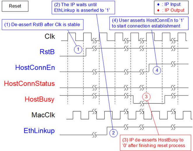
Figure 4: Timing diagram of Reset process
1) The Clk signal must be stable before setting RstB to 1b. Once RstB is de-asserted to 1b, the IP initiates the reset process.
2) To confirm that the Ethernet link has been established, the IP checks EthLinkup. The IP waits until EthLinkup is set to 1b before proceeding.
3) During the reset process, HostBusy is asserted to 1b. Once the IP completes the reset process, HostBusy is de-asserted to 0b, indicating that the IP is ready to connect with the target system.
4) The user can set HostConnEn to 1b to begin the connection establishment process with the target system. It is recommended to de-assert HostConnEn to 0b during the reset operation.
Connection Establishment
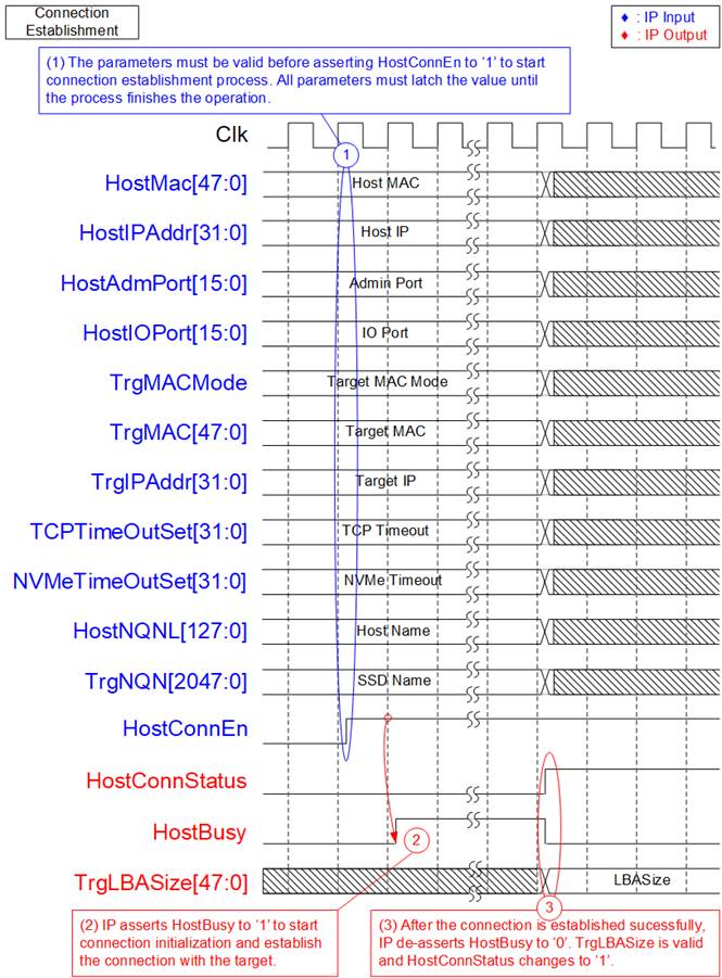
Figure 5: Timing diagram of Connection establishment
1) Before asserting HostConnEn to 1b, the values of HostConnStatus and HostBusy must be equal to 0b, indicating that the IP is idle and the connection is not active. All parameters (HostMAC, HostIPAddr, HostAdmPort, HostIOPort, TrgMACMode, TrgMAC, TrgIOAddr, TCPTimeOutSet, NVMeTimeOutSet, HostNQNL, and TrgNQN) must be valid when HostConnEn is set to 1b. After that, the parameter values must be latched until the connection establishment process is completed.
2) HostBusy is asserted to 1b during the connection establishment process, indicating that the process is not yet completed.
3) Once the connection establishment process is complete, HostConnStatus changes to 1b, and TrgLBASize becomes valid for reading. HostBusy is de-asserted to 0b, indicating that the connection is now ready for sending Write/Read commands.
If the connection establishment fails, the error signal is asserted, as shown in Figure 6. This failure may result from incorrect parameter settings. Once the error signal is set, the user must set RstB signal to reset the IP.
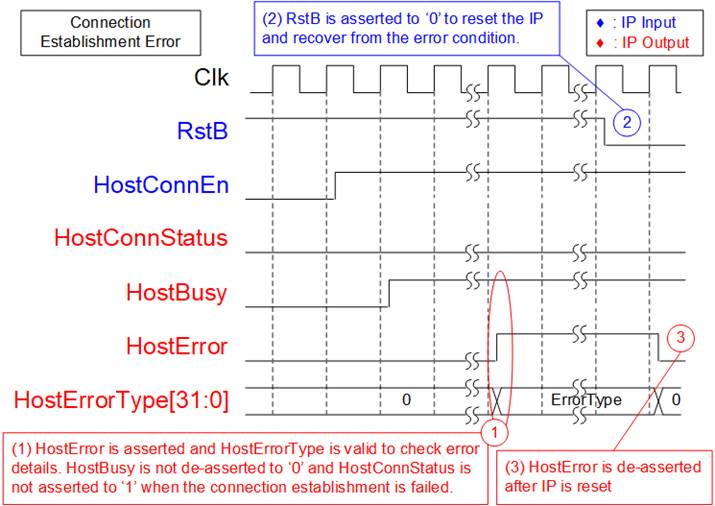
Figure 6: Error during running Connection establishment
1) HostError is asserted to 1b, and HostErrorType indicates the specific error details that occurred during the connection establishment process. Unlike the successful condition, HostConnStatus is not set to 1b, and HostBusy is not de-asserted to 0b in the event of a failure.
2) To recover from the error, the IP must be reset by setting RstB to 0b.
3) After resetting the IP, HostError is de-asserted to 0b, and the error status is cleared.
Write command
Data size of each Write command is fixed at 8 Kbytes (512 x 128-bit). The Write command is asserted along with the first data (D0) on HostMMWrData. If the IP is not ready to receive the command or the data, the IP will assert HostMMWtReq to 1b. Therefore, the user should latch the input until the IP is ready. After finishing the Write command, HostBusy will be de-asserted to 0b.
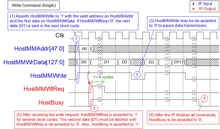
Figure 7: Timing diagram of Write command (Single mode)
1) To send a Write request, the user asserts HostMMWrite to 1b along with the start write address (A0) and the first write data (D0) on HostMMAddr and HostMMWrData, respectively. If HostMMWtReq is asserted to 1b, the first data must be latched until HostMMWtReq is de-asserted to 0b. If HostMMWtReq is de-asserted to 0b, the next write data (D1) will be sent in the next clock.
Note: HostMMAddr must be aligned to 8Kbyte size by setting bit[3:0] to 0000b.
2) After the IP accepts the Write request, it will assert HostMMWtReq to 1b to pre-process the Write command. Therefore, the second data (D1) must be latched until HostMMWrReq is de-asserted to 0b. HostBusy will also be asserted to 1b to prevent the user from terminating the connection before the Write command is completed.
Note: The minimum cycle that HostMMWtReq is asserted to 1b after receiving Write command request is equal to 6. After that, HostMMWtReq is de-asserted to 0b until sending the final data of this Write command.
3) If the next write data is not ready, the user can de-assert HostMMWrite to 0b. HostMMWrite can be asserted to 1b again with the valid write data when it is ready.
4) After the final data (D511) is received, the IP will de-asserts HostBusy to 0b when all commands are completely processed. The user can then terminate the connection if there is no more data to transfer.
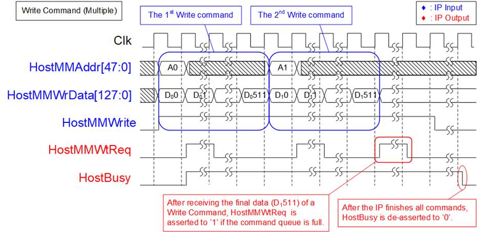
Figure 8: Timing diagram of Write command (Multiple mode)
Figure 8 shows an example when multiple Write commands are transmitted to the IP. To send the second command in the next clock cycle after the first command is completed, the user sets HostMMWrite to 1b. HostMMWtReq is asserted to 1b after receiving the first data, like the first Write command. However, if the command queue is full (128 commands), the IP will set HostMMWtReq to 1b at the end of the Write command. Once all the Write commands have been executed, HostBusy is de-asserted to 0b.
Read command
The data size of each Read command is fixed at 8 Kbytes (512 x 128-bit), similar to Write command. After Read command is requested, 8 Kbyte data (HostMMRdData) is returned to the user. HostMMWtReq is asserted to 1b when the IP is not ready to receive the next command. While 8 Kbytes Read data is transferring, user can assert HostMMRdPause to 1b to pause data transmission. After all Read commands are processed, HostBusy is de-asserted to 0b.
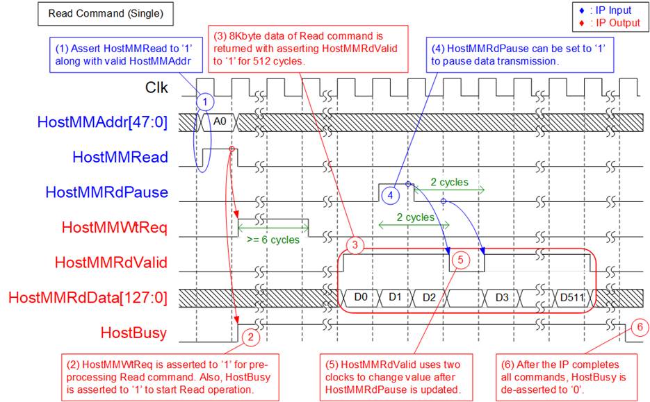
Figure 9: Timing diagram of Read command (Single mode)
1) To send a Read request, the user sets HostMMRead to 1b and ensures the start read address is valid on HostMMAddr.
Note: HostMMAddr must be aligned to 8Kbyte size by setting bit[3:0] to 0000b.
2) Once the IP accepts the read request, HostMMWtReq is asserted to 1b for pre-processing the Read command, similar to Write command. HostBusy is also asserted to 1b to protect the connection termination by the user.
Note: The minimum cycle that HostMMWtReq is asserted to 1b for pre-processing is equal to 6 cycles.
3) The 8Kbyte data of the Read command is returned on HostMMRdData by setting HostMMRdValid to 1b for 512 cycles.
4) If the user is not ready to receive read data, the user can set HostMMRdPause to 1b.
5) The IP uses two clock cycles to de-assert HostMMRdValid to 0b to pause data transmission. The HostMMRdValid is re-asserted to 1b after HostMMRdPause is de-asserted for two clock cycles.
6) The IP de-asserts HostBusy to 0b when all commands are completely processed. After that, the user can terminate the connection if there is no more data for transferring.
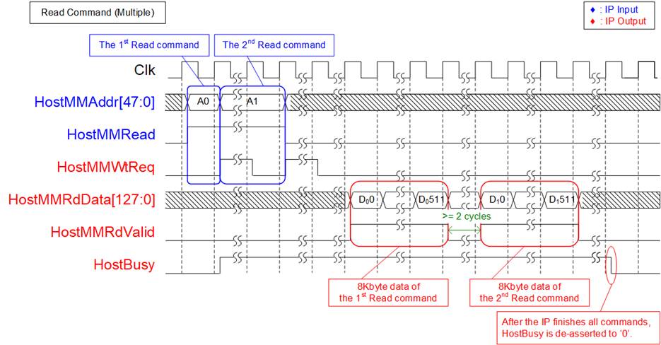
Figure 10: Timing diagram of Read command (Multiple mode)
Figure 10 shows an example when multiple Read command are transferred to the IP. To send the second command, the user asserts HostMMRead to 1b in the next clock cycle after the first command is accepted. However, the second command and the address must be latched at least 6 cycles, which is the pre-processing time of the IP. The command bus and data bus operate in parallel. The user can request a new Read command to the IP without waiting for the returned data on HostMMRdData.
When the target system returns the data of the Read command, the IP core re-arranges the data in the same order as the command request. The 8Kbyte data of the first Read command is returned before the 8Kbyte data of the second Read command. The gap size between each 8Kbyte received data is at least 2 clock cycles. Once all received data is returned, and all Read commands are entirely processed, HostBusy is de-asserted to 0b.
Mixed Write and Read command
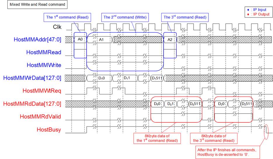
Figure 11: Timing diagram of Mixed Write and Read command
Figure 11 shows an example where mixed Write and Read command are requested by the user. HostMMAddr and HostMMWtReq are shared signals for Write and Read command. Thus, the user cannot assert HostMMWrite and HostMMRead to 1b to send Write and Read commands simultaneously. In Figure 11, the order of command is Read @ A0, Write @ A1, and Read @A2. After the IP receives the Write/Read command, HostMMWtReq is asserted to 1b to run pre-processing at least 6 clock cycles. It is also asserted to 1b if the command queue is full.
Similar to the Read command in Multiple mode, the order of received data in HostMMRdData is similar to the order of the command request. As shown in Figure 11, the 8Kbyte data of the first command is returned before the 8Kbyte data of the third command.
After finishing all IO command operations, HostBusy is de-asserted to 0b.
Connection Termination
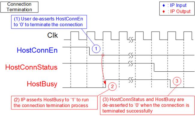
Figure 12: Shutdown command timing diagram
1) To ensure that there are no incomplete commands remaining, HostBusy must be de-asserted to 0b before de-asserting HostConnEn to 0b to request connection termination.
2) During the connection termination process, HostBusy is asserted to 1b by the IP.
3) After successful termination of the connection, HostConnStatus is de-asserted to 0b before and HostBusy is de-asserted to 0b.
Error
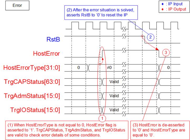
Figure 13: Timing diagram of HostError and HostErrorType
1) When an error is detected in the IP core, the HostErrorType is not equal to 0. HostError is then asserted to 1b to inform the user about the error condition. The user can read HostErrorType to identify the type of the error. Some error types provide additional information in the status signals, shown as follows.
HostErrorType[2]=1b : Read TrgCAPStatus to check unsupported Target system
HostErrorType[10]=1b : Read TrgAdmStatus to check Status register of Admin command
HostErrorType[18]=1b : Read TrgIOStatus to check Status register of IO command
2) Once the user has identified and resolved the error in the system, user can restart the IP by setting the RstB signal to 0b. As a result, all logics in the IP are reset.
3) After the IP has been restarted, HostError and HostErrorType are cleared, indicating that there are no error status found in the system.
EMAC Interface
EMAC interface of NVMeTCP25G IP uses a 64-bit AXI4-stream interface. However, it has a limitation that it cannot pause data transmission before the final data of a packet is transmitted. As a result, MacTxReady must always be asserted to 1b between the first data and the final data of a packet, as shown in Figure 14.
Due to this limitation, the NVMeTCP25G IP can be directly connected to the DG 10G25GEMAC IP core. However, a special logic with a small FIFO must be added to interface it with Xilinx 10G/25G Ethernet Subsystem.
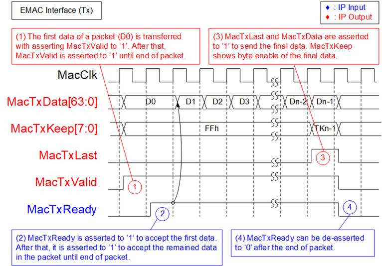
Figure 14: Transmit EMAC interface timing diagram
1) The IP asserts MacTxValid to 1b and sends the first data (D0) on MacTxData. All 64-bit data are valid, except the final data that may be valid for some bytes. Therefore, MacTxKeep is equal to FFh for every data, except the final data. The inputs latch the value until MacTxReady is asserted to 1b.
2) EMAC asserts MacTxReady to 1b to accept the first data. After that, MacTxReady is asserted to 1b to accept all remaining data in the packet until the end of the packet. Therefore, one packet data is transferred continuously.
3) The IP asserts MacTxValid and MacTxLast to 1b when the final data (Dn-1) of the packet is sent to MacRxData. MacTxKeep may not be equal to FFh when some upper bytes are not valid.
4) After finishing transferring the packet, MacTxReady may be de-asserted to 0b to pause data transmission of the next packet.
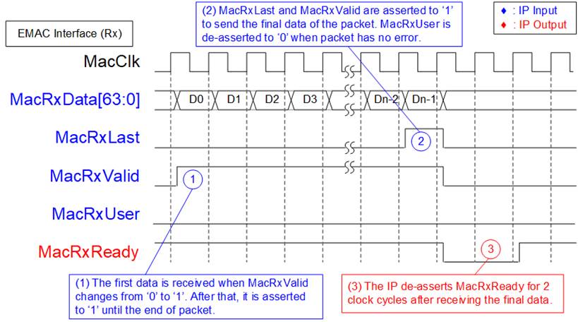
Figure 15: Receive EMAC interface timing diagram
1) The IP detects the first data (D0) of a packet on MacRxData when MacRxValid changes from 0b to 1b. To transfer the remaining data of the packet continuously, MacRxValid and MacRxReady must be equal to 1b until the end of the packet.
2) The final data (Dn-1) is received on MacRxData when MacRxValid and MacRxLast are both asserted to 1b. At the same time, MacRxUser is valid for reading. If there are no errors in the packet, MacRxUser is set to 0b. Otherwise, the packet is rejected by the IP.
3) After receiving the end of packet, the IP de-asserts MacRxReady for 2 cycles to complete the packet post-processing. As a result, the EMAC must be able to pause data packet transmission for 2 clock cycles.
Note: Typically, at least two cycle gap size is detected after finishing transferring Ethernet frame to allow EMAC to append the control word.
Verification Methods
The NVMeTCP25G IP Core functionality was verified by simulation and also proved on real board design by using KCU116 board, Silicom FB2CGHH@KU15P board, and Alveo U50 card.
Recommended Design Experience
Experience design engineers with a knowledge of Vivado Tools should easily integrate this IP into their design.
Ordering Information
This product is available directly from Design Gateway Co., Ltd. Please contact Design Gateway Co., Ltd. for pricing and additional information about this product using the contact information on the front page of this datasheet.
Revision History
|
Revision |
Date |
Description |
|
1.2 |
24-Feb-2023 |
Update core I/O signals and resource utilization |
|
1.1 |
11-May-2022 |
Update resource utilization |
|
1.0 |
25-Mar-2022 |
Initial Release |