NVMeTCP25G-IP Demo Instruction
2 NVMe/TCP Target Setup on Linux PC
2.2 Ethernet Interface Setting on Linux PC
2.3 NVMe/TCP Target Setting on Linux PC
2.4 Removing NVMe/TCP Target Configuration on Linux PC
1 Overview
This document provides instructions for running the NVMeTCP25G-IP demo, which demonstrates the use of an NVMe/TCP Host (Initiator) to access an NVMe SSD installed in an NVMe/TCP Target. The Target system for this demo uses a PC running Ubuntu 20.04.1 OS. The demo involves writing to and reading from the NVMe SSD over a 25G Ethernet connection, following the standard of NVMe/TCP protocol. These operations are managed via the FPGA console interface.
This guide is divided into two sections. Section 2 outlines how to set up the NVMe SSD in the Target PC for accessing by the NVMe/TCP and the process for safely removing the NVMe SSD from the NVMe/TCP target configuration on Ubuntu OS. Section 3 details the operations performed through the FPGA console, with step-by-step instructions for testing and explanations of the test results.
2 NVMe/TCP Target Setup on Linux PC
2.1 Application Installation
Prior to running the NVMeTCP25G-IP demo, certain applications must be installed on Linux PC. These applications only need to be installed once and do not require reinstallation for subsequent uses.
· Ethtool: This utility is used to optimize the performance of the network card. To install Ethtool, open a terminal and execute the following command:
![]()
· NVMe Command Line Interface (NVMe-CLI): This tool is used to manage NVMe SSDs on a Linux OS. To install NVMe-CLI, run the following command in the terminal:
![]()
2.2 Ethernet Interface Setting on Linux PC
To achieve optimal performance of the 25G Ethernet network card before running the demo, follow these steps below. Open a terminal to begin configuring the Ethernet interface.
1) Use the following command to list the logical name of the 25G Ethernet port on the Linux system:
![]()
Figure 1 displays the command output, where the 25G Ethernet interface connected to the NVMe/TCP host is identified as “enp1s0f0”.
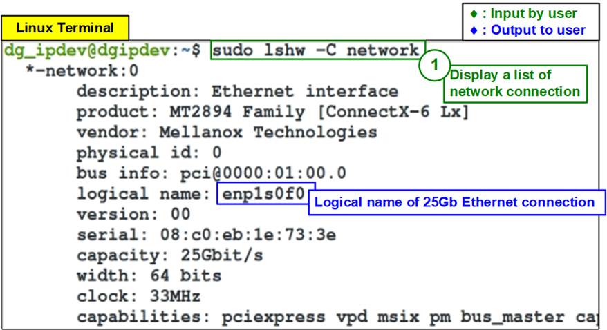
Figure 1 Display Logical Name of 25G Ethernet Port
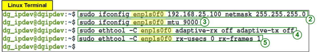
Figure 2 IP Address and Ethernet Interface Setting
2) Set the IP address and subnet mask for the desired Ethernet port by using the command:
“ifconfig <interface> <ipaddr_value> netmask <netmask_value>”.
a) Interface = enp1s0f0
b) IP address = 192.168.25.100
c) Subnet mask = 255.255.255.0
![]()
3) Enable jumbo frames by setting the Maximum Transfer Unit (MTU) to 9000 using the following command: “ifconfig <interface > mtu <mtu_value>”.
![]()
4) Disable the Rx-Tx latency improvement algorithm to stabilize performance by running: “sudo ethtool -C <interface> adaptive-rx off adaptive-tx off”.
![]()
5) Set the highest rate of Rx interrupt to ensure the PC processes each received packet immediately by executing: “sudo ethtool -C <interface> rx-usecs 0 rx-frames 1”.
![]()
2.3 NVMe/TCP Target Setting on Linux PC
This section outlines the steps required to configure the Linux PC to function as an NVMe/TCP target after setting up the 25G Ethernet network, as shown in Figure 3.
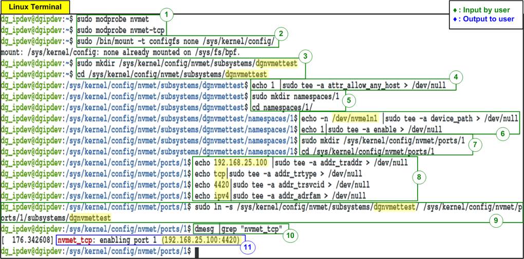
Figure 3 Target Setting
1) Load the NVMe/TCP target module by running the following command.

2) Mount the kernel user configuration filesystem to manage NVMe/TCP target settings.
![]()
3) Create an NVMe target subsystem and define the NVMe Qualified Name (NQN). The NQN must match the ‘TrgNQN’ setting in the NVMeTCP25G-IP demo. Assumed that the NQN is configured by “dgnvmettest”, use the following commands to navigate to the subsystem directory.

Note: While the ‘TrgNQN’ on the NVMeTCP25G-IP supports up to 256 characters, the demo system allows input up to 16 characters. Ensure the NQN length does not exceed this limit.
4) Set the attribute to allow any host to connect using the following command. This setting is suitable for testing but should be restricted in production environments. The NVMeTCP25G-IP allows configuration of the ‘Host NQN’ value.
![]()
5) Create a namespace for the subsystem and navigate to the new directory using following command.

6) Assign a local NVMe SSD to the system and enable it using the following command.

Note: Replace ‘nvme1n1’ with the correct device identifier for your SSD.
7) Create an NVMe target port to export the created subsystem and navigate to the appropriate directory using the following command.

8) Configure Ethernet parameters for the NVMe target port, including the following:
a) IP address = 192.168.25.100
b) Transport type = tcp
c) Port number = 4420
d) Address family = ipv4

Note: Ensure the IP address corresponds to the Ethernet port configured in Section 2.2 (Ethernet Interface Setting on Linux PC).
9) Create a symbolic link between the target port and the subsystem using the following command.

Note: The Target NQN (dgnvmettest) must match the value configured in step 3).
10) Verify that the target is correctly configured by inspecting the system messages using the following command.
![]()
11) If the configuration is successful, the system messages will display the target IP address and port number, as shown in Figure 4.
![]()
Figure 4 NVMe/TCP Target Setup Success Message
2.4 Removing NVMe/TCP Target Configuration on Linux PC
This section provides step-by-step instructions for removing the NVMe/TCP target configuration on Linux PC after completing the tests, as shown in Figure 5.
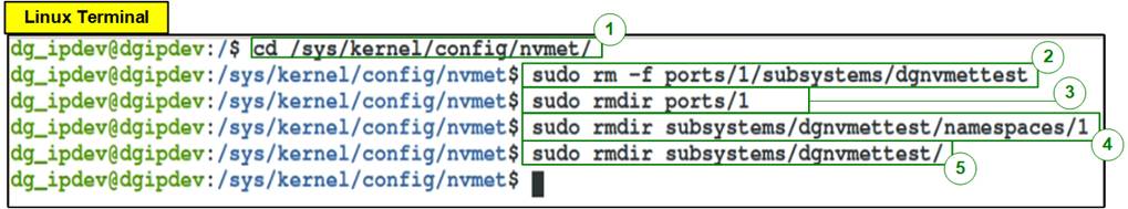
Figure 5 Remove NVMe/TCP Target
1) Navigate to the directory where the NVMe/TCP configurations are stored.
![]()
2) Delete the directory corresponding to the target port to remove its connections.

3) Remove subsystems linked to the NVMe SSD.

By following these steps, you can ensure the NVMe/TCP target configuration is properly removed, and the NVMe SSD is returned to its standard operational state for regular PC usage.
3 Test operation
Upon the completion of both the Linux PC and FPGA setups, the FPGA console displays a welcome screen, indicating readiness for operations. This is confirmed by the display of the IP name, IP version number, and the status of the Ethernet connection.

Figure 6 Message after System Boot-up
· IP Details: The console displays the name and version of the NVMeTCP25G-IP. If the Ethernet MAC IP Core from Design Gateway is used, its version will also be shown.
· Ethernet Status: The status of the Ethernet connection on the FPGA is displayed. If the Ethernet link fails to establish, an error message prompting a check of the Ethernet cable appears.

Figure 7 Error Message when Ethernet Connection Down
Once the Ethernet link is successfully established, the main menu will appear. This menu provides several options, each corresponding to different stages of the test process. Initially, only the relevant menu items are available, ensuring that the correct sequence of operations is followed. The first action after boot-up is selecting Menu [0] to configure the network parameters.
3.1 Set Network Parameter
Select option ‘0’ from the main menu to configure the IP parameters. This step is required to set up or update the network settings for communication between the host and target. Initially, the current parameters are shown on the console. The user can either enter ‘x’ to keep the existing setting or enter any other key to modify the parameters. If an invalid value is entered while setting a parameter, the existing value of that parameter remains unchanged. Below is a list of input parameters.
1) Target NVMe Qualified Name (NQN): Identifies the target SSD. Accepts up to 16 characters and the default is “dgnvmettest”.
2) Host MAC Address: Requires a 12-digit hexadecimal value for the host with the prefix “0x”. The default value is 0x000102030405.
3) Host IP Address: Input as four decimal numbers separated by dots. Each segment ranges from 0-255. The value is assigned to be the IP address of the host. The default is 192.168.25.44.
4) Host Port Number: Inputs the Admin and IO port numbers for the host, with valid inputs ranging from 0 to 65535. The defaults are 40000 (Admin) and 40001 (IO).
5) Target MAC Address Mode: Press ‘y’ to switch to Fixed-MAC mode instead of using ARP mode (which retrieves the MAC address via ARP). The default mode is ARP.
6) Target MAC Address: Requires a 12-digit hexadecimal value prefixed with “0x” for the target. The default is 0x101112131415.
Note: This parameter is available only if the Target MAC Address mode is set to Fixed-MAC, as shown in Figure 9.
7) Target IP Address: Follows the same format as the Host IP address. This value is assigned to be the IP address of the target. The default value is 192.168.25.100.
Once all parameters are set, they are displayed for user confirmation. If the user confirms the settings by entering ‘y’, the parameters are configured on the NVMeTCP25G-IP. A confirmation message, “IP parameters are set”, is shown upon successful configuration
The main menu reappears with offering the ‘Connect’ command as the next step, as detailed in Figure 8.
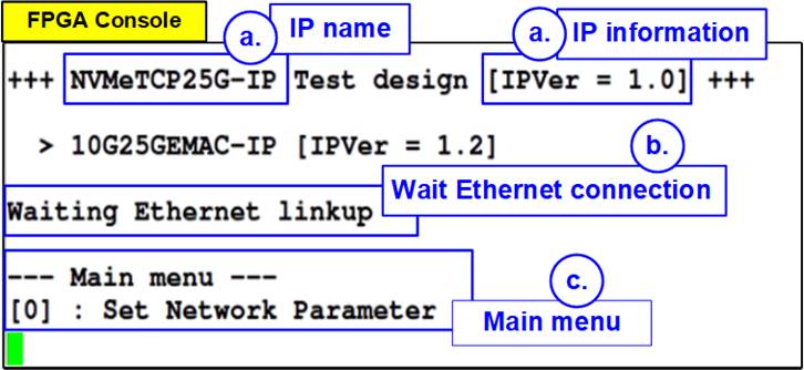
Figure 8 Set Network Parameter Result (ARP Mode)
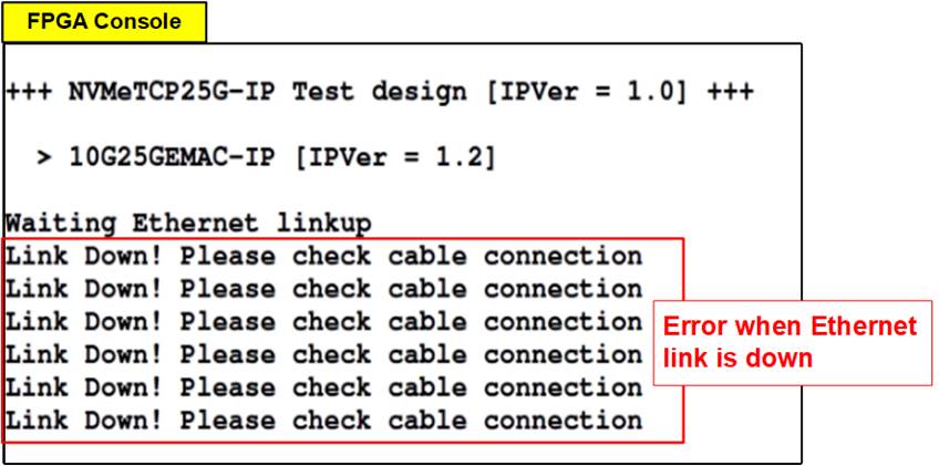
Figure 9 Set Network Parameter Result (Fixed-MAC Mode)
3.2 Connect
Select option ‘1’ from the main menu to establish a connection between the host and the target.
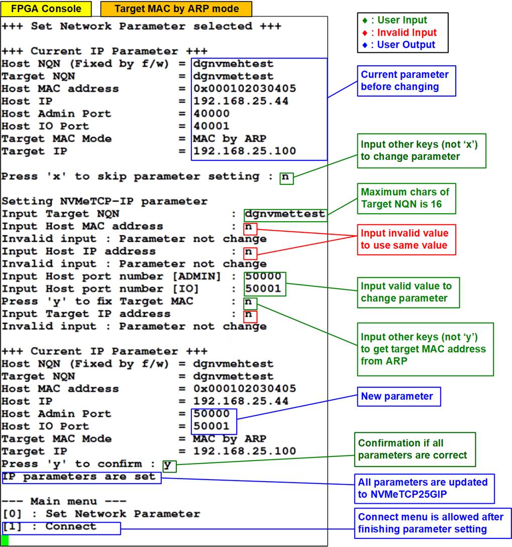
Figure 10 Console Result when Connect Succeeded
The NVMeTCP25G-IP (host) established a TCP/IP connection using the network parameters configured in Section 3.1 (Set Network Parameter). Following successful TCP/IP setup, the NVMe/TCP connection is established using the specified Target NQN, ensuring that the host is correctly linked to the designated target NVMe SSD. Upon successfully connection, the console displays “Connect target successfully”, along with the capacity of the target NVMe SSD. The menu then updates to include options for Write, Read, and Disconnect commands, as illustrated in Figure 10.
If the connection process takes longer than expected, the waiting time will be updated and displayed every second. In cases where TCP/IP initialization fails or the host cannot connect to the target, the console displays error status and detailed error information. Additionally, the TestPin (Internal Test Pin of the IP) is displayed.
If an error occurs, the system must be reset before attempting a new test. This requirement is shown in both Figure 11 and Figure 12.
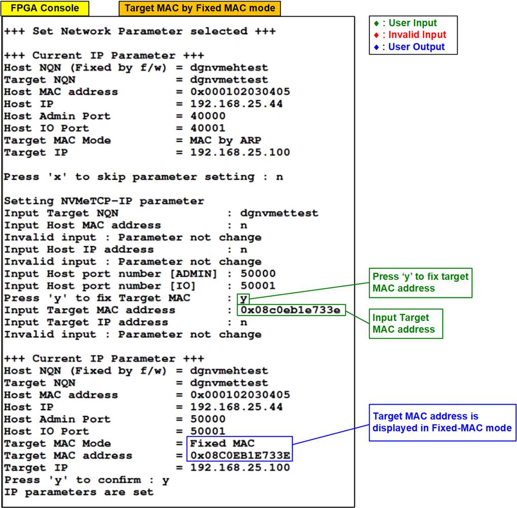
Figure 11 Console Result when TCP/IP Initialization Failed
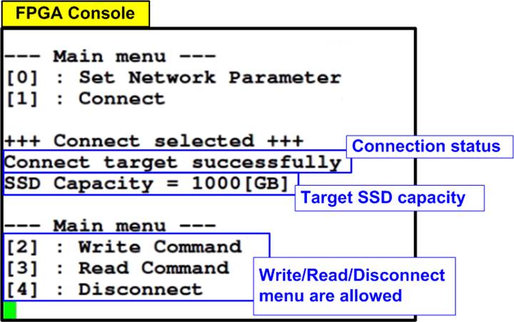
Figure 12 Console Result when Target Connection Failed
3.3 Write Command
Select option ‘2’ from the main menu to perform a write operation to the target NVMe SSD. This command tests the data transfer from host’s ability to send Write commands and pattern data over Ethernet, allowing data to be written to the target NVMe SSD.
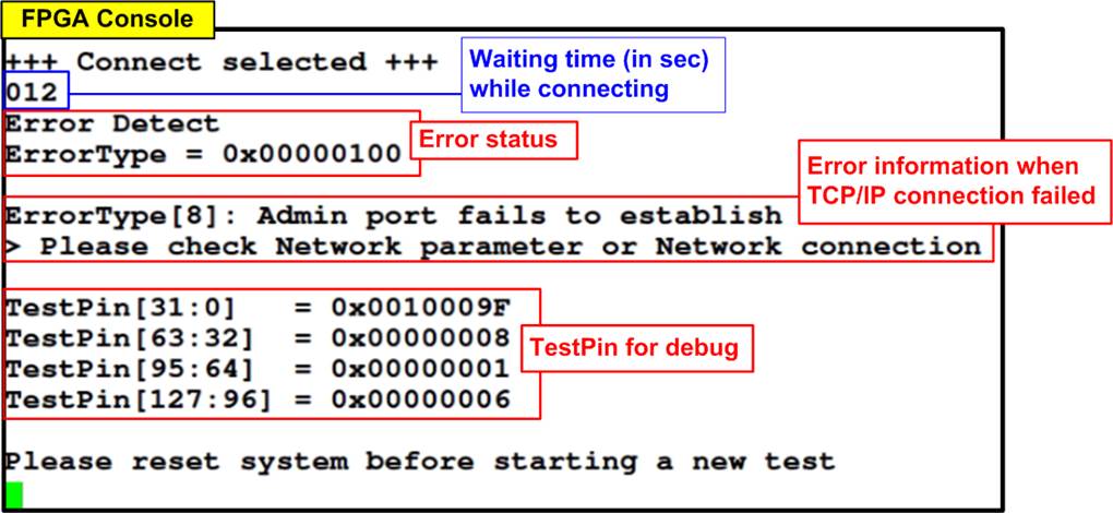
Figure 13 Test Result of Write Command
User inputs three parameters as follows.
1) Start Address: Input the start address where the write operation begins on the target NVMe SSD, specified in 512-byte units. Enter the address in decimal form or use the “0x” prefix for hexadecimal values. Ensure the address aligns to 4 KB (8 x 512 bytes), the fixed data length for each Write command.
2) Transfer Length: Input the total size to be written in 512-byte units. Like the start address, this can be entered in decimal or hexadecimal (with “0x” prefix) and must align to 4 KB.
3) Test pattern: Choose a data pattern for writing. Available options include 32-bit incremental, 32-bit decremental, all 0, all 1, and 32-bit LFSR counter.
Note: SSDs may exhibit optimal performance with the all-zeros pattern due to data compression algorithms inside the SSD controller.
Upon validating all inputs, the write process commences. The console displays the amount of data transferred every second to indicate the operation’s progress. Upon completion, the console displays the total size transferred, total time used, and test speed.
For the incremental, decremental, and LFSR patterns, each 4 KB data block starts with a unique 64-bit header. This header consists of a 48-bit address (in 512-byte units), followed by 16 bits set to zero. The remainder of the data block is filled with the chosen test pattern. Figure 14 and Figure 15 illustrate examples using the 32-bit incremental and LFSR patterns, respectively. The unique header is omitted when using all-zero or all-one patterns.
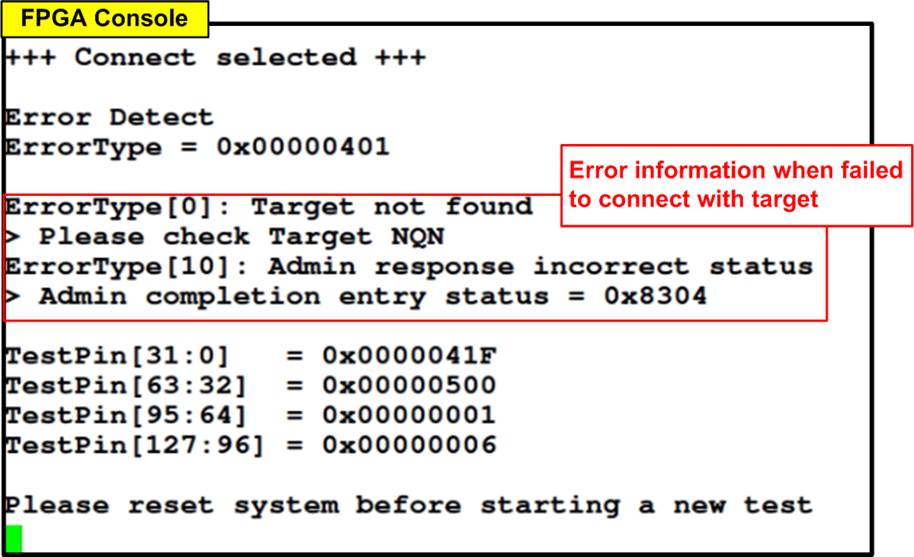
Figure 14 Example Test Data using Incremental Pattern
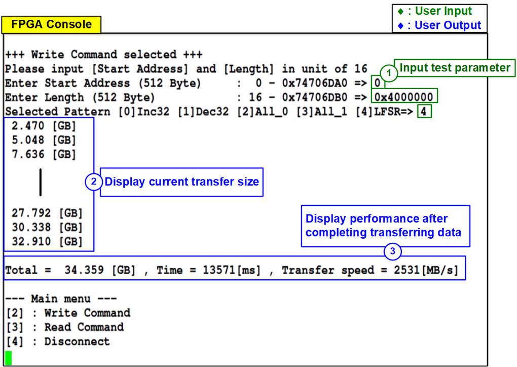
Figure 15 Example Test Data using LFSR Pattern
If any invalid inputs are detected, the console displays an “Invalid input” message, and the operation is cancelled, as depicted in Figure 16.
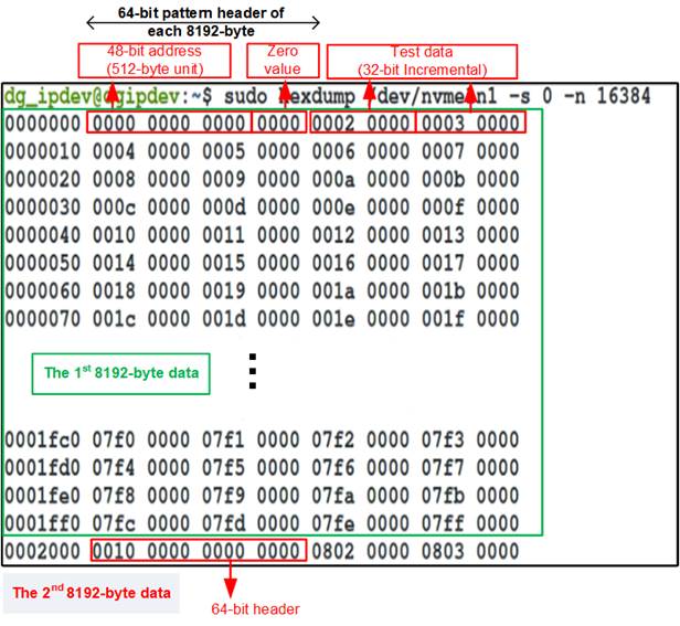
Figure 16 Error Message from Invalid Input
3.4 Read Command
Select option ‘3’ to initiate a Read operation from the target NVMe SSD. This menu facilitates the testing of read operations by sending a Read command over Ethernet. Following the command, the host awaits the data read from the target NVMe SSD.
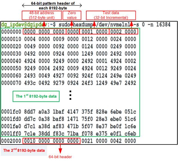
Figure 17 Test Result of Read Command using 1-MB Read Buffer Size
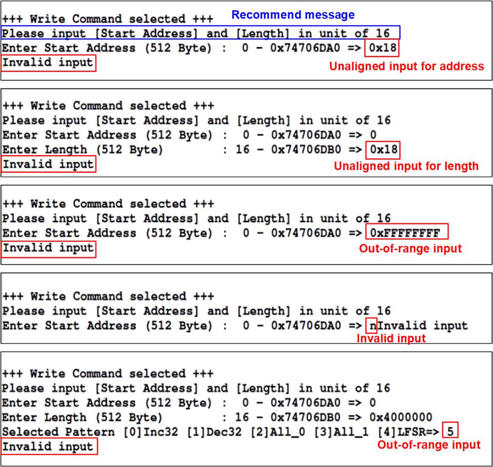
Figure 18 Test Result of Read Command using 64-KB Read Buffer Size
The user inputs three parameters as follows.
1) Start Address: Input the start address where the read operation begins on the target NVMe SSD, specified in 512-byte units. Enter the address in decimal form or use the “0x” prefix for hexadecimal values. Ensure the address aligns to 4 KB (8 x 512 bytes), the fixed data length for each Read command.
2) Transfer Length: Input the total size to be read in 512-byte units. Like the start address, this can be entered in decimal or hexadecimal (with “0x” prefix) and must align to 4 KB.
3) Test pattern: Choose a data pattern to verify the data received from the target. Ensure the test pattern matches the one used during the Write command. Options include 32-bit incremental, 32-bit decremental, all 0, all 1, and 32-bit LFSR counter.
Once all inputs are validated, the read process begins. The console displays the amount of data transferred every second to indicate the operation’s progress. Upon completion, the console displays the total size transferred, total time used, and test speed.
According to the NVMeTCP25G-IP specification, read performance may vary depending on the read buffer size. Larger read buffer sizes may enhance read performance, as shown in Figure 17 and Figure 18.
If data verification fails, the console will display an error message, showing the first mismatch in the data, including the error byte address, the expected value, and the actual value received (as shown in Figure 19).
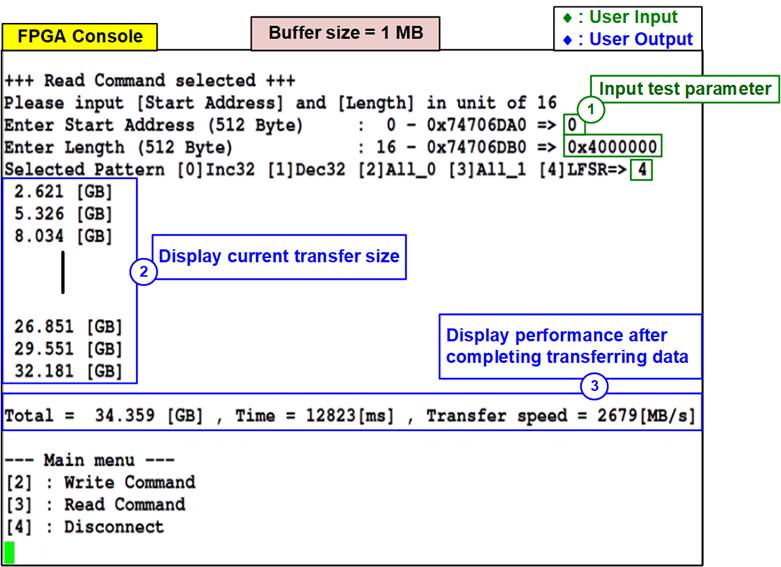
Figure 19 Test Result when Data Verification Failed
3.5 Disconnect Command
Select option ‘4’ to disconnect the host from the target. This menu terminates the connection between the NVMeTCP25G-IP (host) and the target, previously established in Section 3.2 (Connect Command). Upon selecting Disconnect, a confirmation prompt appears on the console. Press ‘y’ to proceed with the disconnection or any other key to cancel the operation.
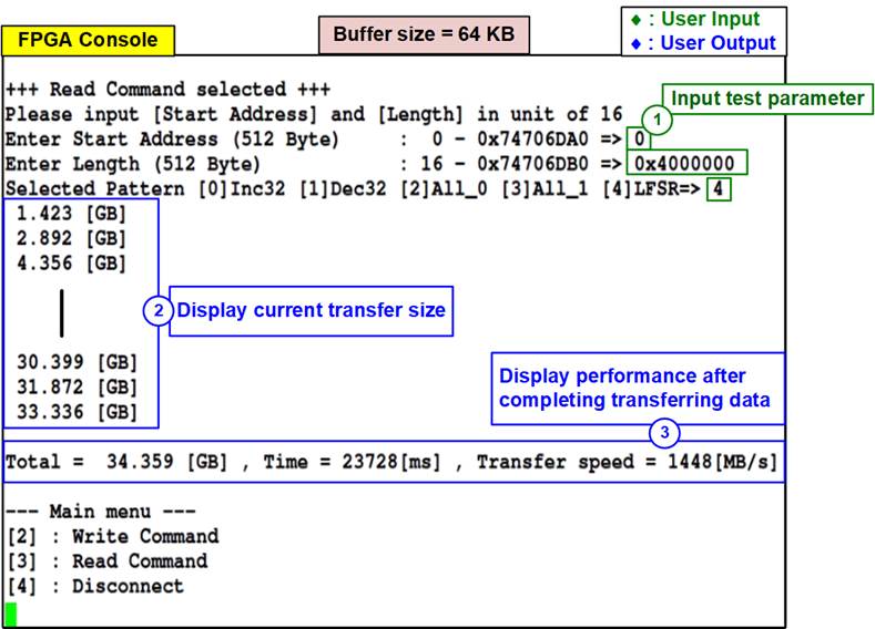
Figure 20 Result of Disconnect Command
Following a successful disconnection, the message “Disconnect target successful” will be displayed on the console. This indicates that both the TCP/IP and NVMe/TCP connections have been properly terminated.
After disconnecting, the user has the following options:
· Reset network parameters: Use the ‘Set Network Parameter’ menu to adjust settings or configure a new target.
· Re-establish the connection: Use the ‘Connect’ command to reconnect with the same target.
Note: When re-connecting the host to the target, be aware of potential limitations on the target system, such as the duration of the TCP/IP “Time-Wait State” and whether “TCP Port Reuse” is enabled on the target side, which may affect re-establishment of the connection.
4 Revision History
|
Revision |
Date (D-M-Y) |
Description |
|
2.00 |
19-Sep-24 |
Update performance result using 4KB data block |
|
1.00 |
25-Mar-22 |
Initial version release |