QUIC10GC-IP Core Datasheet
· Open and close a secure connection

Core Facts |
|
|
Provided with Core |
|
|
Documentation |
User Guide, Design Guide |
|
Design File Formats |
Encrypted File |
|
Instantiation Templates |
VHDL |
|
Reference Designs & Application Notes |
Vivado Project, See Reference design manual |
|
Additional Items |
Demo on ZCU106 |
|
Support |
|
|
Support Provided by Design Gateway Co., Ltd. |
|
Design Gateway Co., Ltd
E-mail: ip-sales@design-gateway.com
URL: design-gateway.com
Features
· 10Gbps QUIC engine conforming to RFC9000.
· Supports the Client-side QUIC operation.
· Supports TLS1.3 cipher suite:
· TLS_AES_128_GCM_SHA256
· Key exchange: X25519
· Derive key: HKDF with SHA256
· Encryption/decryption: AES128GCM
· Certificate type: RSA2048
· Signature algorithm: rsa_pss_rsae_sha256
· Supports four streams (StreamIDs #0-3) compliant with the QUIC standard.
· Includes integrated UDP/IP and ARP protocol controllers.
· Requires an IP core clock frequency of 200 MHz as a minimum recommended frequency.
· Supports unaligned AXI4 protocol for user data interface.
· Utilizes a ring buffer technique for user memory management interface.
· Supports 32-bit MAC interface using AXI4-Stream protocol, operating at 322.266 MHz.
· Customized service options:
· Increase the number of supported streams.
· Increase user buffer size.
· Extend certificate size.
· Enable 0-RTT session resumption.
Table 1: Example Implementation Statistics
|
Family |
Example Device |
Fmax (MHz) |
CLB Regs |
CLB LUTs |
CLB1 |
IOB |
BRAMTile |
Design Tools |
|
Zynq-Ultrascale+ |
xczu7ev-ffvc1156-2-e |
225 |
21942 |
47584 |
8812 |
- |
121.5 |
Vivado2022.1 |
Notes:
1) The actual logic resource depends on the percentage of unrelated logic.
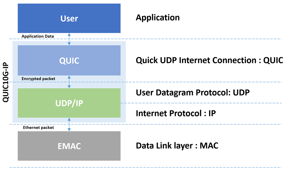
Figure 1: The QUIC protocol architecture
General Description
QUIC is a cryptographic transport protocol designed to provide a secure and efficient connection between a client and server over the network. Before the development of the QUIC protocol, the TLS protocol was widely used for secure communication, but it depends on the transport protocol, named TCP/IP, for the connection-oriented and reliable data transmission. This dependency limits the performance of the TLS protocol. For this reason, the QUIC protocol was designed and later approved as a standard to provide a secure data transfer protocol and to address the limitations faced by TLS.
The fact that QUIC protocol spans multiple layers in the OSI model offers the flexibility and control over how it manages its own data flow. This allows QUIC protocol to implement its transport specification to tackle network problems in actual systems, as well as to develop its own data flow structure to support the need for multiple stream connections. These advantages of the QUIC protocol are just examples of what it offers to overcome the limitations of TLS.
Although several network applications these days still use the TLS protocol for secure data transfer, it is becoming more common, at the time of writing this document, to find the use of the QUIC protocol in web browsing, DNS, and other applications. For example, the QUIC protocol is on by default in Chrome browser, and many other major companies, such as Apple and Facebook, have adopted QUIC in their applications.
Our QUIC Client 10Gbps IP Core (QUIC10GC-IP) is specifically engineered to manage the TLS1.3 handshake for a client, encrypt outgoing payload data, decrypt incoming payload data and handle QUIC transport tasks, effectively covering both QUIC and UDP/IP layers, as illustrated in Figure 1. Prior to transferring payload data using the QUIC protocol, a handshake process is initiated to establish a secure connection. During this phase, cryptographic keys are exchanged and generated to ensure the data confidentiality, and the QUIC client also validates the server's signature and certificate to ensure authenticity. The QUIC10GC-IP allows data transmission only after a successful handshake has created a secure channel between the two parties.
The QUIC Protocol Version 1 and
several technical terms mentioned in this document adheres to the standards
defined by RFC9000. For more information, please refer to the RFC9000 document. For
details on TLS Protocol Version 1.3, please refer to the RFC8446 document.
Application Example
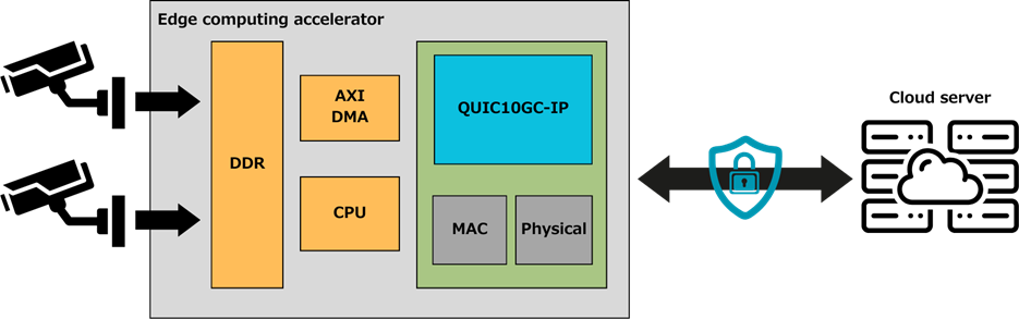
Figure 2: QUIC10GC-IP in an edge computing accelerator application
In the application above, the QUIC10GC-IP is employed in an edge device that captures real-time video and sends it over the network to a server for analysis. This use case highlights the critical need for secure data transmission, especially when dealing with confidential information. By using the QUIC10GC-IP, data is encrypted before transmission, significantly reducing the risk of unauthorized access. Even in the case of a data breach, it may take a long time* for those who have it to crack the encryption.
The QUIC10GC-IP's ability to integrate into a system with an operating system (OS) is illustrated in Figure 2. The IP can access the main memory via the AXI4 protocol, connecting to an AXI interconnect that facilitates memory access. This integration allows applications on the OS to interact with the IP by simply reading and writing data to memory. The IP then directly accesses this memory using DMA techniques, providing a secure and efficient data transfer mechanism. This setup is particularly useful for applications requiring an OS for complex tasks while needing the security provided by the QUIC protocol to protect data during network transmission.
Note:
* If a brute force attack were attempted on AES-128 encryption, it would take an estimated billion years to crack (reference: appsealing.com/aes-128-encryption).
Functional Description
Figure 3 illustrates QUIC10GC-IP block diagram and its interface signals. Users can control and transfer data with QUIC10GC-IP via the user interface signals as described in Table 2.
· MAC Interfaces: The interfaces that connect to the lower layer, namely MAC Tx I/F and MAC Rx I/F, run at a clock frequency of 322.266 MHz. These interfaces are used to transfer network packets with the MAC layer.
· Core Interfaces: The remaining interfaces run at the IP core clock frequency, called QUICClk, which is recommended to be set greater than 200 MHz for optimized performance.
To set parameters and start the IP, the user uses the control groups – Network parameters group for setting essential network parameters, Connection parameters for setting QUIC parameters and some network parameters, and Connection Control I/F for controlling and monitoring the QUIC connection. To transfer QUIC data, the user manages send and receive data through User Tx/Rx Memory I/F, and IP is then responsible for handling user data transfers through AXI4 Write/Read Channels. Additionally, the user can also monitor QUIC Rx information frames through User Rx Info group and can access handshake information in details through QUIC handshake info group. However, these optional interfaces enable advanced monitoring and debugging capabilities but can be ignored if the user only needs a straightforward data transfer channel through the QUIC10GC-IP.
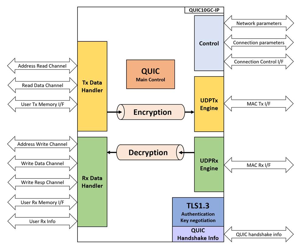
Figure 3: QUIC10GC-IP block
diagram
Table 2: Core Parameters
|
Parameter name |
Value |
Description |
|
ClockPerUS |
100-1000 |
Setting number of cycles per micro-second. This value is a requirement for using the IP. |
Table 3: QUIC10GC-IP Interface signals
|
Signal name |
Dir |
Description |
|
RstB |
In |
IP core system reset. Active low. |
|
QUICClk |
In |
IP core system clock. |
|
MacTxClk |
In |
Clock signal which is synchronous to Tx MAC interface for running with low-latency 10G MAC, at the frequency of 322.266 MHz. |
|
MacRxClk |
In |
Clock signal which is synchronous to Rx MAC interface for running with low-latency 10G MAC, at the frequency of 322.266 MHz. |
|
version[31:0] |
Out |
32-bit version number of QUIC10GC. |
|
Network parameters |
||
|
NetworkSet |
In |
User asserts to ‘1’ when network parameters are valid. |
|
SrcMacAddr[47:0] |
In |
MAC address of QUIC IP. |
|
SrcIPAddr[31:0] |
In |
IP address of QUIC IP. |
|
GatewayIPAddr[31:0] |
In |
IP address of Gateway. This value must be set to 0.0.0.0 if there is no gateway in the system. |
|
Connection Parameters |
||
|
DstIPAddr[31:0] |
In |
IP address of the target device. |
|
SrcUDPPort[15:0] |
In |
UDP source port of QUIC IP. |
|
DstUDPPort[15:0] |
In |
UDP target port of QUIC IP. |
|
QUICALPNLen[4:0] |
In |
User sets ALPN string length. Maximum value is 16 ("10000"). Values exceeding this cause a QUIC error. |
|
QUICALPNStr[127:0] |
In |
User sets ALPN string value. |
|
Connection Control interface |
||
|
ConnOn |
In |
User sets connection status. ‘1’: connection is active, ‘0’: no connection. |
|
QUICConnOnBusy |
Out |
Specifies the busy status of connection operation. Active after ConnOn is set to ‘1’ until operation is done. ConnOn will be ignored while QUICConnOnBusy is ‘1’. |
|
QUICHandshakeBusy |
Out |
Specifies the busy status of handshake operation. |
|
Out |
Specifies the busy status of data transmit operation. |
|
|
QUICRxTrnsBusy |
Out |
Specifies the busy status of data receive operation. |
|
QUICAlertInt |
Out |
Alert Interrupt. Asserted to ‘1’ for a cycle when an alert is detected. |
|
QUICAlertCode[15:0] |
Out |
Indicates normal or alert conditions. QUICAlertCode[15]: ‘1’ alert from server, ‘0’ alert from IP. QUICAlertCode[14:0]: Alert description. |
|
AXI4 Address Read Channel |
||
|
QUICTxArReady |
In |
Indicates that the slave is ready to accept the address read command. |
|
QUICTxArValid |
Out |
Indicates that the address and control information is valid. |
|
QUICTxArAddr[63:0] |
Out |
Carries the address for the read transaction. |
|
QUICTxArLen[7:0] |
Out |
Specifies the length of the data transaction (number of data transfers). |
|
AXI4 Read Data Channel |
||
|
QUICTxrReady |
Out |
Indicates that the master is ready to accept the read data. |
|
QUICTxrValid |
In |
Indicates that the read data is valid and can be read by the master. |
|
QUICTxrData[127:0] |
In |
Carries the read data from the slave to the master. |
|
QUICTxrStrb[15:0] |
In |
Indicates which bytes of the read data are valid (one bit per byte). |
|
QUICTxrLast |
In |
Indicates the last transfer in a burst transaction. |
|
AXI4 Address Write Channel |
||
|
QUICRxAwReady |
In |
Indicates that the slave is ready to accept the address write command. |
|
QUICRxAwValid |
Out |
Indicates that the address and control information is valid. |
|
QUICRxAwAddr[63:0] |
Out |
Carries the address for the write transaction. |
|
QUICRxAwLen[7:0] |
Out |
Specifies the length of the data transaction (number of data transfers). |
|
AXI4 Write Data Channel |
||
|
QUICRxwReady |
Out |
Indicates that the slave is ready to accept the write data. |
|
QUICRxwValid |
In |
Indicates that the write data is valid and can be written from the master to the slave. |
|
QUICRxwData[127:0] |
In |
Carries the write data from the master to the slave. |
|
QUICRxwStrb[15:0] |
In |
Indicates which bytes of the write data are valid (one bit per byte). |
|
QUICRxwLast |
In |
Indicates the last transfer in a burst transaction. |
|
AXI4 Write Response Channel |
||
|
QUICRxbReady |
Out |
Indicates that the master is ready to accept the write response. |
|
QUICRxbValid |
In |
Indicates that the write response is valid. |
|
User Tx Memory Management interface |
||
|
AppTxBaseAddr[63:0] |
In |
Base address for the application streams. |
|
AppTxWrFin0 |
In |
Write finish signal for StreamID0. |
|
AppTxWrAddr0[17:0] |
In |
Write address for StreamID0. |
|
AppTxRdAddr0[17:0] |
Out |
Read address for StreamID0. |
|
AppTxWrFin1 |
In |
Write finish signal for StreamID1. |
|
AppTxWrAddr1[17:0] |
In |
Write address for StreamID1. |
|
AppTxRdAddr1[17:0] |
Out |
Read address for StreamID1. |
|
AppTxWrFin2 |
In |
Write finish signal for StreamID2. |
|
AppTxWrAddr2[17:0] |
In |
Write address for StreamID2. |
|
AppTxRdAddr2[17:0] |
Out |
Read address for StreamID2. |
|
AppTxWrFin3 |
In |
Reserved. |
|
AppTxWrAddr3[17:0] |
In |
Reserved. |
|
AppTxRdAddr3[17:0] |
Out |
Reserved. |
|
User Rx Memory Management interface |
||
|
AppRxBaseAddr[63:0] |
In |
Base address for the application streams. |
|
AppRxWrFin0 |
Out |
Write finish signal for StreamID0. |
|
AppRxWrAddr0[17:0] |
Out |
Write address for StreamID0. |
|
AppRxRdAddr0[17:0] |
In |
Read address for StreamID0. |
|
AppRxWrFin1 |
Out |
Write finish signal for StreamID1. |
|
AppRxWrAddr1[17:0] |
Out |
Write address for StreamID1. |
|
AppRxRdAddr1[17:0] |
In |
Read address for StreamID1. |
|
AppRxWrFin2 |
Out |
Reserved. |
|
AppRxWrAddr2[17:0] |
Out |
Reserved. |
|
AppRxRdAddr2[17:0] |
In |
Reserved. |
|
AppRxWrFin3 |
Out |
Write finish signal for StreamID3. |
|
AppRxWrAddr3[17:0] |
Out |
Write address for StreamID3. |
|
AppRxRdAddr3[17:0] |
In |
Read address for StreamID3. |
|
User Rx information |
||
|
QUICRxInfoValid |
Out |
Indicates that the Rx information is valid. |
|
QUICRxInfoType |
Out |
Type of the Rx information. |
|
QUICRxInfoID |
Out |
StreamID associated with the Rx information. |
|
QUICRxInfoD0 |
Out |
Data field 0 of the Rx information. |
|
QUICRxInfoD1 |
Out |
Data field 1 of the Rx information. |
|
QUIC handshake information* |
||
|
QUICCertData[15:0] |
Out |
Server certificate information. Valid when QUICCertValid=‘1’. |
|
QUICCertValid |
Out |
Asserted to ‘1’ when QUICCertData is valid. |
|
QUICCertByteEn[1:0] |
Out |
Byte enable of QUICCertData. Valid when QUICCertValid=‘1’. The signal can be equal to two values: "01" or "11", when QUICCertData[7:0] or QUICCertData[15:0] is valid, respectively. |
|
QUICCertLast |
Out |
Specifies the last word of QUICCertData. |
|
QUICKeyValid |
Out |
Asserted to ‘1’ when key materials are valid. |
|
Random[255:0] |
Out |
256-bit Random number in ClientHello. Valid when QUICKeyValid is asserted to ‘1’. |
|
CTS[255:0] |
Out |
Client Traffic Secret is key material Valid when QUICKeyValid is asserted. |
|
STS[255:0] |
Out |
Server Traffic Secret is key material Valid when QUICKeyValid is asserted. |
|
MAC Tx Interface (Synchronous to TxClk) |
||
|
MACTxReady |
In |
Asserted to ‘1’ when MACTxData is being accepted. |
|
MACTxValid |
Out |
Asserted to ‘1’ when MACTxData is valid. |
|
MACTxData[31:0] |
Out |
Transmitted data of the IP to the Ethernet MAC. It is valid when ‘MACTxValid’ is set to ‘1’. |
|
MACTxByteEn[3:0] |
Out |
Byte enable of MACTxData. Valid when MACTxValid=‘1’. During packet transmission, this signal is equal to “1111” for enabling all 32-bit data except the final data of the packet which can be equal to four values: “0001”, “0011”, “0111”, or “1111” when MACTxData[7:0], [15:0], [23:0], or [31:0] is valid respectively. |
|
MACTxSOP |
Out |
Asserted to ‘1’ with the first data of the packet on MACTxData. Valid when MACTxValid is asserted to ‘1’. |
|
MACTxEOP |
Out |
Asserted to ‘1’ with the final data of the packet on MACTxData. Valid when MACTxValid is asserted to ‘1’. |
|
MAC Rx Interface (Synchronous to RxClk) |
||
|
MACRxValid |
In |
Asserts to ‘1’ to transfer MACRxData. |
|
MACRxData[31:0] |
In |
Received data from the Ethernet MAC. It is valid when MACRxValid is set to ‘1’. |
|
MACRxByteEn[3:0] |
In |
Byte enable of MACRxData. Valid when MACRxValid=‘1’. During packet transmission, this signal is equal to “1111” for enabling all 32-bit data except the final data of the packet which0 can be equal to four values: “0001”, “0011”, “0111”, or “1111” when MACRxData[7:0], [15:0], [23:0], or [31:0] is valid respectively. |
|
MACRxEOP |
In |
Asserts to ‘1’ to indicate that this is the last data. |
|
MACRxError |
In |
Asserts to ‘1’ to indicate that this frame contains an error. This signal is valid when the last data is transferred, as indicated by MACRxEOP=‘1’. |
* QUIC handshake information is optional signals that user can access handshake information in details. User can ignore these signals and implement QUIC10GC-IP as a channel to pass through payload.
· Set parameters
Users must configure network parameters for the QUIC10GC-IP on the IP (Source) side by asserting NetworkSet to '1' while QUICConnOnBusy is '0'. During this operation, the SrcMacAddr[47:0], SrcIPAddr[31:0], and GatewayIPAddr[31:0] parameters must be valid. These parameters will remain unchanged for every connection until the user sets new parameters.
For each connection, users can update the DstIPaddr[31:0], DstUDPPort[15:0], and SrcUDPPort[15:0] values, which must be valid when the user asserts QUICConnOn to '1' while QUICConnOnBusy is '0'.
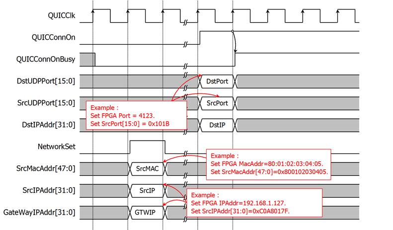
Figure 4: Example of setting network parameters
For ALPN (Application-Layer Protocol Negotiation), the ClientHello message includes an extension that informs the server about the application layer protocol to be used over the secure connection. Users can change the ALPN setting for every connection. When the user asserts QUICConnOn to '1' while QUICConnOnBusy is '0', both ALPNLength[4:0] and ALPNString[127:0] must be valid and will be used as ALPN information. To exclude this ALPN field from the ClientHello message, the user can set ALPNLength[4:0] to 0.
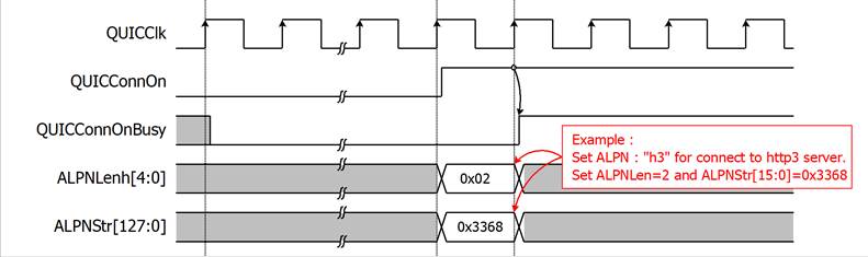
Figure 5: Example of setting an ALPN value to the QUIC10GC-IP
The QUIC10GC-IP connects to a network system by interfacing with a device's MAC address, which is necessary for sending and receiving network packets. This is achieved through an ARP (Address Resolution Protocol) handler integrated into the IP. The ARP handler operates either during the network parameter setup process or at the start of a new QUIC connection.
§ Set network parameters
When the NetworkSet signal is set to ‘1’, an internal controller within the IP initializes a scan of the value of the gateway address (GatewayIPAddr). If the GatewayIPAddr holds a non-zero value (i.e., not 0.0.0.0), the ARP protocol handler sends an ARP request packet to the gateway over the connected network. It then waits for an ARP reply from the gateway, as depicted in the timing diagram in Figure 6.
If an ARP reply is not received or is missing, the ARP handler will retransmit the request packet up to ten times. If no ARP reply is received after these attempts, the IP determines that it cannot connect to the gateway, and consequently, a QUIC connection through the gateway will not be possible.
It is important to mention that during this ARP process, the IP will not initiate any QUIC connections. Only after the ARP process is completed, the IP will proceed to operate the requested QUIC connection. This ensures that the necessary network parameters are correctly configured before attempting any data transmission.
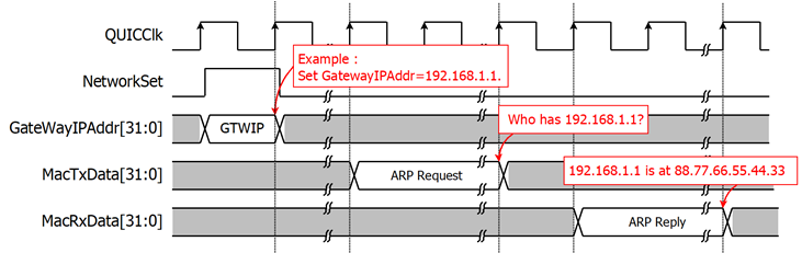
Figure 6 ARP process for connecting to a Gateway
§ Open a connection
When a new connection is requested, as will be described in the next topic, the ARP protocol handler sends an ARP request packet to the target device specified by the DstIPAddr signal. Similarly, it then waits for an ARP reply packet from the target device to complete this process, as shown in Figure 7.
During a QUIC connection, the IP first opts for the MAC address of the target device. If the first option is not available, meaning the IP did not receive an ARP reply packet from the target device, it uses the MAC address of the Gateway. If this option is also not available, the IP returns an alert code to the user.
For the next QUIC connection with the same destination address, the IP will not run this ARP process if the MAC address of the target device is already obtained from the previous connection. This reduces the waiting time for a connection.
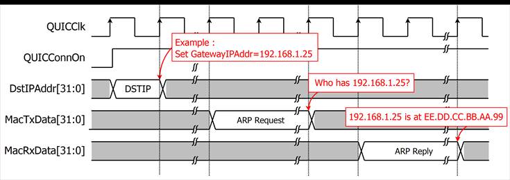
Figure 7 ARP process for
connecting to a target device
· Open and close a secure connection
The QUIC10GC-IP is designed to handle the full handshake process with a supported cipher suite, as well as encrypt and decrypt data over the network. Users can open a secure connection by asserting QUICConnOn to ‘1’ while QUICConnOnBusy is '0'. As shown in Figure 5, after QUICConnOn is asserted to ‘1’, QUICConnOnBusy is asserted to ‘1’ in the next cycle, and the QUIC10GC-IP begins the handshake operation, indicating by the fact that QUICHandshakeBusy is asserted to ‘1’. It is important to note that during this phase, data transmission is not permitted and also, the 0-RTT feature is not supported.
However, before the handshake process is finished (i.e., QUICHandshakeBusy is de-asserted to ‘0’), users are allowed to prepare TxData in the Tx user buffer. Once the handshake process is complete and data is available, the QUIC10GC-IP transitions to the data transfer phase. QUICTxTrnsBusy is asserted to ‘1’ when the Tx user buffer is not empty and is cleared when the TxData has been fully acknowledged by the server. When the server sends data to the QUIC10GC-IP, QUICRxTrnsBusy is asserted to ‘1’. QUICRxTrnsBusy is cleared when the received data is written to the Rx user buffer.
Users can close the connection only when QUICHandshakeBusy, QUICTxTrnsBusy, and QUICRxTrnsBusy are all not asserted to ‘1’. If users attempt to close the connection when any of these signals are asserted, the QUIC10GC-IP will return an ABNORMAL_CLOSE_ERROR.
During the connection, if an error occurs, the IP sends an alert code through the QUICAlertCode signal by asserting QUICAlertInt. After this, users should clear the QUICConnOn to ‘0’ before being able to create a new connection. More details about the alert codes can be found in the Alert handling section.
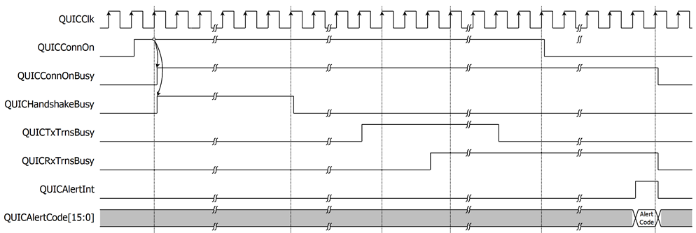
Figure 8: Example of opening and closing a connection
· Handshake process
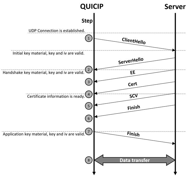
Figure 9: Handshake process
Figure 9 shows the main flow of the QUIC full handshake process. After the UDP connection is established, the QUIC10GC-IP, acting as a client, generates a ClientHello message. This message includes the supported cipher suite, which is TLS_AES_128_GCM_SHA256, the client’s ephemeral X25519 public key to the server and a 256-bit random number for each connection. The QUIC10GC-IP provides this random number via Random[255:0], which is valid when QUICKeyValid is asserted to ‘1’, as shown in Figure 11. Additionally, the QUIC10GC-IP generates a random connection ID used for identifying the connection. The QUIC10GC-IP uses random connection ID to generate the key materials for encryption and decryption of data. For the QUIC10GC-IP, the supported key derivation function is the Hash-based Key Derivation Function (HKDF) with SHA256.
The server responds by sending a ServerHello message, including the server’s ephemeral X25519 public key. When the QUIC10GC-IP receives the ServerHello message, it uses the server’s public key to compute the shared key using X25519. This shared key is then passed to a key derivation function to generate the key materials for encryption and decryption.
The QUIC10GC-IP uses HKDF-SHA256 to generate two key materials: the Client Traffic Secret (CTS) and the Server Traffic Secret (STS). CTS is used to derive the client traffic key and Initialization Vector (IV) to encrypt handshake messages sent by the client, while STS is used to derive the server traffic key and IV to decrypt handshake messages sent by the server. Users can access CTS and STS when QUICKeyValid is asserted to ‘1’.
The QUIC10GC-IP supports the verification of ServerCertificateVerify, which uses an RSA2048-PSS with SHA256 signature, and it returns the certificate information to the user. The maximum size of the certificate is 8 kB. The certificate data is valid when QUICCertValid is asserted. The QUICCertData[15:0] holds the certificate information, and QUICCertByteEn[1:0] indicates which byte within QUICCertData[15:0] is valid.
As shown in Figure 10, a 963-byte certificate is delivered. In this example, the last QUICCertData (C482) is valid for only 1 byte, with QUICCertByteEn[1:0] set to “01”. The signals QUICCertData[15:0], QUICCertValid, and QUICCertByteEn[1:0] can be used to write the certificate data to a buffer (such as FIFO or RAM). The QUICCertLast signal indicates the last cycle of QUICCertData. When QUICCertLast is asserted to '1', it signals that the server certificate information for Certificate Validity Verification is complete and ready for the user.
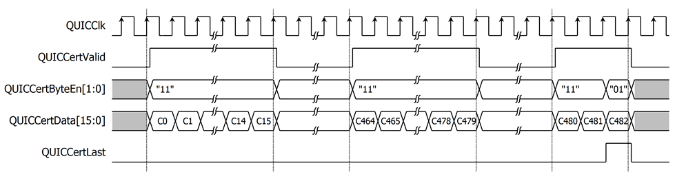
Figure 10: Example of a timing diagram for 963-byte certification information
After sending the client’s finished message, the QUIC10GC-IP regenerates key materials, specifically the CTS and STS, to derive the key and IV for application data. During this key derivation process, QUICKeyValid is de-asserted to ‘0’. Once the key derivation is completed, QUICKeyValid is asserted to ‘1’ to indicate that the random number, CTS and STS are valid, as depicted in Figure 11.
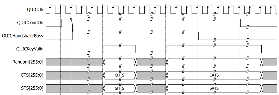
Figure 11: Example of controlling signals in handshake process timing diagram
· User Tx interface
The QUIC10GC-IP provides the support of four stream connections. Before using QUIC10GC-IP, users are required to allocate 1024KB of memory starting from AppTxBaseAddr[63:0], which the IP will use as a transmit buffer. This memory is divided into four blocks of 256KB, each designated for StreamID0, StreamID1, StreamID2, and StreamID3, respectively, as illustrated in Figure 12.
According to the QUIC protocol, StreamID0 and StreamID2 are client-initiated streams, while StreamID1 and StreamID3 are server-initiated streams. So StreamID0 and StreamID2 can be opened by the client sending data first, and StreamID1 and StreamID3 can be opened by the server sending data first. Therefore, users can use StreamID0 and StreamID2 to transmit data immediately after the handshake is complete. However, StreamID1 can only be used after the server has initiated it. Moreover, StreamID3 is a unidirectional stream, reserved for receive-only data, and cannot be used to transmit data.
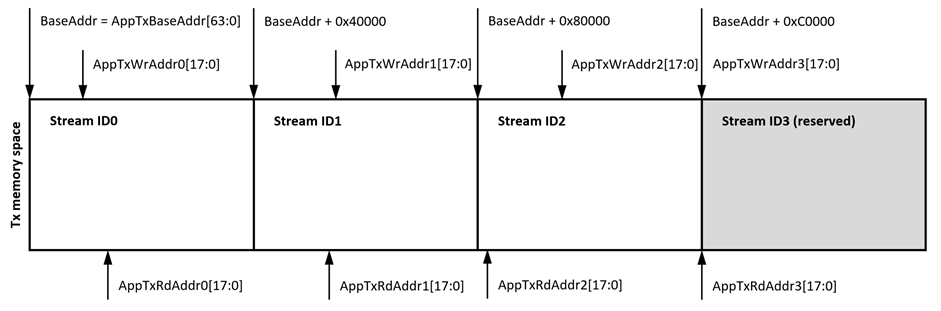
Figure 12: Transmit memory structure
Each block of memory in the transmit buffer functions as a circular buffer. This means that the buffer uses a write pointer (WrPtr) and a read pointer (RdPtr) to manage the flow of data. The WrPtr indicates the byte address to which data will be written, while the RdPtr indicates the byte address from which data will be read. The difference between these pointers shows the position of available data.
In Figure 13, three examples illustrate how to use the circular buffer in context. Figure 13a shows an empty buffer, with both pointers at the same address, at address 1. Figure 13b depicts data written from address 1 to 5, with WrPtr at address 6, indicating 5 bytes of available data from address 1 to 5, while RdPtr remains unchanged. Figure 13c demonstrates a full buffer scenario, where WrPtr is at address 3 and RdPtr has moved to address 4, preventing WrPtr from increasing further to avoid overwriting unread data. This also illustrates address 1 and 2 being reused, showing the use of the circular buffer concept.
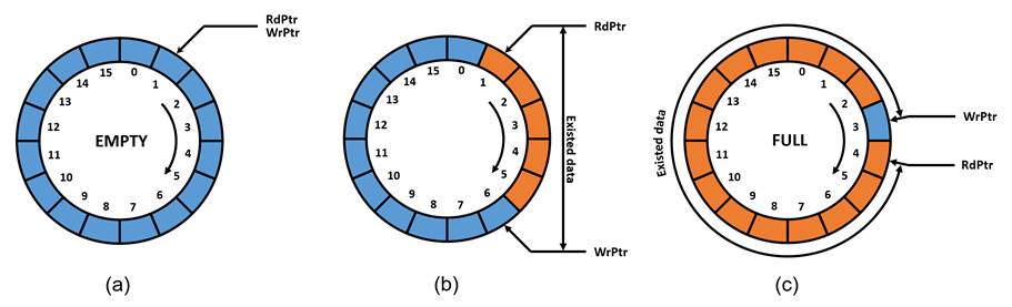
Figure 13: Example of the circular buffer concept
The transmit buffer uses AppTxWrAddrX[17:0] as the write pointer (WrPtr) and AppTxRdAddrX[17:0] as the read pointer (RdPtr), where ‘X’ represents the streamID. When a new connection is opened, AppTxRdAddrX[17:0] will be moved to the location of AppTxWrAddrX[17:0], ensuring that the transmit buffer is initially empty. The user can then prepare transmission data in the memory by updating AppTxWrAddrX[17:0], signaling to the QUIC10GC-IP that data is available in the transmit buffer for StreamID ‘X’. The QUIC10GC-IP reads this data via the AXI4 protocol, segments it into QUIC packets, encrypts, and sends it to the other endpoint. After reading the data, the QUIC10GC-IP moves AppTxRdAddrX[17:0] to the next byte address to be read, allowing the user to reuse that buffer section.
To close a stream in StreamID ‘X’, AppTxWrFinX needs to be set to ‘1’ along with the last valid address of AppTxRdAddrX[17:0] to ensure the remaining data up to this address is transmitted. After this, no additional data can be sent through StreamID ‘X’.
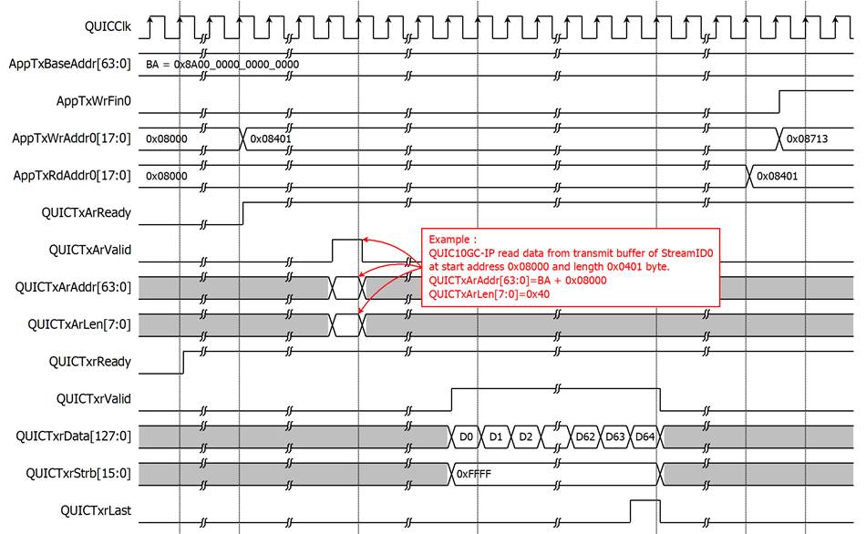
Figure 14: Example of reading data from the transmit buffer
To transfer data from memory, an AXI4 read controller is utilized in the User Tx data interface of our IP. The following constraints are applied:
· The burst attribute is set to INCR (ARBURST=0b00), indicating that the address for each transfer is incremented.
· Transfers can be unaligned, utilizing an unaligned start address and byte lane strobes.
· Single AXI4 transactions are applied.
· ARSIZE is set to 0b100, indicating 16 bytes per transfer.
· ARLEN is not fixed to 2, 4, 8, or 16.
· Maximum transaction bytes are capped at 4096 bytes per transaction.
· The address for each transfer is guaranteed to always be within a memory boundary.
· RRESP is not presented and assumed to be 0b000 (OKAY).
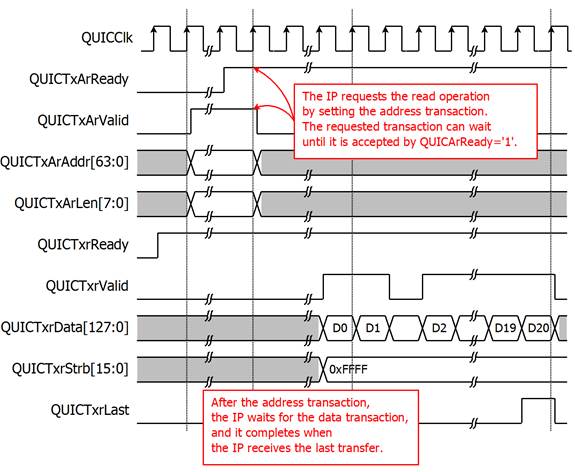
Figure 15 AXI4 read operation for the User Tx data interface
The example presents the sequence of the AXI4 read operation used by the IP to obtain the transmit data from the memory. The IP performs this operation in a single access only. It starts by sending the address transaction, asserting the QUICTxArValid to ‘1’ along with the valid values for QUICTxArAddr and QUICTxArLen. The first variable is the start address of the accessed memory, and the second is the transfer length in word units. For instance, Figure 15 shows the transfer of D0 – D20, hence, the transfer length is 0x14.
Once the address transaction is complete, the IP waits to receive the data transaction, which can be a burst or a single beat depending on the QUICTxArLen value. The read operation finishes when both QUICTxrValid and QUICTxrLast are asserted to ‘1’.
The IP supports the discontinuous transfers. When QUICTxArReady equals ‘0’, the IP holds the current valid values of the address transaction. Similarly, the data transaction can be paused by de-asserting QUICTxrValid to ‘0’. Additionally, QUICTxrReady is always asserted to ‘1’, indicating that the IP is ready to receive the data it requested.
For unaligned data transfer, the IP may request an unaligned start address, which is setting QUICTxArAddr[3:0] to any value other than 0x0. For example, when QUICTxArAddr[3:0]=0xA, the first data (D0) will be valid only in QUICTxrData[127:80], and the first value of QUICTxrStrb can be set to either 0xFFFF or 0xFC00.
· User Rx interface
Similar to the User Tx interface, the QUIC10GC-IP supports four stream connections. Another 1024KB of memory, starting from AppRxBaseAddr[63:0], must be reserved for the IP as a receive buffer, divided into four 256KB blocks for StreamID0, StreamID1, StreamID2, and StreamID3, respectively, as shown in Figure 16.
As specified by the QUIC protocol, the server can send data to StreamID1 and StreamID2 of the client without restrictions. However, the user must first send data through StreamID0 before the server can transmit any data through StreamID0. Additionally, StreamID2 is a unidirectional stream, reserved for a send-only stream and is not used as a receive buffer.
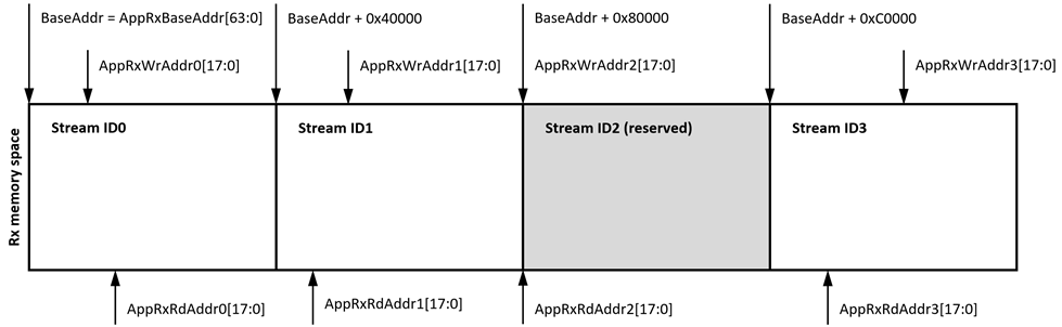
Figure 16: Receive memory structure
The circular buffer concept is also applied to the User Rx interface. In this direction, however, the IP will write data to the receive buffer, and according to the protocol, it is possible that the data might not be in order. As depicted in Figure 17a, 5 bytes are available and confirmed by WrPtr and RdPtr from address 1 – 5. Other spaces in the memory can be filled with valid data but cannot yet be confirmed by WrPtr because it is not continuous. This case can also be seen in our QUIC10GC-IP environment and therefore, the users should threat the receive buffer as a read-only buffer.
As soon as the missing data is retransmitted to the IP, the new position of WrPtr will be recalculated and presented to the users. In Figure 17b, for example, if data at address 6, 7, and 10 are received, the IP will fill the data and then update WrPtr to the point where it is highest and continuous, which is address 11.
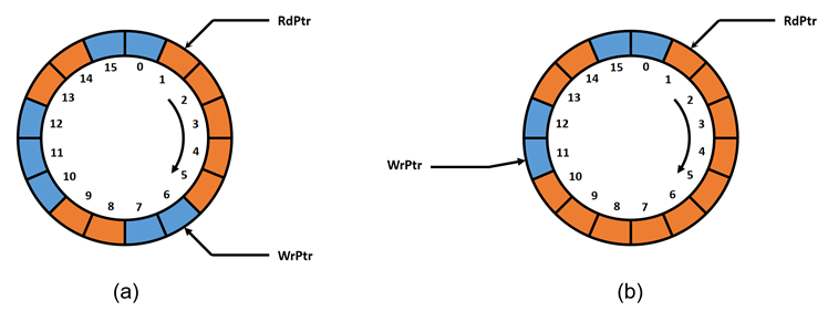
Figure 17: Example of the circular buffer concept in the receive buffer
The receive buffer uses AppRxWrAddrX[17:0] as the write pointer (WrPtr) and AppRxRdAddrX[17:0] as the read pointer (RdPtr), where 'X' represents the streamID. When a new connection is opened, AppRxWrAddrX[17:0] will be moved to the location of AppRxRdAddrX[17:0], ensuring that the receive buffer is initially empty. During data transfer, the QUIC10GC-IP uses the AXI4 protocol to write incoming data of the Stream ‘X’ into the receive buffer, only after which it will update AppRxWrAddrX[17:0] to point to the next valid and continuous data position. After processing the data in the receive buffer of the Stream ‘X’, the user updates AppRxRdAddrX[17:0] to the next read position, allowing the IP to reuse the buffer up to that section.
If the other endpoint requests to close the stream ‘X’, the QUIC10GC-IP will set AppRxWrFinX to ‘1’ along with the last valid address of AppRxWrAddrX[17:0]. After this, there will be no data received in Stream ‘X’.
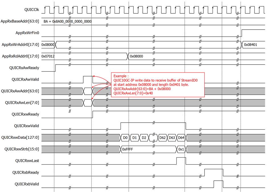
Figure 18: Example of QUIC10GC-IP write data to receive memory
To transfer data to memory, similar to the User Tx data interface, an AXI4 write controller is included in the User Rx data interface. The following constraints are applied:
· The burst attribute is set to INCR (AWBURST=0b00), indicating that the address for each transfer is incremented.
· Transfers can be unaligned, utilizing an unaligned start address and byte lane strobes.
· Single AXI4 transactions are applied.
· AWSIZE is set to 0b100, indicating 16 bytes per transfer.
· AWLEN is not fixed to 2, 4, 8, or 16.
· Maximum transaction bytes are capped at 4096 bytes per transaction.
· The address for each transfer is guaranteed to always be within a memory boundary.
· BRESP is not presented and assumed to be 0b000 (OKAY), and BCOMP is not presented.
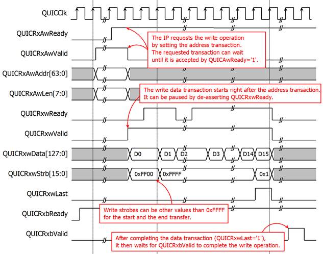
Figure 19 AXI4 write operation for the User Rx data interface
The above illustration shows the AXI4 write operation used by the IP to write data to the memory. Only a single access of the write operation is performed at a time. It starts by sending the address transaction, asserting QUICRxAwValid to ‘1’ along with two associated values, QUICRxAwAddr and QUICRxAwLen. The first value is the start address of the write position in the memory, and the other is the transfer length. This timing diagram, for example, presents the transfer of D0 – D15, where QUICRxAwLen must be 0xF.
The completion of the address transaction is indicated by the assertion of both QUICRxAwReady and QUICRxAwValid. After one clock cycle, the data transaction begins by asserting QUICRxwValid to ‘1’ with the valid values of QUICRxwData, QUICRxwStrb and QUICRxwLast. When QUICRxwLast is valid and asserted to ‘1’, the data transaction is completed. At the end, the IP waits for the write response from QUICRxbValid.
Discontinuous transfers of the address and data transaction are supported. QUICRxAwReady can be ‘0’, and the address transaction holds valid values, while the data transaction is paused when QUICRxwReady is set to ‘0’. Furthermore, QUICRxbReady is always asserted to ‘1’ to receive the write response.
For unaligned data transfer, QUICRxAwAddr[3:0] can be set to any value other than 0x0, and the first and the last write strobes (QUICRxwStrb) can be set to other values than 0xFFFF for writing the data into a particular byte address. In this example, QUICRxAwAddr[3:0] must be set to 0x8 so that the first QUICRxwStrb is 0xFF00.
Table 4: User Rx information
|
Name |
Type[7:0] |
ID[7:0] |
D0[63:0] |
D1[63:0] |
|
RESET_STREAM |
0x04 |
StreamID |
Application Protocol Error Code |
Final Size |
|
STOP_SENDING |
0x05 |
StreamID |
Application Protocol Error Code |
- |
|
DATA_BLOCKED |
0x14 |
- |
Maximum Data |
- |
|
STREAM_DATA_BLOCKED |
0x15 |
StreamID |
Maximum Stream Data |
- |
|
STREAMS_BLOCKED |
0x16 - 0x17 |
- |
Maximum Streams |
- |
While the QUIC connection is established and enters the data transfer phase, specific QUIC frame types can be passed to the user for system monitoring purposes. These frame types are detailed in Table 4 and are communicated to the user through the User Rx Information interface.
For example, if a DATA_BLOCKED (0x14) frame is encountered, it will be sent to the user via the QUICRxInfoType signal, with the associated parameter Maximum Data presented through the QUICRxInfoD0 signal. This information indicates that the remote QUIC endpoint is attempting to send data but is being blocked by flow control constraints.
Receiving such frames allows users to identify issues in detail and subsequently manage their system more effectively. In the given scenario, users could release the used Rx buffer space back to the IP, enabling the remote QUIC endpoint to continue sending data. This monitoring and management can help maintain optimal data flow and system performance during QUIC data transfers.
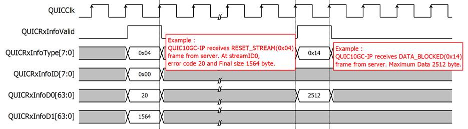
Figure 20: Example of User Rx information
· Alert handling
In the QUIC protocol, a sender can send alert messages to indicate closure information and errors to the receiver. The QUIC10GC-IP is designed to support such alert messages, as shown in Table 5. It uses the QUICAlertCode[15] to represent the direction of the error code, asserting to ‘1’ when an error is received from the server and asserting to ‘0’ when an error arises from the QUIC10GC-IP. The QUICAlertCode[14:0], represents the specific error code.
Table 5: Alert code description
|
Alert Code |
Alert Message |
Description |
|
QUIC error codes |
||
|
0x0000 |
NO_ERROR |
Closed connection without error. |
|
0x0001 |
INTERNAL_ERROR |
Encountered unsupported features or resource exhausted. |
|
0x0003 |
FLOW_CONTROL_ERROR |
Received data that exceeds limit. |
|
0x0004 |
STREAM_LIMIT_ERROR |
Opened streamID that exceeds limit. |
|
0x0005 |
STREAM_STATE_ERROR |
Violated protocol in the stream level. |
|
0x0006 |
FINAL_SIZE_ERROR |
Received a frame that violates the final size agreement. |
|
0x0007 |
FRAME_ENCODING_ERROR |
Received data that does not follow the QUIC encoding format. |
|
0x0008 |
TRANSPORT_PARAMETER_ERROR |
Received a handshake message with invalid QUIC transport parameters. |
|
0x000A |
PROTOCOL_VIOLATION |
Received a frame in an incorrect packet type. |
|
0x000D |
CRYPTO_BUFFER_EXCEEDED |
Received a crypto frame that exceeds the size of the crypto buffer. |
|
TLS alert code |
||
|
0x010A |
TLS_UNEXPECTED_MESSAGE |
Received an out-of-sequence message: the packet type of received handshake packet is not matched to the expected packet type. |
|
0x0128 |
TLS_HANDSHAKE_FAILURE |
Indicated that the sender was unable to negotiate an acceptable set of security parameters given the options available. For example, when the QUIC10GC-IP validates a ServerHello in handshake step 2, the option TLS_AES_128_GCM_SHA256 is not available in the server’s cipher suite. |
|
0x012B |
TLS_UNSUPPORTED_CERTIFICATE |
Received an unsupported certificate type. |
|
0x012F |
TLS_ILLEGAL_PARAMETER |
Received the extensions with an invalid value. |
|
0x0132 |
TLS_DECODE_ERROR |
Received a message that cannot be decoded because some fields are out of the specified ranges, or the length of the message is incorrect. |
|
0x0133 |
TLS_DECRYPT_ERROR |
Failed during handshake cryptographic operation: unable to correctly verify a signature or validate a finished message. |
|
0x0146 |
TLS_PROTOCOL_VERSION |
Failed to handshake with the server due to the fact that the TLS version is not 1.3. |
|
0x0150 |
TLS_INTERNAL_ERROR |
Indicated that the server does not response within a specific timeout period, while the IP is waiting for the handshake packet returned from the target device. |
|
User error code |
||
|
0x1000 |
TARGET_TIMEOUT_ERROR |
Indicated that the server does not response within a specific Idle timeout. |
|
0x1001 |
ABNORMAL_CLOSE_ERROR |
Indicated that the user de-asserts “ConnOn” signal to ‘0’ when QUICHandshakeBusy, QUICTxTrnsBusy, and QUICRxTrnsBusy are still busy, any of which is asserted to ‘1’. |
|
0x1002 |
OPEN_CONNECTION_TIMEOUT |
Indicated that the IP cannot connect to a network system. |
|
0x1003 |
ALPN_SIZE_ERROR |
Indicated that user inputs an unsupported value of QUICALPNLen, which is when QUICALPNLen is greater than 16 bytes. |
* QUIC10GC-IP can present an alert code from a server only in format of 15-bit value.
· MAC Interface
The MAC interface of the QUIC10GC-IP uses simple streaming data interface similar to the AXI4-Stream interface. It is used to transmit and receive packets, which are reduced Ethernet frames. According to IEEE 802.3, this reduced frame includes only the destination address, source address, length and data.
When the QUIC10GC-IP requests to send a packet, it sets MacTxValid to ‘1’ along with the valid values of MacTxData, MacTxSOP, MacTxEOP and MacTxByteEn. The transmission can be paused if MacTxReady is de-asserted to '0' at any clock cycle and resumed afterward. MacTxByteEn[3:0] indicates which bytes within MacTxData[31:0] are valid. For example, MacTxByteEn[0] indicates the validity of MacTxData[7:0], and MacTxByteEn[1] for the validity of MacTxData[15:8]. MacTxSOP is set to indicate the start of a packet, while MacTxEOP is asserted to indicate the end of a packet. Figure 21 depicts an example of sending a packet.
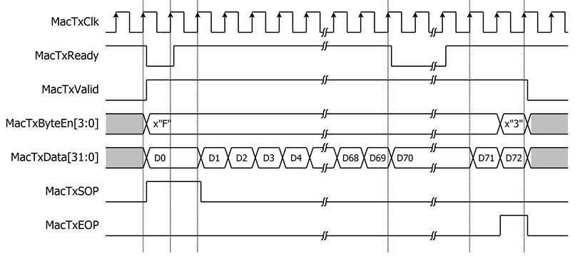
Figure 21: Transmit MAC Interface timing diagram
On the other hand, Figure 22 shows an example of receiving a packet. To start receiving a packet, MacRxValid is asserted to indicate valid data on MacRxData[31:0]. MacRxByteEn[3:0] is used to indicate which bytes within MacRxData[31:0] are valid, and MacRxEOP is asserted to indicate the end of a packet. If an error occurs during reception, MacRxError will be asserted to ‘1’ at the end of the packet, and the receiving packet will be discarded. In this example, the reception of data (D0 to D72) happens when MacRxValid is asserted.
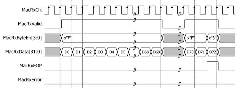
Figure 22: Receive MAC Interface timing diagram
Verification Methods
The QUIC10GC-IP Core functionality was verified by simulation and also proved on real board design by using ZCU106 Evaluation Board.
Recommended Design Experience
The user must be familiar with HDL design methodology to integrate this IP into a system.
Ordering Information
This product is available directly from Design Gateway Co., Ltd. Please contact Design Gateway Co., Ltd. For pricing and additional information about this product, use the contact information on the front page of this datasheet.
Revision History
|
Revision |
Date |
Description |
|
1.00 |
2-Jul-24 |
Initial release |