2.3 Network properties settings
4 FPGA development board setup
7 Test setup when using 2 FPGA boards
7.1 Environment setup when using 2 FPGA boards
7.2.1 Set parameters and start a server
7.2.2 Client download data test
7.2.4 Client download/upload data test (Full duplex)
This document provides detailed instructions to demonstrate the use of the QUIC Server 10Gbps IP core (QUIC10GS-IP) on our reference design, referred to as the “QUIC10GS-IP Reference Design”, using the KCU116 development board. The QUIC10GS-IP is used as a medium to transfer data within a secure connection following the QUIC transport protocol version 1 standard (RFC9000). This process involves handling the TLS 1.3 handshake and dealing with data encryption and decryption.
The reference design uses the QUIC10GS-IP and manages the application layer of the IP. It is tailored to test the IP functionality, to help users understand how to use the IP, and to offer flexibility for users in case they need to modify the design. The main application demonstrated in this reference design is a unique application protocol designed by an organization to use with their application.
This instruction will explain step-by-step how users can utilize the QUIC10GS-IP through our reference design for uploading and downloading data. MsQuic is employed as a client to show the transfer performance using the unique application protocol.
Following our document guidelines, this document will describe how to set up the environment for the test, provide more details about the reference example (MsQuic), and instruct and show the results of the test, respectively.
1 Environment Setup
To run the QUIC10GS-IP demo, please prepare following test environment.
1) FPGA development boards (KCU116 development board).
2) Test PC with 10 Gigabit Ethernet or connecting with 10 Gigabit Ethernet card.
3) 10 Gb Ethernet cable:
a) 10 Gb SFP+ Passive Direct Attach Cable (DAC) which has 1-m or less length
b) 10 Gb SFP+ Active Optical Cable (AOC)
c) 2x10 Gb SFP+ transceiver (10G BASE-R) with optical cable (LC to LC, Multimode)
4) Micro USB cable for JTAG connection connecting between FPGA board and Test PC.
5) Micro USB cable for UART connection connecting between FPGA board and Test PC.
6) Vivado tool for programming FPGA installed on Test PC.
7) Serial console software such as TeraTerm installed on PC. The setting on the console is Baudrate=115200, Data=8-bit, Non-parity and Stop=1.
8) Demo configuration file (To download this file, please visit our web site at www.design-gateway.com).
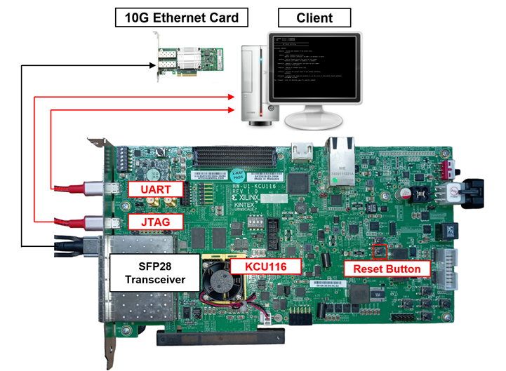
Figure 1 QUIC10GSIP demo environment on KCU116 board
2 PC Setup
Before running demo, please check the network setting on PC. The example of setting 10 Gb Ethernet card is described as follows.
2.1 IP setting
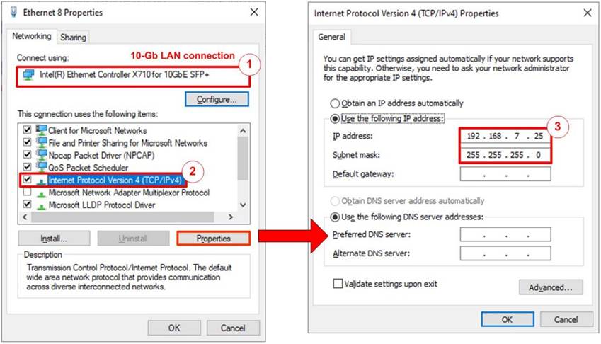
Figure 2 Setting IP address for PC
1) Open Local Area Connection Properties of 10 Gb connection, as shown in the left window of Figure 2.
2) Select “TCP/IPv4” and then click Properties.
3) Set IP address = 192.168.7.25 and Subnet mask = 255.255.255.0, as shown in the right window of Figure 2.
2.2 Speed and duplex settings
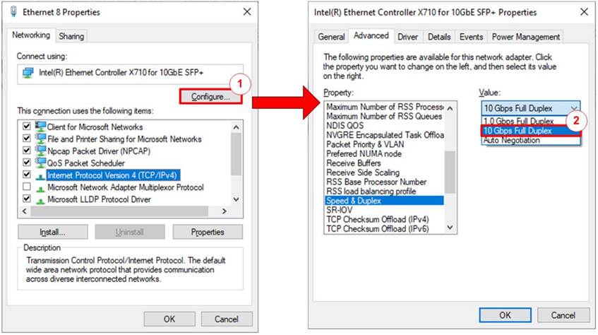
Figure 3 Set Link Speed = 10 Gbps
1) On Local Area Connection Properties window, click “Configure”, as shown in Figure 3.
2) On Advanced Tab, select “Speed and Duplex”. Set the value to “10 Gbps Full Duplex” for running 10 Gigabit transfer test, as shown in Figure 3.
2.3 Network properties settings
Some of network parameter settings may affect network performance. The example of network properties setting is as follows.
1) On “Interrupt Moderation” window, select “Disabled” to disable interrupt moderation which would minimize the latency during transferring data, as shown in Figure 4.
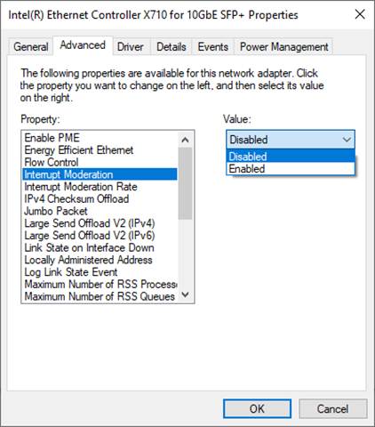
Figure 4 Interrupt Moderation
2) On “Interrupt Moderation Rate” window, set the value to “OFF”, as shown in Figure 5.
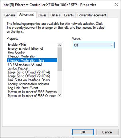
Figure 5 Interrupt Moderation Rate
3) On “Jumbo packet” window, set the value to “9014 Bytes”, as shown in Figure 6.
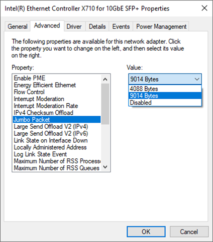
Figure 6 Jumbo packet
4) On “Receive Buffers” window, set the value to the maximum value, as shown in Figure 7.
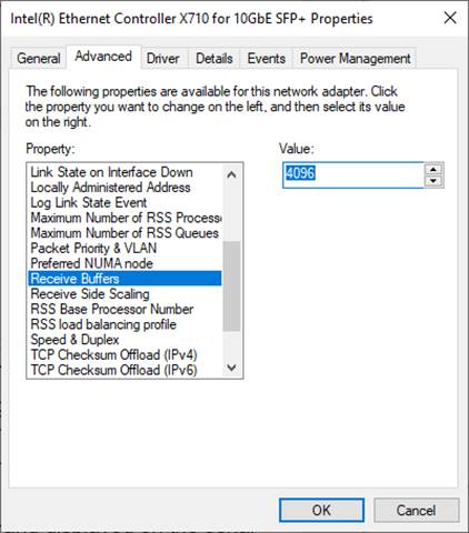
Figure 7 Receive Buffers
5) On “Transmit Buffers” window, set the value to the maximum value, as shown in Figure 8.
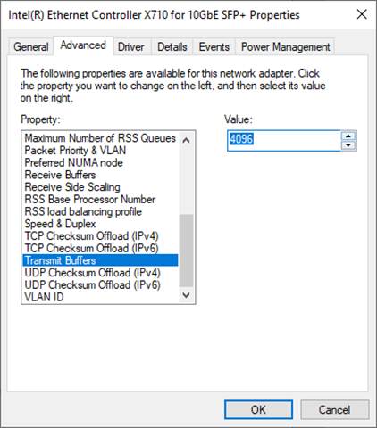
Figure 8 Transmit buffers
3 MsQuic server
QUIC software implementation used in our reference is MsQuic, developed by Microsoft. Their work is an open-source software project, written in C and published in the following website: github.com/microsoft/msquic. We use MsQuic version 2.3.5 and would like to thank Microsoft and the MsQuic team for the development of MsQuic. There is no modification of MsQuic required to run with our demonstration, but we included a folk of MsQuic as a reference branch that we use in this repository: github.com/design-gateway/msquic. If you have any questions regarding their core, please kindly direct them to the MsQuic development team.
There are several application examples offered by MsQuic, but for our reference, an application called ‘secnetperf’ is applied to run with our demo due to the fact that it is optimized for the high-performance data transfer. For this reason, it uses its own application protocol rather than using the HTTP/3 protocol. Please follow MsQuic’s guidelines to set up the application.
To run an MsQuic server using the secnetperf application, secnetperf.exe is called with two options – one is the IP address to bind the server to, and the other is the profile setting of this application, configured for maximum performance in this example. After running the binary file, the message displaying “Started!” is shown as a result, and there will be no other messages thereafter. The example of running the MsQuic is illustrated in Figure 9.

Figure 9 MsQuic server application console
At this point, a client running the secnetperf application can be connected to the server. To run the client, four options are used in this example: “target” being the IP address of the server to be connected to, “exec” being the same setting as of the server, “up/down” being the length of the upload or download, and “ptput” being the setting to print throughput information. The example of the client console uploading data from the server is shown in Figure 10, while the example of downloading data to the server is shown in Figure 11.
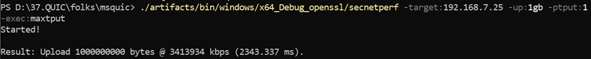
Figure 10 MsQuic client application console uploading data
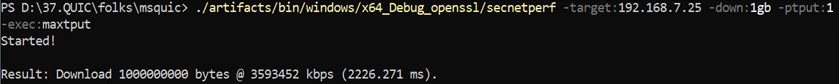
Figure 11 MsQuic client application console downloading data
4 FPGA development board setup
1) Make sure the power switch is off and connect the power supply to KCU116 development board.
2) Connect USB cable between PC to JTAG micro-USB port.
3) Power on the system.
4) Open Vivado Hardware Manager to program FPGA by following steps.
a) Click open Hardware Manager.
b) Open target -> Auto Connect.
c) Select FPGA device to program bit file.
d) Click Program device.
e) Click “…” to select program bit file.
f) Click Program button to start FPGA Programming.
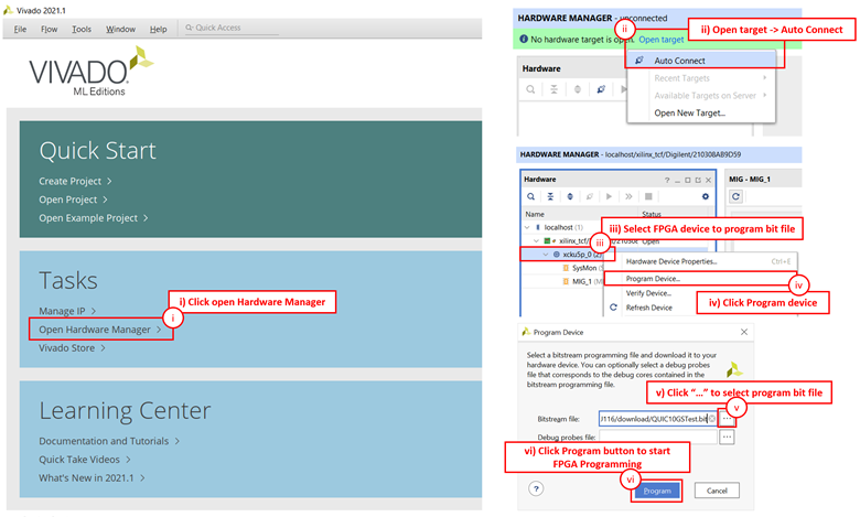
Figure 12 Program Device
5 Serial Console
Users can set the parameters or run the Listen application by using the following commands. The QUIC10GSdemo commands and their usages will be displayed, as shown in Figure 13. Detailed information about each command is described in topic 6.
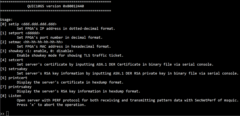
Figure 13 Serial console
6 Command detail
6.1 Set FPGA’s IP Address
command> setip ddd.ddd.ddd.ddd
This command is used to set the FPGA’s IP address in dotted-decimal format. The default FPGA’s IP address is 192.168.7.42. Users can input the setip command followed by a valid IP address, as shown in Figure 14.
6.2 Set FPGA’s Port Number
command> setport ddddd
This command is used to set the static port number of FPGA in decimal format. The default FPGA’s Port number is 4433. Users can input the setport command followed by a valid Port number, as shown in Figure 14.
6.3 Set FPGA’s MAC address
command> setmac hh-hh-hh-hh-hh-hh
This command is used to set the FPGA’s MAC address in hexadecimal format. The default FPGA’s MAC address is 80-11-22-33-44-55, which is a unicast MAC address. Users can input the setmac command followed by a valid MAC address, as show in Figure 14.
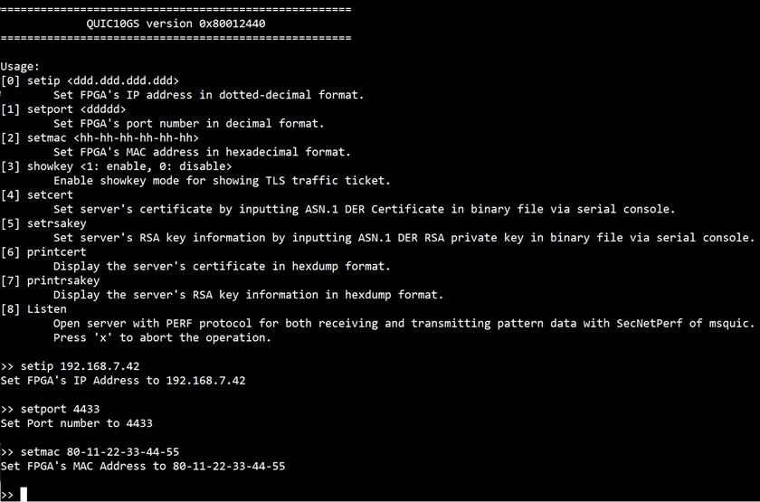
Figure 14 Serial console when set network parameter
6.4 Enable showkey mode
command> showkey <1: enable, 0: disable>
This command is used to enable the showkey mode. When the showkey mode is enabled, the TLS traffic ticket for encryption/decryption is displayed on the serial console, as shown in Figure 15. Users can utilize the TLS traffic ticket in the (Pre)-Master-Secret log file for Wireshark*, enabling them to decrypt transferred data between the client and server.
*Wireshark, a network packet analyzer tool used for network troubleshooting, analysis, and security purposes.
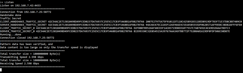
Figure 15 Serial console when the showkey mode is enabled
6.5 Set certificate
command> setcert
This command is used to set the server’s certificate, which must be valid before starting a server. The supported certificate format is ASN.1 DER as a binary file. If the certificate is in PEM format, it must be converted to ASN.1 DER using the following OpenSSL command:
openssl x509 -in <input_file>.pem -out <output_file>.der -outform der
As shown in Figure 16, the output certificate will be in binary format. Users can send the binary certificate file (cert.der) via the serial console as Figure 17. In this demonstration, the maximum supported certificate file size is 8 KB.
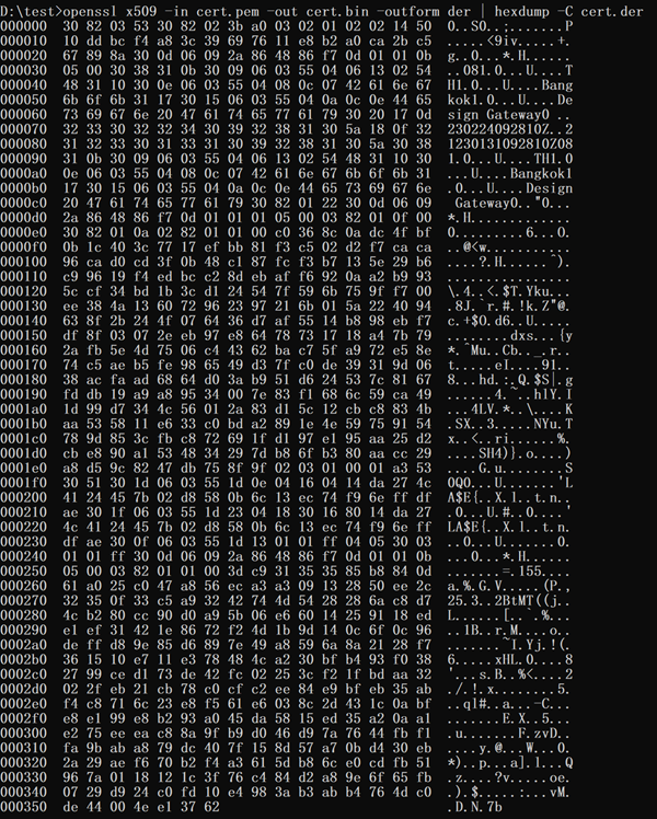
Figure 16 Certificate information from openssl command
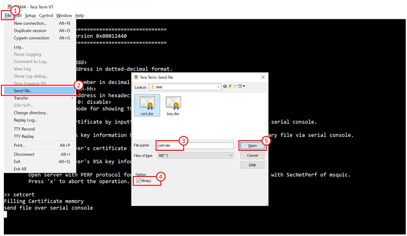
Figure 17 Example binary file transfer
6.6 Set RSA key information
command> setrsakey
This command is used to set RSA key information, which must be valid before starting the server. The supported RSA key format is ASN.1 DER as a binary file. If the RSA key is in PEM format, it must be converted to ASN.1 DER using the following OpenSSL command:
openssl rsa -in <input_file>.pem -out <output_file>.der -outform der
As shown in Figure 18, the output RSA key will be in binary format. Users can send the binary RSA key file (key.der) via the serial console. In this demonstration, the maximum supported RSA key size is 2 KB.
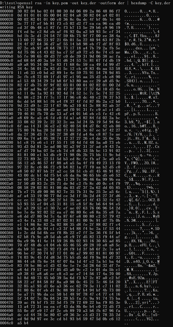
Figure 18 RSA key information from openssl command
6.7 Print certificate
command> printcert
This command is used to display the server’s certificate. The output is in ASN.1 DER format and shown in a structured hexadecimal representation. This helps to ensure that the certificate is correctly set and valid before the server starts.
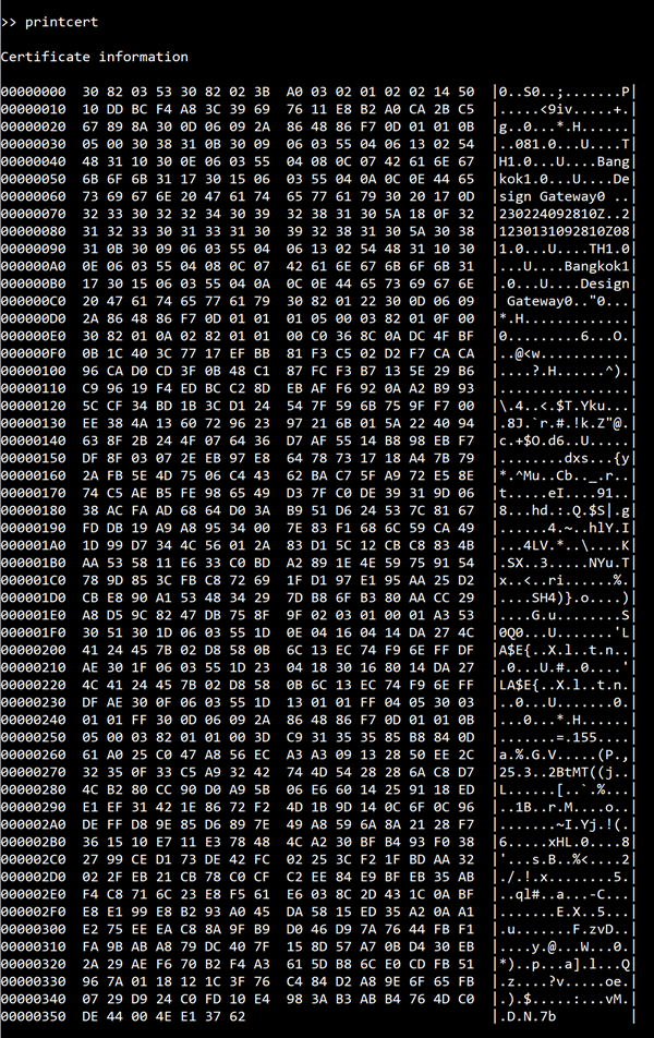
Figure 19 Serial console when print certificate
6.8 Print RSA key information
command> printrsakey
This command is used to show the server’s rsa key. The output is in ASN.1 DER format and shown in a structured hexadecimal representation. This helps to ensure that the rsa key is correctly set and valid before the server starts.
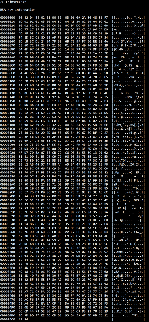
Figure 20 Serial console when print rsa key
6.9 Start a server
Command> listen
The listen command is used to run the ‘secnetperf’ example of an MsQuic client. The server listens for incoming connections on the FPGA IP address and port number. When a connection is established by the client, the server responds to incoming data based on supported requests from the client.
The verification feature is enabled to monitor the received data. The results, including download content, transfer length, and transfer speed, are presented (see Figure 21). It’s important to note that the performance of this operation depends on the network system and available resources on the test machine.
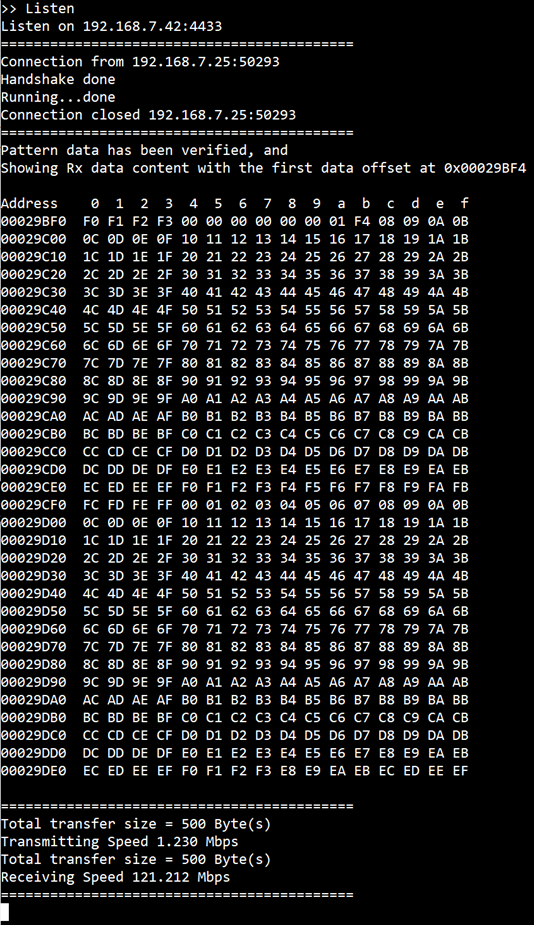
Figure 21 Serial console when downloading small data
However, Figure 21 may not be ideal for representing transfer performance because the operation time is too short for accurate calculations. Figure 22 shows transfer speed for server receiving, while Figure 23 presents speed for server transmitting. Figure 24 provides transfer speed for both transmitting and receiving, as the transfer size settings are large enough for meaningful results.
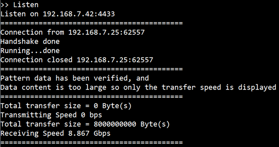
Figure 22 Serial console display during server receiving large data
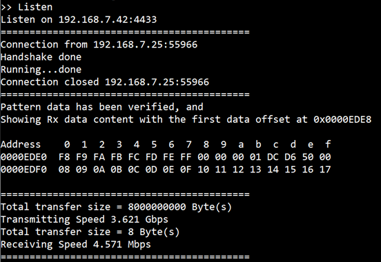
Figure 23 Serial console display during server transmitting large data
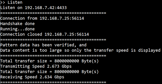
Figure 24 Serial console display during server transmitting and receiving large data
7 Test setup when using 2 FPGA boards
This test setup evaluates performance between two FPGA boards using the QUIC10GC-IP as the client and the QUIC10GS-IP as the server, ensuring no bottleneck from CPU software. The test utilizes a secure connection over the QUIC transport protocol, enabling high-speed data transfer with hardware acceleration. At the application layer, a dedicated protocol—similar to MsQuic’s ‘secnetperf’ example—is implemented to measure performance. This setup enables a fully hardware-driven QUIC communication, independent of software processing constraints.
7.1 Environment setup when using 2 FPGA boards
To operate QUIC10GS-IP demo with QUIC10GC-IP demo, please prepare following test environment.
1) FPGA development boards (KCU116 as a server and ZCU106 as a client).
2) 10 Gb Ethernet cable:
a) 10 Gb SFP+ Passive Direct Attach Cable (DAC) which has 1-m or less length
b) 10 Gb SFP+ Active Optical Cable (AOC)
c) 2x10 Gb SFP+ transceiver (10G BASE-R) with optical cable (LC to LC, Multimode)
3) Micro USB cable for JTAG connection connecting between FPGA board and Test PC.
4) 2 Micro USB cable for UART connection connecting between KCU116 board and Test PC and between ZCU106 board and Test PC.
5) Vivado tool for programming FPGA installed on Test PC.
6) Serial console software such as TeraTerm installed on PC. The setting on the console is Baudrate=115200, Data=8-bit, Non-parity and Stop=1.
7) Batch file named “QUIC10GSIPTest.bit” and “QUIC10GCIPTest.bat” (To download these files, please visit our website at www.design-gateway.com)
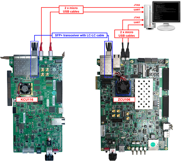
Figure 25 QUIC10GS-IP demo environment when using 2 FPGA boards
Follow step 1)-4) of Topic 4 Board setup to prepare FPGA boards for running the demo. Run “QUIC10GSTest.bit” to download configuration file and firmware to KCU116 board as a server and run “QUIC10GCTest.bat” to download configuration file and firmware to ZCU106 board as a client. The details of supported commands and their usage for QUIC10GC-IP demo is described in the following link.
https://dgway.com/products/IP/QUIC-IP/QUIC10GCIP-instruction-xilinx-en/
7.2 Test sequence
7.2.1 Set parameters and start a server
1) Set network parameters of each FPGA board: IP address, port number, and Mac address.
2) Set server’s certificate and RSA key information via serial console of server.
3) Start the server, allowing it to listen for incoming connections.
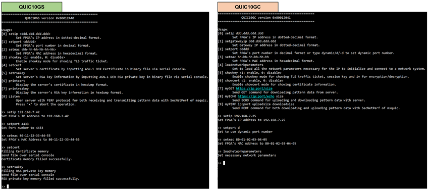
Figure 26 Server and client console display with configured parameters
7.2.2 Client download data test
command> myPERF <serverIP>:<serverPort> 0 <downloadSize>
Enter the command through the client’s console, the client sends a request to download data from the server. The server responds by transmitting a data pattern of the specified size. Once the transfer is complete, both the client and server consoles display the transfer results and speed, as shown in Figure 27.
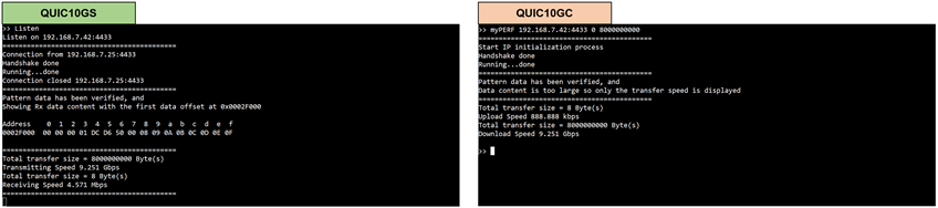
Figure 27 Server and client console display during data transfer from server to client
7.2.3 Client upload data test
command> myPERF <serverIP>:<serverPort> <uploadSize> 0
Enter the command through the client’s console, the client generates and transmits a data pattern to the server. The server receives and processes the incoming data. Once the transfer is complete, both the client and server consoles display the transfer results and speed, as shown in Figure 28.
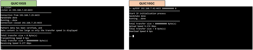
Figure 28 Server and client console display during data transfer from client to server
7.2.4 Client download/upload data test (Full duplex)
command> myPERF <serverIP:<serverPort> <uploadSize> <downloadSize>
Enter the command through the client’s console, the client simultaneously sends an upload data pattern and requests a download data pattern from the server. The server responds by transmitting the requested data while receiving the client’s data. Once the transfer is complete, both consoles display the transfer results and speed, as shown in Figure 29.
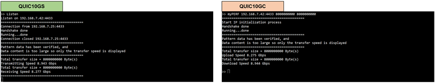
Figure 29 Server and client console display during Full-Duplex data transfer
8 Test Result
The performance test for QUIC10GS-IP on an FPGA board was conducted using QUIC10GS-IP as the QUIC server. At the application layer, a dedicated protocol—similar to MsQuic’s ‘secnetperf’ example—was implemented to measure performance. The results compare the performance of QUIC10GS-IP with MsQuic’s software as a client on a PC and QUIC10GS-IP with QUIC10GC-IP as a client on an FPGA.
When MsQuic, a software-based QUIC client running on a PC, downloads data from QUIC10GS-IP, the throughput is approximately 3.5 Gbps, while the upload speed reaches 8.7 Gbps. In the case of simultaneous upload and download, the throughput is around 2.5 Gbps. The utilization of the Intel i7 CPU is approximately 100%, as monitored by the PC’s task manager. This indicates that the CPU is fully utilized when handling QUIC data transfer over the network.
On the other hand, when using QUIC10GC-IP as a client, the download speed from QUIC10GS-IP is approximately 9.2 Gbps, the upload speed is also 9.2 Gbps, and in the case of simultaneous upload and download, the throughput reaches 8.3 Gbps, as shown in Table 1.
Table 1 QUIC10GS-IP Performance test result
|
Client |
Download (Gbps) |
Upload (Gbps) |
Full Duplex (Gbps) |
CPU Utilization |
|
MsQuic (Software on PC) |
3.5 |
8.7 |
2.5 |
~100% |
|
QUIC10GC-IP (on FPGA) |
9.2 |
9.2 |
8.3 |
- |
9 Revision History
|
Revision |
Date (D-M-Y) |
Description |
|
1.00 |
12-Mar-25 |
Initial version release |