exFAT IP Core for SATA Data Sheet
DG SATA HCTL IP and DG SATA IP

Core Facts |
|
|
Provided with Core |
|
|
Documentation |
User Guide, Design Guide |
|
Design File Formats |
Encrypted HDL |
|
Instantiation Templates |
VHDL |
|
Reference Designs & Application Notes |
QuartusII Project, See Reference Design Manual |
|
Additional Items |
Demo on Arria10 SoC/Cyclone10 GX Development Kit |
|
Support |
|
|
Support Provided by Design Gateway Co., Ltd. |
|
Design Gateway Co.,Ltd
54 BB Building 14th Fl., Room No.1402 Sukhumvit 21 Rd. (Asoke), Klongtoey-Nua, Wattana, Bangkok 10110
Phone: 66(0)2-261-2277
Fax: 66(0)2-261-2290
E-mail: ip-sales@design-gateway.com
URL: www.design-gateway.com
Features
· Access SATA device as exFAT system without using CPU and external memory
· Simple user interface and operating with DG SATA HCTL IP suite
· Achieve the best write/read speed (up to 533 MB/s for write and up to 560 MB/s for read)
· Support device capacity: 8 Gigabyte* – 64 Petabyte*
*Gigabyte means 1024x1024x1024 byte while Petabyte means 1024x1024x1024x1024x1024 byte
· Three user commands, i.e. Format, Write file, and Read file
· Support eight file sizes, i.e. 32MB, 128MB, 512MB, 2GB, 8GB, 32GB, 128GB, and 512GB (some file sizes are not available for some device capacities)
· Reference design available on Arria10 SoC/Cyclone10 GX development board with AB09-FMCRAID
Table 1: Example Implementation Statistics
|
Family |
Example Device |
Fmax (MHz) |
Logic utilization (ALMs) |
Registers1 |
Pin |
Block Memory bit |
Design Tools |
|
Arria10 SX |
10AS066N3F40E2SG |
384 |
1,424 |
2,094 |
- |
98,304 |
QuartusII 18.0 |
|
Cyclone10 GX |
10CX220YF780E5G |
370 |
1,423 |
2,094 |
- |
98,304 |
QuartusII 18.0 |
Notes:
1) Actual logic resource dependent on percentage of unrelated logic
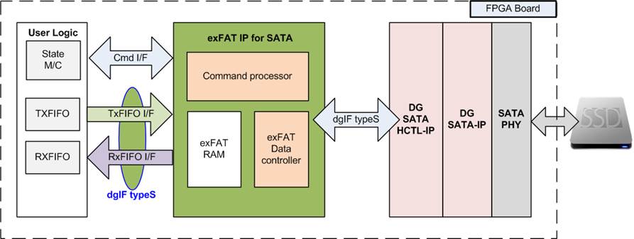
Figure 1: exFAT IP for SATA Block Diagram
Applications
exFAT IP for SATA must operate with SATA HCTL IP suite (DG SATA HCTL IP and DG SATA IP) and SATA PHY. The IP Core is an ideal to access SATA device as exFAT file system with high speed performance, like raw data access. This solution fits the application which needs to record data to SATA device by FPGA, but the data file is read by other hosts such as PC through file system format.
General Description
In general system, CPU and firmware are applied to write or read data with the device as file system. So, the system must include CPU and memory to store CPU firmware. Write performance and Read performance when access the device as file system by using CPU firmware are not good. There is much overhead time for CPU managing file system which is effect to reduce the performance. Finally, most users decide to make their own file system to achieve the good performance without using standard file system.
To solve above problem, exFAT IP for SATA is designed to meet two requirements, i.e. using less FPGA resource (no CPU and no external memory) and writing/reading data at the highest speed like raw data access. exFAT IP for SATA is top-up module of SATA HCTL IP to allow user write/read data with SATA device as exFAT file system instead of raw data (raw data system could be designed by using only SATA HCTL IP). The interface of exFAT IP for SATA is simple and almost similar to SATA HCTL IP. User interface of exFAT IP could be split to two groups, i.e. control interface and data interface.
Control interface is almost similar to SATA HCTL IP, but file parameters are used instead of physical parameters. File name is used to specify starting point to access data, instead of physical address. The number of written/read files is used to specify transfer size, instead of physical length. Three commands are designed in exFAT IP to access SATA device, i.e. Format, Write file, and Read file.
Data interface of exFAT IP is designed by using general FIFO interface, same as SATA HCTL IP. Clock domain of exFAT IP must be same as user clock of SATA HCTL IP because there is no asynchronous circuit included to interface between exFAT IP and SATA HCTL IP.
Otherwise, user needs to input file parameters to exFAT IP such as created date and created time. Created date and created time must be valid during sending command request to exFAT IP. File size must be set during running Format operation. Eight file size could be selected, i.e. 32 MB, 128 MB, 512 MB, 2 GB, 8 GB, 32 GB, 128 GB, and 512 GB. More details of supported file size are shown in Table 2.
Table 2: Supported file size following device capacity
|
Device capacity |
32MB(2) |
128MB(2) |
512MB(2) |
2GB(2) |
8GB(2) |
32GB(2) |
128GB(2) |
512GB(2) |
|
8 GB - 16 GB(1) |
Yes |
Yes |
Yes |
Yes |
No |
No |
No |
No |
|
16 GB – 64 GB(1) |
Yes |
Yes |
Yes |
Yes |
Yes |
No |
No |
No |
|
64 GB – 256 GB(1) |
Yes |
Yes |
Yes |
Yes |
Yes |
Yes |
No |
No |
|
256 GB – 1 TB(1) |
Yes |
Yes |
Yes |
Yes |
Yes |
Yes |
Yes |
No |
|
1 TB – 512 TB(1) |
Yes |
Yes |
Yes |
Yes |
Yes |
Yes |
Yes |
Yes |
|
512 TB – 8 PB(1) |
No |
Yes |
Yes |
Yes |
Yes |
Yes |
Yes |
Yes |
|
8 PB – 64 PB(1) |
No |
No |
Yes |
Yes |
Yes |
Yes |
Yes |
Yes |
Note
(1) The upper limit of device capacity must be less than this value. For example, when device capacity is 512 TB, row 512 TB – 8 PB must be used instead of 1TB – 512 TB.
(2) In the table, MB means 1024x1024 byte. GB means 1024x1024x1024 byte.
TB means 1024x1024x1024x1024 byte. PB means 1024x1024x1024x1024x1024 byte.
When running Format command, file size input to exFAT IP must be fixed. File size input is not used when running other commands. After finishing Format command, 512 empty directories are created in the device, i.e. DIR000, DIR001, …, DIR0FF, DIR100, … , DIR1FE, and DIR1FF. Three hexadecimal digits are used to refer directory number.
When running Write file command operation, the new file is created to the device. Filename is fixed to seven hexadecimal digits. The 1st file name is 0000000.BIN and stored to DIR000. The next files (0000001.BIN, 0000002.BIN, … ) are also stored to DIR000. When total file in DIR000 is equal to maximum file per directory (DirCap signal), the next file is stored to the next directory (DIR001). Maximum file per directory depends on device capacity, as shown in Table 3.
Table 3: Maximum file per directory
|
Device capacity |
DirCap[19:0] |
Used directory |
|
8 GB - 32 GB(1) |
0x00100 (256) |
DIR000 - DID003 |
|
32 GB – 128 GB(1) |
0x00200 (512) |
DIR000 - DIR007 |
|
128 GB – 512 GB(1) |
0x00400 (1024) |
DIR000 – DIR00F |
|
512 GB – 2 TB(1) |
0x00800 (2048) |
DIR000 – DIR01F |
|
2 TB – 8 TB(1) |
0x01000 (4096) |
DIR000 – DIR03F |
|
8 TB – 32 TB(1) |
0x02000 (8192) |
DIR000 – DIR07F |
|
32 TB – 128 TB(1) |
0x04000 (16384) |
DIR000 – DIR0FF |
|
128 TB – 512 TB(1) |
0x08000 (32768) |
DIR000 – DIR1FF |
|
512 TB – 2 PB(1) |
0x10000 (65536) |
DIR000 – DIR0FF |
|
2 PB – 8 PB(1) |
0x20000 (131072) |
DIR000 – DIR1FF |
|
8 PB – 32 PB(1) |
0x40000 (262144) |
DIR000 – DIR0FF |
|
32 PB – 64 PB(1)
|
0x80000 (524288) |
DIR000 – DIR0FF |
Note (1) The upper limit of device capacity must be less than this value. For example, when device capacity is 32 GB, row 32 GB – 128 GB must be used instead of 8 GB – 32 GB.
Functional Description

Figure 2: exFAT IP for SATA Operation
The sequence of exFAT IP Core for SATA operation is as follows:
1) exFAT IP waits SATA HCTL IP to complete SATA device initialization.
2) exFAT IP sends Identify device command to SATA HCTL IP to get device information such as device capacity. After that, some output signals of exFAT IP are updated, i.e. current file size and the number of available files. The output value will not be reliable if the device is not formatted by exFAT IP. After finishing Identify device command, exFAT IP is ready to receive new command from user, i.e. Format, Write file, and Read file. Format command must be sent as the first command when connecting new SATA device to the system.
3) a. For the new device which is not formatted by exFAT IP, Format command must be run firstly to clean up the device, set up file system, and create 512 empty directories. Otherwise, Format command is necessary when user changes file size in the device. After Format command is finished, there is no file in the device (the number of available files, output from exFAT IP, is reset to 0).
b. When user selects Write file command, the start file name (UserFName) and the number of written files (UserFLen) are received from user. File name and the number of written files are converted to be physical address and total length which are the input parameters for SATA HCTL IP. After that, exFAT IP sends Write commands to SATA HCTL IP. Next, data from user is forwarded to SATA HCTL IP until total data are completely transferred. Finally, exFAT IP writes file header to link the user data to each file name.
Note:
- File header is filled to the device as the final step. If system is powered down during writing file command, the file will be lost or corrupt.
- exFAT IP does not include the logic to validate input value. User logic must not send out-of-range input to exFAT IP.
c. Similar to Write file command, the 1st process of Read file command is to calculate start physical address and total length to send to SATA HCTL IP from user inputs (file name and the number of read files). After that, exFAT IP sends Read command to SATA HCTL IP. Finally, data is returned from SATA HCTL IP to user until total data are completely transferred.
exFAT IP for SATA
As shown in Figure 1, there are three submodules inside the IP, i.e. Command processor, Data Controller, and exFAT RAM. Command processor controls the control interface of user logic and SATA HCTL IP while Data controller controls the data interface of user logic and SATA HCTL IP. exFAT RAM stores the internal file parameters transferred between Command processor and Data controller. More details of each submodule are described as follows.
l Command processor
This module includes state machine to control the operating sequence of the user command, following in Figure 2. Otherwise, there are many calculation units included to convert file parameters from user to be physical parameters for SATA HCTL IP. Most file parameters depend on file size and device capacity
l exFAT RAM
This RAM is implemented by embedded memory block to store file system data. RAM size is 3072x32-bit.
l Data controller
Data transferring with SATA HCTL IP is split into three types, i.e. raw data, file system data, and file parameters. Raw data is the data in the file which is transferred through FIFO interface of user logic. File system data is the data which is stored in the device to be file system information. Most file system data are stored in exFAT RAM. File parameters are the internal parameters which are used to calculate file system information such as file allocation and file name.
DG SATA HCTL IP and DG SATA IP
exFATIP for SATA is the top-up module of DG SATA HCTL IP. So, the system needs to include DG SATA HCTL IP and DG SATA IP to control SATA device. More details of SATA HCTL IP and SATA IP are described in datasheet which can be downloaded from following link.
https://dgway.com/products/IP/SATA-IP/Altera/dg_sata_host_ip_datasheet_alt_en.pdf
https://dgway.com/products/IP/SATA-IP/Altera/dg_sata_ip_datasheet_altera5_en.pdf
User Logic
This module could be designed by using small state machine to send command and input parameters to exFAT IP. Two FIFOs are used to store data in the file when running Write file and Read file command with exFAT IP. exFAT IP reference design is designed to receive the input parameters from user through JTAG UART. So, CPU with simple firmware is designed to interface with user such as receiving the input parameters and monitoring the system status.
Core I/O Signals
Description of all I/O signals of exFAT IP is provided in Table 4.
Table 4: Core I/O Signals
|
Signal |
Dir |
Description |
|
System signal |
||
|
RstB |
In |
Synchronous reset signal on Clk domain. Active low. Deassert to ‘1’ after Clk signal is stable. |
|
Clk |
In |
User clock. Must use the same clock as Clk input of SATA HCTL IP. (At least 150 MHz for SATA3 or at least 75 MHz for SATA2) |
|
User Interface (Command) |
||
|
FSize[2:0] |
In |
File size: “000”: 32MB, “001”: 128MB, “010”: 512MB, “011”: 2GB, “100”: 8GB, “101”: 32GB, “110”: 128GB, “111”: 512GB This input is used in Fomat command only. Note: 1 MB is 1024x1024 byte, 1 GB is 1024x1024x1024 byte |
|
FDateY[6:0] |
In |
Year in created date, count from 1980 (For example, FDateY=39 is year 2019). Please see note in FTimeS description. |
|
FDateM[3:0] |
In |
Month in created date. Valid from 1-12 (1=Jan, 2= Feb, …). Please see note in FTimeS description. |
|
FDateD[4:0] |
In |
Day in created date. Valid from 1-31. Please see note in FTimeS description. |
|
FTimeH[4:0] |
In |
Hour in created time. Valid from 0-23. Please see note in FTimeS description. |
|
FTimeM[5:0] |
In |
Minute in created time. Valid from 0-59. Please see note in FTimeS description. |
|
FTimeS[4:0] |
In |
x2 sec in created time. Valid from 0-29 (1=2, 2=4, …). Note: FDateY, FDateM, FDateD, FTimeH, FTimeM, and FTimeS are applied to be created time of directory in Format command and created time of file in Write file command. |
|
UserCmd[1:0] |
In |
User Command. “00”: Format command, “01” Reserved, “10”: Write file, ”11”: Read file. |
|
UserFName[26:0] |
In |
Start file name to write/read file (0=”0000000.BIN”, 1=”0000001.BIN”, …). Valid from 0 to TotalFCap - 1. This input is not used in Format command. In Write file command, this value must be less than or equal to DiskFnum signal. So, file name in the new command can continue from the previous write command. |
|
UserFLen[26:0] |
In |
Total files transferring in the request. Valid from 1 to (TotalFCap – UserFName). This input is not used in Format command. |
|
UserReq |
In |
Assert to ‘1’ to send the new command request with the valid value on FSize, UserCmd, UserFName, UserFLen, FDateYMD, and FTimeHMS. Only some inputs are used for each command. This signal could be asserted to ‘1’ when the IP is Idle only (UserBusy=’0’). |
|
UserBusy |
Out |
Assert to ‘1’ when IP is busy. |
|
TotalFCap[26:0] |
Out |
Maximum files to store in SATA device. This value is valid after exFAT IP completes initialization process (UserBusy=’0’). Please see note in DiskFnum description. |
|
DirCap[19:0] |
Out |
Maximum files to store in one directory. This value is valid after exFAT IP completes initialization process (UserBusy=’0’). |
|
DiskFsize[2:0] |
Out |
Current file size in SATA device. This signal is valid after exFAT IP completes initialization process (UserBusy=’0’). Please see note in DiskFnum description. |
|
Signal |
Dir |
Description |
|
User Interface (Command) |
||
|
DiskFnum[26:0] |
Out |
The number of available files stored in SATA device. This signal is valid after exFAT IP completes initialization process or Write command process (UserBusy=’0’). Note: TotalFCap, DiskFsize, and DiskFnum will not be correct if SATA device has never been formatted by exFAT IP. |
|
UserError |
Out |
Error flag. Assert to ‘1’ when UserErrorType is not equal to 0. The flag is cleared to ‘0’ by asserting RstB signal to SATA HCTL IP and exFAT IP. |
|
UserErrorType[31:0] |
Out |
[15:0] - Direct mapped to SATAErrorType signal of SATA HCTL IP. Please see more details in SATA HCTL IP datasheet. [24] - Error when device capacity is out of range (more than or equal to 64 PetaByte, or less than 8 GigaByte). |
|
IPVesion[31:0] |
Out |
IP version number |
|
TesPin[63:0] |
Out |
Reserved to be IP test point. |
|
User Interface (Data) |
||
|
UserFifoWrCnt[15:0] |
In |
Write data counter of Rx FIFO. Used to check full status. If total FIFO size is less than 16-bit, please fill ‘1’ to upper bit. If UserFifoWrCnt[15:3] is equal to all 1, UserFifoWrEn will not be asserted to ‘1’. Data output from SATA HCTL IP is paused. |
|
UserFifoWrEn |
Out |
Asserted to ‘1’ to write data to Rx FIFO when receiving data from SATA HCTL IP during running Read file command. |
|
UserFifoWrData[31:0] |
Out |
Write data bus of Rx FIFO. Valid when UserFifoWrEn=’1’. |
|
UserFifoRdCnt[15:0] |
In |
This signal is unused for this IP. |
|
UserFifoEmpty |
In |
FIFO empty flag of Tx FIFO to check data available status. This signal is de-asserted to ‘0’ when Tx FIFO has the data during running Write file command. |
|
UserFifoRdEn |
Out |
Asserted to ‘1’ to read data from Tx FIFO by SATA HCTL IP when UserFifoEmpty=’0’. |
|
UserFifoRdData[31:0] |
In |
Read data returned from Tx FIFO. Valid in the next clock after UserFifoRdEn is asserted to ‘1’. |
|
SATA HCTL-IP User Interface (Connect to dgIF typeS of SATA HCTL IP) (Please see more details from SATA HCTL IP datasheet) |
||
|
SATACmd[1:0] |
Out |
Connect to UserCmd of SATA HCTL IP |
|
SATAAddr[47:0] |
Out |
Connect to UserAddr of SATA HCTL IP |
|
SATALen[47:0] |
Out |
Connect to UserLen of SATA HCTL IP |
|
SATAReq |
Out |
Connect to UserReq of SATA HCTL IP |
|
SATABusy |
In |
Connect to UserBusy of SATA HCTL IP |
|
SATALBASize[47:0] |
In |
Connect to LBASize of SATA HCTL IP |
|
SATAError |
In |
Connect to UserError of SATA HCTL IP |
|
SATAErrorType[31:0] |
In |
Connect to UserErrorType of SATA HCTL IP |
|
SATAFifoWrCnt[15:0] |
Out |
Connect to UserFifoWrCnt of SATA HCTL IP |
|
SATAFifoWrEn |
In |
Connect to UserFifoWrEn of SATA HCTL IP |
|
SATAFifoWrData[31:0] |
In |
Connect to UserFifoWrData of SATA HCTL IP |
|
SATAFifoRdCnt[15:0] |
Out |
Connect to UserFifoRdCnt of SATA HCTL IP |
|
SATAFifoEmpty |
Out |
Connect to UserFifoEmpty of SATA HCTL IP |
|
SATAFifoRdEn |
In |
Connect to UserFifoRdEn of SATA HCTL IP |
|
SATAFifoRdData[31:0] |
Out |
Connect to UserFifoRdData of SATA HCTL IP |
Timing Diagram
Initialization

Figure 3: exFAT IP for SATA initialization
The steps of the initialization process are as follows.
1) RstB is released to ‘1’ by user after Clk is stable.
2) exFAT IP starts initialization process by sending Identify device command to SATA HCTL IP. Device information returned from Identfiy device command is processed by exFAT IP to calculate file system information.
3) UserBusy is deasserted to ‘0’ after exFAT IP receives Identify device data from SATA HCTL IP completely. Next, the device information output from exFAT IP is valid to read. There are four device information output from exFAT IP, i.e. DirCap (maximum file per directory), TotalFCap (maximum file stored in device), DiskFsize (file size in device), and DiskFnum (available file stored in device). DirCap is always reliable after complete initialization sequence. But TotalFCap, DiskFsize, and DiskFnum could be read when the device has been formatted by exFAT IP. If the device has never been formatted by exFAT IP, the value will not be correct.
After complete above sequence, exFAT IP is ready to receive the command from user. Three commands could be set and each command needs the different number of input signals. Timing diagram of each command is described in more details as follows.
Format command
Format command will be necessary if some of following conditions are found.
1) The device has never been formatted by exFAT IP.
2) User needs to delete all files in the device.
3) User needs to change file size in the device.
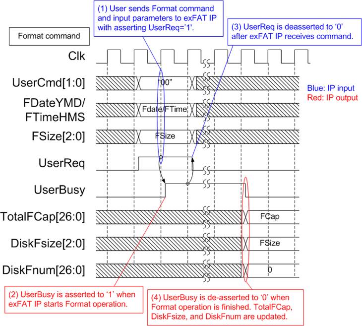
Figure 4: Timing diagram of Format command
The example steps of control interface to run Format command are as follows.
1) User sets UserCmd (“00”), FDate (created date), FTime (created time), and FSize (file size to write in Write file command) with asserting UserReq to ‘1’.
2) exFAT IP asserts UserBusy to ‘1’ and starts Format command operation following the input parameters.
3) UserReq is de-asserted to ‘0’ to complete the current request. Then, user logic waits until Format operation is finished by monitoring UserBusy.
4) UserBusy is de-asserted to ‘0’ after finishing to create file system information and 512 empty directories (DIR000 – DIR1FF) in the device. TotalFCap (maximum files in the device), DiskFsize (file size setting in the device), and DiskFnum (total available files in the device) are updated. DiskFsize is equal to Fsize during Format command request while DiskFnum is reset to 0 to show empty status on the device. Created date and created time of empty directory are equal to FDataYMD and FTimeHMS input.
Write File command
To operate Write file command, user must set the input parameters of Write file command to control interface of exFAT IP. After that, data is read from user logic by exFAT IP through data interface.

Figure 5: Timing diagram of control interface during Write file command
The example steps of control interface to run Write file command are as follows.
1) User sets UserCmd (“10”), FDate (created date), FTime (created time), UserFName (Start file name to write), and UserFLen (total write file) with asserting UserReq to ‘1’. UserFName should be equal to DiskFnum. UserFName + UserFLen must be less than or equal to TotalFCap. In the example, UserFName is equal to 0 for the 1st Write file command to empty device.
Note: If the new file name is more than DiskFnum, the new file will not be found in the device.
2) exFAT IP asserts UserBusy to ‘1’ and starts Write file command operation by using the input parameters.
3) UserReq is de-asserted to ‘0’ to complete the current request. Then, user logic waits until Write file operation is finished by monitoring UserBusy. In this step, the data interface of exFAT IP forwards total data from user logic to SATA HCTL IP.
4) UserBusy is de-asserted to ‘0’ after finishing forwarding total data. DiskFnum is updated to be equal to UserFName + UserFLen. Created date and created time of the new file are equal to FDataYMD and FTimeHMS input.
5) UserFName of the next Write file command should be equal to DiskFnum which has been updated from the previous Write file command. FDate and FTime of the new Write file command can be changed.
6) DiskFnum is increased to show total available file in the device after complete Write file command. In the example, the last value of DiskFnum is equal to N1 (UserFLen of the 1st Write file command) + N2 (UserFLen of the 2nd Write file command).
Assumed that N1+N2 is less than DirCap (one directory can store all new files in the 1st and 2nd Write file command), the new file in the device is created following Figure 6. The 1st file name is 0000000.BIN and the last file name is (N1 + N2).BIN. Total digits of file name is fixed to 7, so 0 digit is filled as a prefix of filename in the device.

Figure 6: New file is created in the device after finishing Write file command
After exFAT IP receives Write file command request from user, the next process is data transferring from user logic to SATA HCTL IP.
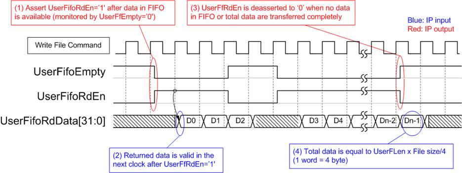
Figure 7: TX FIFO Interface for Write file command
Figure 7 shows timing diagram of data interface during Write file command operation. UserFifoEmpty is monitored by exFAT IP to check data available in Tx FIFO. When data is available (UserFifoEmpty=’0’), UserFifoRdEn is asserted to ‘1’. UserFifoRdData is valid in the next clock after UserFifoRdEn=’1’. After total data are transferred, UserFifoRdEn is de-asserted to ‘0’. Total data size depends on UserFLen input and File size. If UserFLen = N1, total data in 32 bit unit will be equal to N1 x (File size in byte unit / 4).
Read File command
To operate Read file command, user must set the input parameters of Read file command to the control interface of exFAT IP. Comparing to other commands, Read File command uses only UserFName and UserFLen to be input parameters. After that, data is sent by exFAT IP to user logic through the data interface.
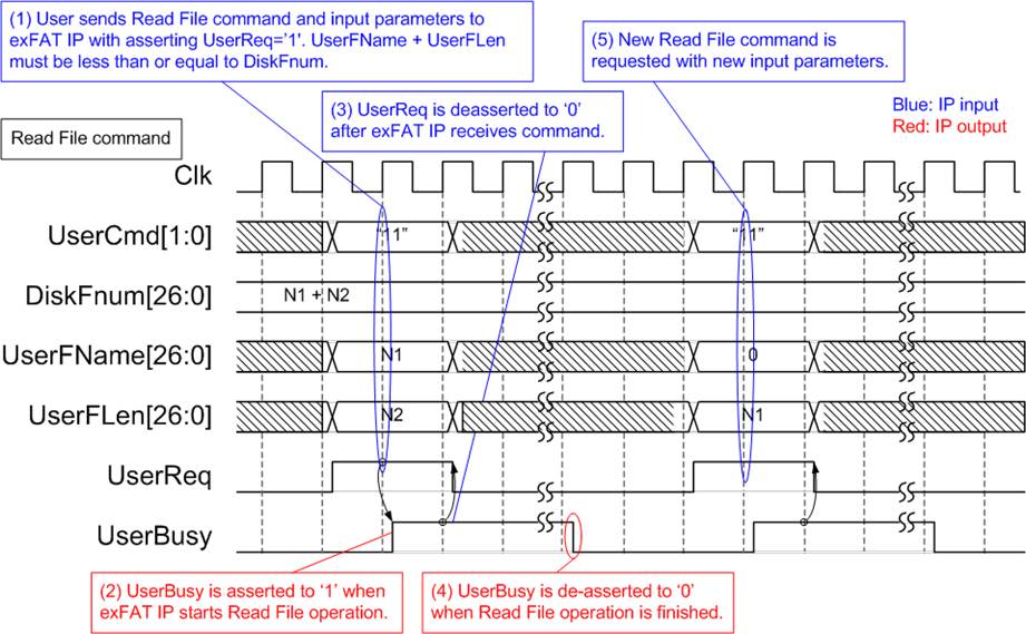
Figure 8: Timing diagram of control interface during Read file command
The example steps of control interface to run Read file command are as follows.
1) User sets UserCmd (“11”), UserFName (Start file name to read), and UserFLen (total read file) with asserting UserReq to ‘1’. The caution point is UserFName + UserFLen must be less than or equal to DiskFnum (total available file in the device).
2) exFAT IP asserts UserBusy to ‘1’ and starts Read file command operation by using the input parameters.
3) UserReq is de-asserted to ‘0’ to complete the current request. Then, user logic waits until Read file operation is finished by monitoring UserBusy. In this step, the data interface of exFAT IP forwards total data from SATA HCTL IP to user logic.
4) UserBusy is de-asserted to ‘0’ after finishing forwarding total data. DiskFnum is stable during Read file operation.
5) The new command request could be sent to exFAT IP.
Data interface to transfer data from the device to user logic is displayed on Figure 9

Figure 9: RX FIFO Interface for Read file command
For Read file command, UserFifoWrEn is asserted to ‘1’ with the valid value of UserFifoWrData to send data to Rx FIFO.
1) Before asserting UserFifoWrEn, UserFifoWrCnt is monitored to check free space size of Rx FIFO. Data is transferred when free space in Rx FIFO is more than 7 dwords (UserFfWrCnt[15:3] is not equal to all one).
2) When UserFfWrCnt[15:3] is equal to all one, UserFifoWrEn must be deasserted to ‘0’ to pause data transferring within 7 clock cycles. Also, UserFifoWrEn is also deasserted to ‘0’ when total data are completely transferred.
Similar to Write file command, total data is equal to UserFLen x (File size in byte unit / 4).
Error
UserError is asserted to ‘1’ by error condition within SATA HCTL IP or exFAT IP. More details of error status are defined in UserErrorType. To clear Error flag, user needs to send reset signal (RstB=’0’) to exFAT IP and HCTL IP.
After complete above sequence, exFAT IP is ready to receive the command from user.
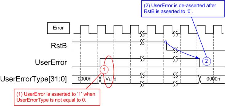
Figure 10: Error flag timing diagram
Limitation
(1) SATA device which is connected to exFAT IP must be formatted by exFAT IP. The maloperation will be happened such as wrong device information (TotalFCap, DiskFsize, and DiskFnum) if the device is not formatted by exFAT IP.
(2) All files in SATA device must be written by exFAT IP. The maloperation will be happened in the system if the device includes some files which is written by the other hosts.
(3) The other hosts can access SATA device as read-only mode.
(4) All files in SATA device have the same size which is defined by FSize during Format command. To change FSize value, the device must be formatted again with new FSize value.
(5) Table 3 shows the maximum number of files to store in one directory which depends on device capacity. The equation to calculate directory name from filename is as follows.
DIR Name = (<FileName>/DirCap) – 1
Assumed that device capacity is 100 GB, DirCap (the maximum file in one directory) is equal to 512. 0000000.BIN – 000001FF.BIN are stored to DIR000.
0000200.BIN – 000003FF.BIN are stored to DIR001.
0000400.BIN – 000005FF.BIN are stored to DIR002.
0000600.BIN – 000007FF.BIN are stored to DIR003.
0000800.BIN – 000009FF.BIN are stored to DIR004.
0000A00.BIN – 00000BFF.BIN are stored to DIR005.
0000C00.BIN – 00000DFF.BIN are stored to DIR006.
0000E00.BIN – 00000FFF.BIN are stored to DIR007.
DIR008 – DIR1FF are empty directories.
(6) In Write file command, UserFName input should be equal to DiskFnum.
a) If UserFName is more than DiskFnum, it will be the error condition. After running by this condition, the new file is not found in the device. Also, DiskFnum value is not correct.
b) If UserFName is less than DiskFnum, the old file will be overwritten by the new data. DiskFnum will be not change if the sum of UserFName and UserFlen in the new write request is less than the current value of DiskFnum. DiskFnum to show total file in SATA device is not reduced without running Format command.
Verification Methods
The exFAT IP Core for SATA functionality was verified by simulation and also proved on real board design by using Arria10 SoC/Cyclone10 GX development board.
Recommended Design Experience
Experience design engineers with a knowledge of QuartusII Tools should easily integrate this IP into their design.
Ordering Information
This product is available directly from Design Gateway Co., Ltd. Please contact Design Gatway Co., Ltd. for pricing and additional information about this product using the contact information on the front page of this datasheet.
Revision History
|
Revision |
Date |
Description |
|
1.0 |
Nov-28-2018 |
New release |
|
1.1 |
Mar-20-2019 |
Add DiskFsize and DiskFnum input |
|
1.2 |
May-09-2019 |
Update the maximum number of file per directory |