SATA AHCI-IP Demo on V/10-series SoC Instruction
Rev1.2 22-Aug-23
2.2 FPGA board setup to run the demo
5.1 Performance test by diskTestApp
This document describes the instruction to run SATA AHCI-IP on Altera development board, i.e. CycloneV SX SoC, ArriaV ST SoC, and Arria10 SoC development Board. From device limitation, CycloneV SX SoC board can support only SATA-II device while other boards can support SATA-III device. This demo uses Angstrom linux v2014.12 OS, and FPGA can boot and be configured by micro SD Card.
1 Hardware Requirement
As shown in Figure 1‑1- Figure 1‑3, to run AHCI demo please prepare
1) CycloneV SX/ArriaV ST/Arria10 SoC Development Board
2) SATA adapter board provided by Design Gateway
- AB11-HSMCSATA board for CycloneV SX SoC
- AB09-FMCRAID board for ArriaV ST/Arria10 SoC
3) 2.5-inch SATA-II/III Device or other size with adapter cable
- SATA-II for CycloneV SX
- SATA-III for ArriaV ST/Arria10 SoC
4) Micro SD card with SD card image, downloaded from
http://www.dgway.com/SATA-IP_A_E.html
5) Mini USB cable
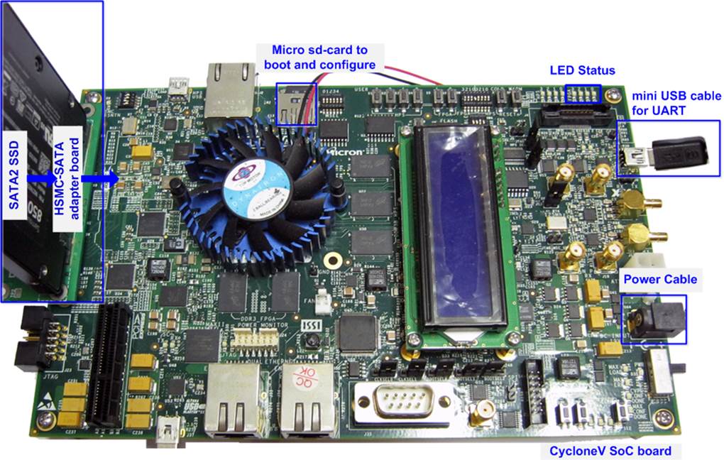
Figure 1‑1 SATA AHCI-IP Demo Environment Setup on Cyclone V SX SoC board
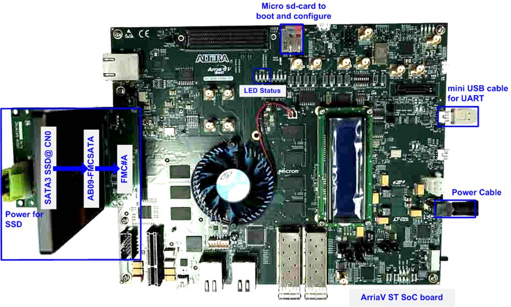
Figure 1‑2 SATA AHCI-IP Demo Environment Setup on Arria V ST SoC board
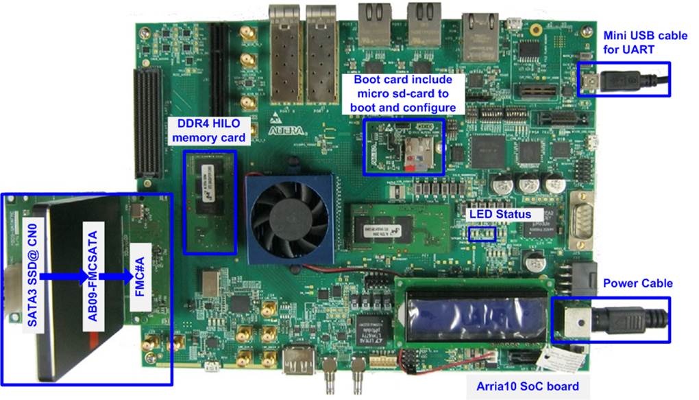
Figure 1‑3 SATA AHCI-IP Demo Environment Setup on Arria 10 SoC board
2 Hardware setup
2.1 Micro SD Card setup by PC
· Extract �sd_card_image_cyclone5/arria5/arria10.bin.tar.gz�, and file output will be
�sd_card_image_cyclone5/arria5/arria10.bin�.
· Connect microSD to PC to dump image to card by using �Win32DiskImager� application.
· Run �Win32DiskImager� to copy �sd_card_image_cyclone5/arria5/arria10.bin� to microSD, as shown in Figure 2‑1.
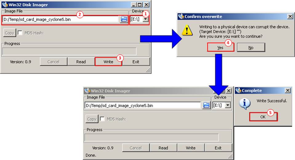
Figure 2‑1 Create SD Card Image for SATA AHCI-IP Demo
(1) Select drive to microSD card drive
(2) Browse to the path which store �sd_card_image_cyclone5/arria5/arria10.bin�
(3) Click �Write� to start dump data.
(4) �Confirm overwrite� window will be displayed. Click �Yes� to confirm data dump.
(5) Wait until progress status updated from 0% to 100%. �Complete window� with �Write Successful� will be displayed. Click �OK� to complete this step.
2.2 FPGA board setup to run the demo
· Power off FPGA board and adapter board.
· Insert micro SD card to SD card socket
· Connect HDD/SSD to SATA socket on CN0 @ HSMC/FMC SATA adapter board.
a) For Cyclone V SoC board, insert SATA-II HDD/SSD
b) For other boards, insert SATA-III HDD/SSD
· For FMC adapter board, connect power to power connector on FMCRAID board.
· Connect SATA adapter board to FPGA board.
Note: If FPGA board has FMC/HSMC port more than one, use port#A.
· Connect USB mini cable between FPGA board and PC for UART
· Set JTAG enable
a) For CycloneV SX and ArriaV ST SoC, set SW4[1]/[2]/[4] = OFF position to enable JTAG of HPS, FPGA, and MAX, as shown in Figure 2‑2
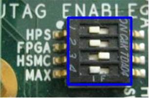
Figure 2‑2 JTAG Enable for CycloneV SX/ArriaV ST SoC board
b) For Arria10 SoC, set SW3[1]/[2]/[6]/[8] = OFF position to enable JTAG of HPS, FPGA, and MAX, as shown in Figure 2‑3
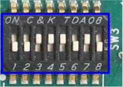
Figure 2‑3 JTAG Enable for Arria10 SoC board
· Enable clock programmable for CycloneV SX SoC board. Set bit2 of SW2 to ON position, as shown in Figure 2‑4.
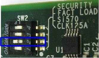
Figure 2‑4 SW2 Enable Si570 clock source
· Set FPGA configuration by HPS for Arria10 SoC board. Set SW4[2]-[4] to OFF position, as shown in Figure 2‑5.
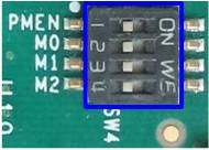
Figure 2‑5 SW4 Configuration Mode
· Power on FPGA board.
· Open serial monitoring software such as HyperTerminal. Terminal settings is Baud Rate=115,200, Data=8 bit, Non-Parity, and Stop=1.
· On PC serial console, please wait Linux boot-up until login required, as shown in Figure 2‑6.
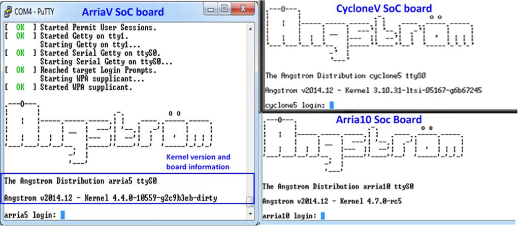
Figure 2‑6 Linux Bootup
· Power on supply on adapter board
a) For HSMC adapter of CycloneV SX, ON power-switch on HSMC adapter after Linux boot up completely.
Note: Do not on power-switch before linux boot-up complete. It needs to wait linux to program clock for SATA to be 150 MHz before SATA AHCI-IP communicates with SATA Device.
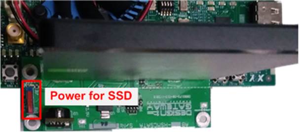
Figure 2‑7 Power for SSD on HSMC adapter
b) For FMC adapter, ON power supply which is connected to power connector on the adapter, as shown in Figure 2‑8.
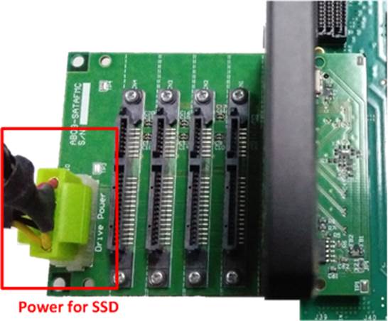
Figure 2‑8 Power for SSD on FMC Adapter
· Check LED status on FPGA board now and LED0-1 will turn on while LED2 status depends on SATA speed, as shown in Figure 2‑9.
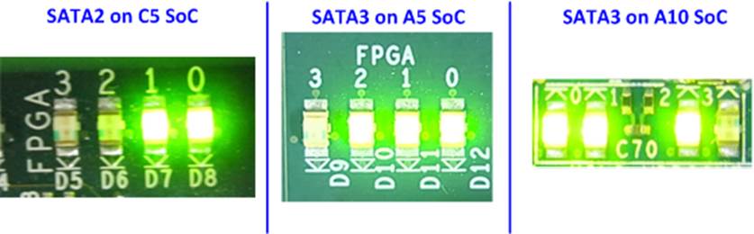
Figure 2‑9 LED status after system set up complete on SATA-3/2 speed
|
LED |
ON |
OFF |
|
LED0 |
OK |
TXPLL inside transceiver cannot lock the clock. Please check 150 MHz clock source. |
|
LED1 |
OK |
SATA-IP cannot detect SATA device. Please check SATA device and the connection. |
|
LED2 |
SATA-III for others |
SATA-II for CycloneV SX SoC |
|
LED3 |
SATA AHCI-IP in processing |
SATA AHCI-IP in idle |
Table 2‑1 LED Status of AHCI reference design
3 Linux Setup
· User login on the demo is follows.
Login : root
Password : root (required for ArriaV only)
After login, system is ready to receive user command, as shown in Figure 3‑1.
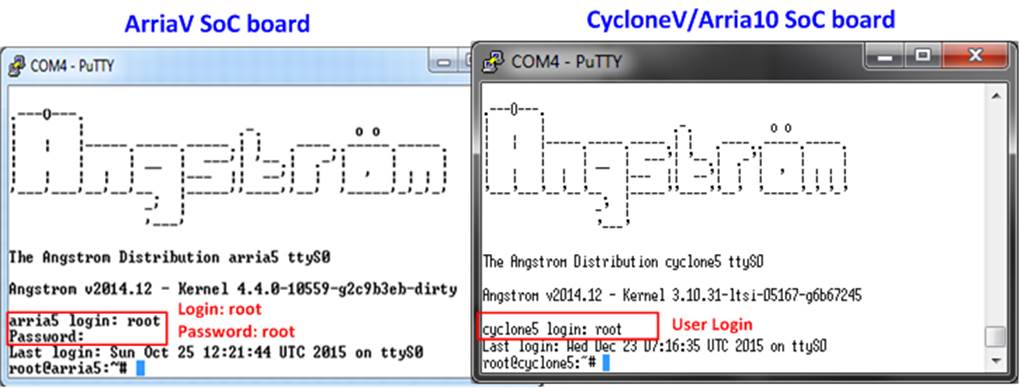
Figure 3‑1 Linux Login
· To run SATA AHCI-IP demo,
- For CycloneV SX SoC board, two modules are required to insert, i.e libahci.ko (common AHCI SATA low-level routines) and dg_ahciDemo.ko (AHCI SATA platform driver).
- For other boards, libahci_platform.ko is also required to be AHCI SATA platform library. So, three modules are required to insert.
All modules are stored in �/home/root/driver� directory. To insert module, please use following command.
>> insmod dg_ahciDemo/driver/libahci.ko
>> insmod dg_ahciDemo/driver/libahci_platform.ko
(Not used for CycloneV SX SoC board)
>> insmod dg_ahciDemo/driver/dg_ahciDemo.ko
· After insert modules, disk information will be displayed, as shown in Figure 3‑2. Now SATA device is ready to use.
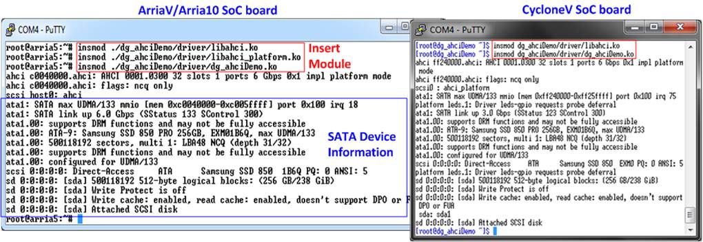
Figure 3‑2 Insert module to linux kernel
4 Example Linux command
4.1 Create Disk Partition
To create new disk partition, user can follow below steps.
>> fdisk /dev/sda
Call the tool to manage disk partition.
>> n
Create new partition.
>> p
Select primary partition.
Select the option by using default value in the tool such as partition number = 1, first cylinder=1, last cylinder=31130.
>> w
Write table to the disk.
Now one partition named sda1 has been created in the disk.
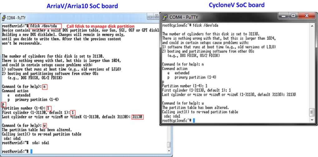
Figure 4‑1 fdisk command
Note: User can type �m� to show all fdisk options.
4.2 Format Disk
To format the disk, user needs to select file system type such as FAT, EXT4. This example shows only the command to format to EXT4 by typing following command.
>> mkfs.ext4 /dev/sda1
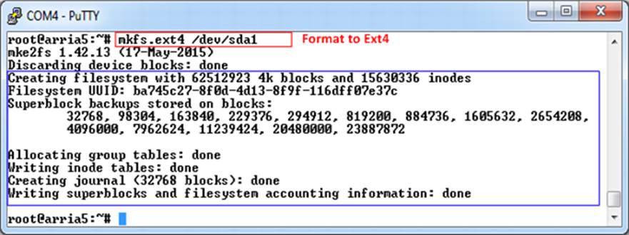
Figure 4‑2 Format disk
4.3 Mount Disk
Before running any application to access the disk by file system such as Bonnie++ and diskTestApp in file system mode, disk must be mounted firstly by following command.
>> mount /dev/sda1 /media/hdd
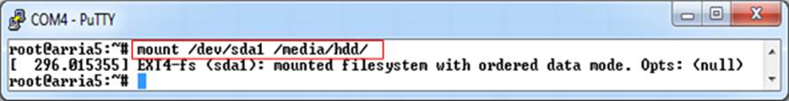
Figure 4‑3 Mount disk
5 Performance test
This topic shows the example application to test disk performance. Two test applications are used, i.e. diskTestApp and Bonnie++. diskTestApp is the test application developed by Design Gateway to check write/read performance in both raw data format and file system.
5.1 Performance test by diskTestApp
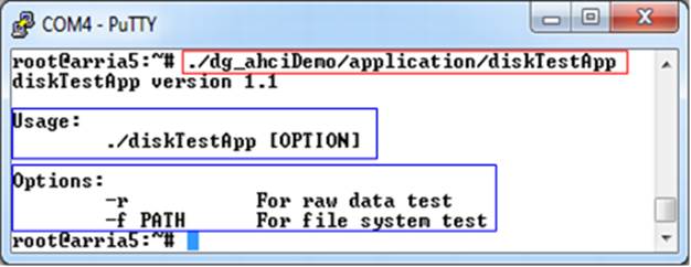
Figure 5‑1 diskTestApp usage
As shown in Figure 5‑1, diskTestApp can run in two data formats, i.e. raw data or file system.
Warning: If running raw data test, file system in that disk partition will be lost.
5.1.1 Raw Data Mode
Type command �./dg_ahciDemo/application/diskTestApp �r� to run test application in raw data format. Five input parameters are required, i.e.
1) Disk selection to select the disk to test performance
2) Operation type: �0�-Read disk test, �1�-Write disk test
3) Test pattern:
�0�: Write by dummy data or read without verification
�1�: Write or verify by 32-bit increment pattern
�2�: Write or verify by 32-bit decrement pattern
4) Disk offset: Disk start address in sector unit to write/read data. 0x prefix is added for hex unit input while default value without prefix is decimal unit.
5) Operation length: Transfer length in sector unit to write/read data. 0x prefix is added for hex unit input while default value without prefix is decimal unit.
Figure 5‑2 and Figure 5‑3 show the example of write test in raw data mode by dummy data and increment data. Figure 5‑4 and Figure 5‑5 show the example of read test in raw data mode without and with data verification. Comparing to increment/decrement pattern, using dummy mode for both write and read will achieve better performance because CPU resource is not used to fill or verify the data.
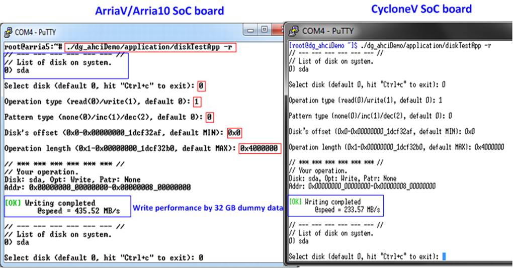
Figure 5‑2 Write performance in raw data mode by dummy data
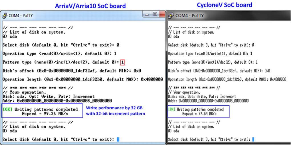
Figure 5‑3 Write performance in raw data mode by 32-bit increment data
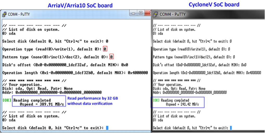
Figure 5‑4 Read performance in raw data mode without data verification
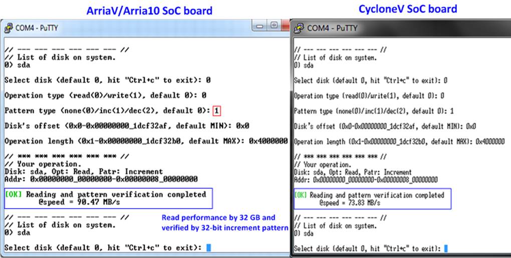
Figure 5‑5 Read performance in raw data mode and verify by 32-bit increment data
5.1.2 File System Mode
Before run test application in File system mode, user needs to create disk partition, format disk, and mount the disk.
Type �./dg_ahciDemo/application/diskTestApp �f /media/hdd� to run the test in file system mode. Five input parameters are required, i.e.
1) File name input: File name to run the test
2) Operation type: �0�-Read file test, �1�-Write file test
3) Test pattern:
�0�: Write by dummy data or read without verification
�1�: Write or verify by 32-bit increment pattern
�2�: Write or verify by 32-bit decrement pattern
4) File number: Total number of files to run write/read file test
5) File size: Size of each file in sector unit to run write/read file test
Similar to raw data mode, when write by dummy pattern or read without data verification, performance will be better than increment/decrement pattern, as shown in Figure 5‑6 - Figure 5‑9.
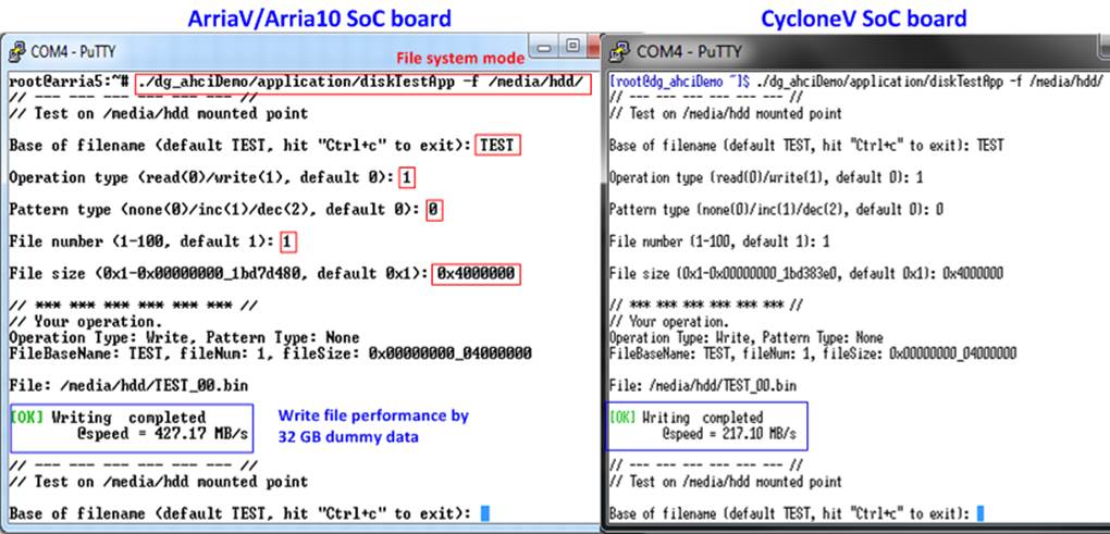
Figure 5‑6 Write file performance by dummy data
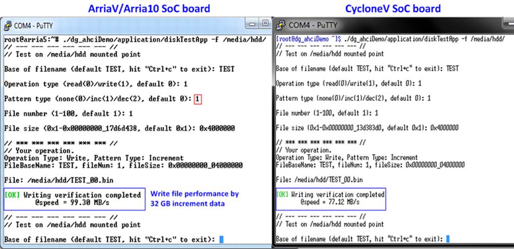
Figure 5‑7 Write file performance by 32-bit increment data
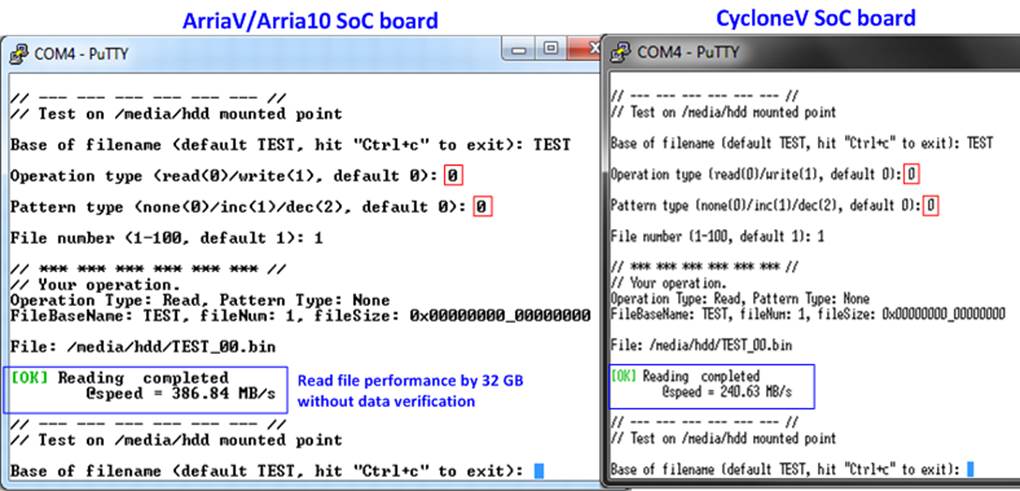
Figure 5‑8 Read file performance without data verification
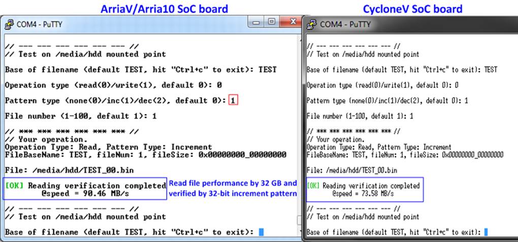
Figure 5‑9 Read file performance and verify by 32-bit increment data
5.2 Bonnie++ Software
This topic shows how to test disk performance by using Bonnie++ software. The brief option of Bonnie++ software is belows.
![Text Box: bonnie++ [-d dir] [-s size(MB)[:chunk-size(b)]] [-n number-to-stat(*1024) [:max-size[:min-size] [:num-directories]]] [-m machine-name] [-r ram-size-in-MB] [-x number-of-tests] [-u uid-to-use:gid-to-use] [-g gid-to-use] [-q] [-f size-for-char-io] [-b] [-D] [-p processes | -y p|s] [-z seed-num|-Z random-file]](dg_sataahciip_instruction_altera_en_files/image027.gif)
More details about Bonnie++ user manual can be found from http://linux.die.net/man/8/bonnie++.
The example command to run Bonnie++ is follows.
>> bonnie++ -d /media/hdd/ -s 2g -n 0 -m test -f -u root
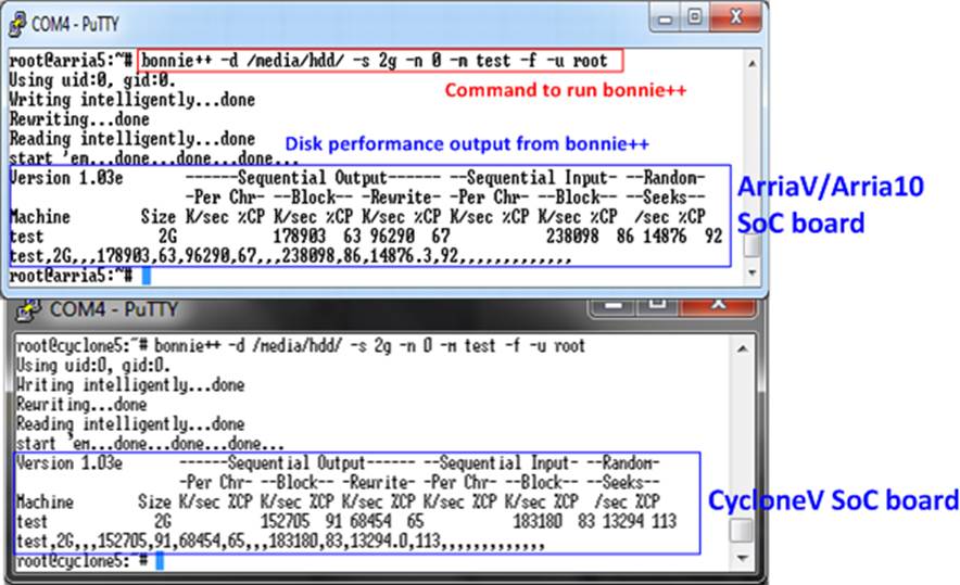
Figure 5‑10 Test performance from Bonnie++ benchmark
6 Revision History
|
Revision |
Date |
Description |
|
1.0 |
11-Jan-16 |
Initial version release |
|
1.1 |
3-Mar-16 |
Support ArriaV SoC board |
|
1.2 |
1-Aug-16 |
Support Arria10 SoC board |
Copyright: 2016 Design Gateway Co,Ltd.