2.7 Xilinx Transceiver (PMA for 10GBASE-R)
1 Introduction
This document describes the details of TLS 1.3 Server 10Gbps IP Core (TLS10GS-IP) reference design. In this reference design, TLS10GS-IP is used to establish a secure connection using the Transport Layer Security protocol version 1.3 over TCP by handling TLS1.3 handshake, encrypting and decrypting data transferred between the client and the server. Users can set network parameters for TOE10GLL-IP, transmit and receive payloads corresponding to supported request from the client. Further details of the hardware design and CPU firmware are provided below.
2 Hardware Overview
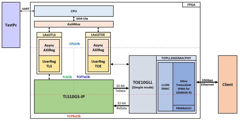
Figure 2‑1 TLS10GS-IP reference design block diagram
In this test environment, CPU system is designed to interface with FPGA logic through AXI4 Lite bus and interface with user through serial console in test PC. CPU system communicates with hardware via memory mapping. Axi4Mux is designed to separate the memory mapping for hardware communication into two areas, offset 0x00000-0x000FF for TOE10GLL-IP and 0x00100-0x3FFFF for TLS10GS-IP. To connect the hardware with each memory area of CPU system, AXI4-Lite bus must be implemented by LAxi2TLS for TLS10GS-IP and LAxi2TOE for TOE10GLL-IP, as shown in Figure 2‑1.
There are four clock system in this reference design, i.e., CPUClk, TLSClk, TCPTxClk and TCPRxClk. CpuClk is used to interface with CPU through AXI4-Lite bus. TLSClk is the clock domain on which TLS10GS-IP operates and interface with user. TCPTxClk is the clock domain which is synchronous to Tx EMAC interface and Tx user data interface. TCPRxClk is the clock domain which is synchronous to Rx EMAC interface and Rx user data interface.
The details of each module are described as follows.
2.1 AsyncAxiReg
This module is designed to convert the signal interface of AXI4-Lite to be register interface. Also, it enables two clock domains to communicate.
To write register, RegWrEn is asserted to ‘1’ with the valid signal of RegAddr (Register address in 32-bit unit), RegWrData (write data of the register), and RegWrByteEn (the byte enable of this access: bit[0] is write enable for RegWrData[7:0], bit[1] is used for RegWrData[15:8], …, and bit[3] is used for RegWrData[31:24]).
To read register, AsyncAxiReg asserts RegRdReq=’1’ with the valid value of RegAddr (the register address in 32-bit unit). After that, the module waits until RegRdValid is asserted to ‘1’ to get the read data through RegRdData signal at the same clock.
2.2 LAxi2TLS
LAxi2TLS module is connected to CPU through AXI4-Lite bus. The hardware registers for TLS10GS-IP are mapped to CPU memory address, as shown in Table 2‑1. The control and status registers for CPU access are designed in LAxi2TLS.
LAxi2TLS consists of AsyncAxiReg and UserRegTLS. AsyncAxiReg is designed to convert the AXI4-Lite signals into a simple register interface with 32-bit data bus size (similar to AXI4-Lite data bus size).
UserRegTLS is connected to TLS10GS-IP to control, monitor and prepare data for TLS10GS-IP operation. UserRegTLS consists of register file, two dual port rams for storing certificate and RSA key information (CertRam and RSAKeyRam), a data pattern generator (UserDataGen) and a data pattern verification (UserDataVer), as shown in Figure 2‑2.
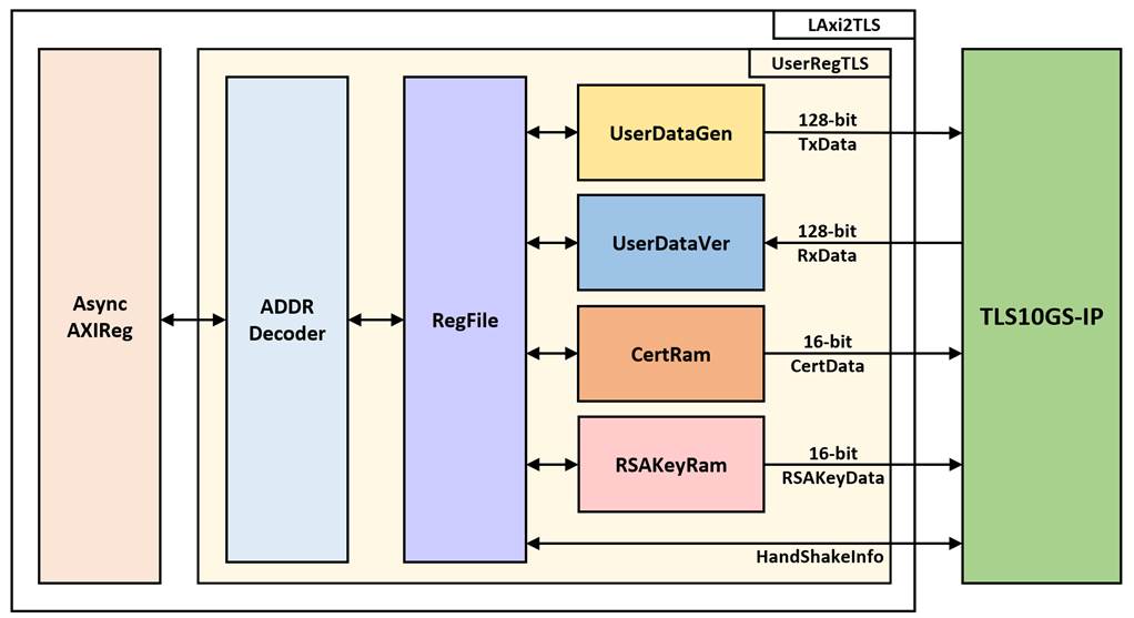
Figure 2‑2 UserRegTLS block diagram
Register file
For register file, UserRegTLS is designed to write/read registers, control and check alert of TLS10GS-IP corresponding with write register access or read register request from AsyncAvlReg module. The memory map inside UserRegTLS module is shown in Table 2‑1. The timing diagram of register interface is shown in Figure 2‑3.
Table 2‑1 Register map Definition of TLS10GS-IP
|
Address offset |
Register Name |
Rd/Wr |
Description |
|
0x00100 |
TLS_RSTB_REG |
Wr |
[0]: Reset signal active low (TLSRstB). |
|
0x00104 |
TLS_BUSY_REG |
Rd |
[1]: Busy status for
handshake operation (TLSHandshakeBusy). |
|
0x00108 |
TLS_ALERT_REG |
Rd |
[15:0]: Alert code from TLS10GS-IP (TLSAlertCode[15:0]) |
|
0x0010C |
TLS_TIMEOUT_REG |
Wr |
[15:0]: Timeout value for waiting returned packet (TLSTimeOut[15:0]) |
|
0x00110 |
TLS_TX_RDPTR_REG |
Rd |
[13:0]: Read pointer to indicate the first byte position of TxData that IP will process (TLSTxUserRdPtr). |
|
0x00114 |
TLS_TX_WRPTR_REG |
Wr |
[13:0]: Write pointer to indicate the position after the last TxData written (TLSTxUserWrPtr). |
|
0x00118 |
TLS_RX_RDPTR_REG |
Wr |
[13:0]: Read pointer to indicate the first byte of RxData that user already to process (TLSRxUserRdPtr). |
|
0x0011C |
TLS_RX_WRPTR_REG |
Rd |
[13:0]: Write pointer to indicate the position after the last RxData written (TLSTxUserWrPtr). |
|
0x00120 |
USER_TX_PATT_TYPE_REG |
Wr |
[1:0]: Data Pattern Mode (rPattGenMode) “00”, “01”, “10” and “11” for decreasing binary, increasing binary, decreasing text, and increasing text, respectively. |
|
0x00124 |
USER_TX_PATT_LEN_REG |
Rd |
[31:0]: Remaining data pattern length (wPattRemainLen[31:0]) |
|
Wr |
[31:0]: Data pattern length (rPattGenLen[31:0]) |
||
|
0x00128 |
USER_RX_VERIFY_TYPE_REG |
Rd |
[1]: Status of Data pattern verification
(wVerifyBusy) |
|
Wr |
[1]: Verify Pattern Mode (rVerifyMode) “00”, “01”, “10” and “11” for decreasing binary, increasing binary, decreasing text, and increasing text, respectively. |
||
|
USER_RX_VERIFY_LEN_REG |
Rd |
[31:0]: Remaining verify length (wDataRemainLen[31:0]) |
|
|
Wr |
[31:0]: Verify pattern length (rVerifyDataLen[31:0]) |
||
|
0x00130 |
HTTPHEADER_LEN_REG |
Wr |
[13:0]: Number of bytes for skipping HTTP header before verification. (rHttpHeaderLen) |
|
0x00134 |
HTTPTRAILER_LEN_REG |
Wr |
[13:0]: Number of bytes for skipping HTTP trailer before verification. (rHttpTrailerLen) |
|
0x00140-0x0014C |
USER_RX_ACTUAL_DATA |
Rd |
[31:0]: Actual RxData (wActualData[127:0]) |
|
0x00150-0x0015C |
USER_RX_EXP_DATA |
Rd |
[31:0]: Expected RxData (wExpData[127:0]) |
|
0x00200-0x0022C |
CTS_REG |
Rd |
[31:0]: Client Traffic Secret (CTS) |
|
0x00230-0x0025C |
STS_REG |
Rd |
[31:0]: Server Traffic Secret (STS) |
|
0x00260 |
TLS_KEYVALID_REG |
Rd |
[0]: Validity status for key material, key and iv (TLSKeyValid) |
|
0x00270-0x0028C |
CH_RANDOM_REG |
Rd |
[31:0]: Random number in ClientHello message. (Random[255:0]) |
|
0x003FC |
TLS_VER_REG |
Rd |
[31:0]: Mapped to IP version of TLS10GS-IP (version) |
|
0x14000-0x15FFF |
CERTRAM_BASE_ADDR |
Rd/Wr |
[31:0]: Certificate data in CertRam (wRamCertRdData) |
|
0x16000-0x167FF |
RSAKeyRAM_BASE_ADDR |
Rd/Wr |
[31:0] RSA key data in RSAKeyRam (wRamRSAKeyRdData) |
|
0x20000-0x23FFF |
RXRAM_BASE_ADDR |
Rd |
[31:0]: Rx data in UserRxBuffer (wRxRdData32) |
|
0x30000-0x33FFF |
TXRAM_BASE_ADDR |
Wr |
[31:0]: Tx data in UserTxBuffer |
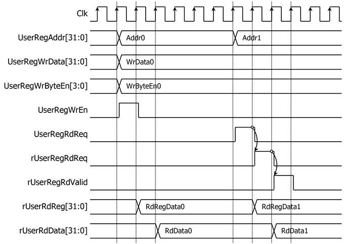
Figure 2‑3 Register interface timing diagram
To read register, the multiplexer is designed to select the read data within each address area. UserRegAddr[13:2] is applied in each register area to select the data. Next, the address decoder uses UserRegAddr[17:16] to select the read data from each area for returning to CPU. As shown in Figure 2‑3, read data is valid in next two clock cycles. When UserRegRdReq is active, rUserRegRdReq is asserted to ‘1’. Then rUserRdValid is active with the valid read value of UserRegAddr.
To write register, UserRegWrEn is asserted to ‘1’ with the valid of UserRegAddr. UserRegAddr[17:16] is used to decode whether CPU accesses UserTxBuffer of TLS10GS-IP or the internal register area. The CPU can access UserTxBuffer when UserDataGen is not busy (rPattGenBusy=’0’). When the CPU accesses UserTxBuffer (UserRegAddr[17:16]=“11”), UserRegAddr[15:4] is set to TLSTxUserAddr[15:4]. For example, when UserRegAddr[17:0]= 0x1C004 and UserRegWrEn=’1’, UserTxBuffer in TLS10GS-IP will be filled with UserRegWrData at Address 0x01. Otherwise, UserRegWrData is loaded into the internal register that matches UserRegAddr[13:2]. For example, rTLSRstBOut is loaded with UserRegWrData when UserRegAddr=0x0000.
Certificate and RSA key information
TLS10GS-IP is designed to read certificate and RSA key information from the user via Ram interface. In this reference design, dual port ram (CertRam) is used to store the certificate information. As shown in Figure 2‑4, TLSCertRdEn and TLSCertRdAddr[12:1] are used as read enable and read address for CertRam, respectively. When TLSCertRdEn is asserted to ‘1’, TLSCertRdData[15:0] must be valid in the next clock cycle.
In the same way, TLSRSAKeyRdEn and TLSRSAKeyRdAddr[10:1] are used as read enable and read address for RSAKeyRam, respectively. When TLSRSAKeyRdEn is asserted to ‘1’, TLSRSAKeyRdData[15:0] must be valid in the next clock cycle, as shown in Figure 2‑5.
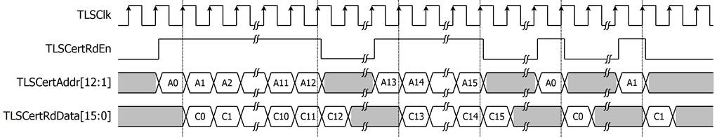
Figure 2‑4 Example timing diagram of reading certificate information
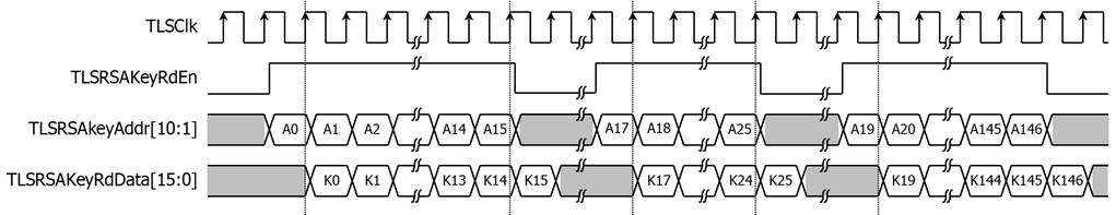
Figure 2‑5 Example timing diagram of reading RSA
key information
User Data Generator
UserDataGen is designed to generate a data pattern and write it to UserTxBuffer. There are four types of data patterns: increasing/decreasing binary pattern, increasing/decreasing text pattern. Users can set the type of data by writing to USER_TX_PATT_TYPE_REG, which is mapped to rPattGenMode signal. UserDataGen supports generating unaligned data. After the user sets the data size in byte units to rPattGenLen by writing to USER_TX_PATT_LEN_REG, the data pattern (TLSTxUserDataIn[127:0]) and TLSTxUserByteEn[15:0] are prepared corresponding to the start address.

Figure 2‑6 Example timing diagram of user data generation process
User Data Verification
UserDataVer reads data via the User Rx interface of TLS10GS-IP when there is available data in UserRxBuffer and verifies the value after starting verification (rVerifyStart is set to ‘1’). There are four types of expected data patterns: increasing/decreasing binary pattern, increasing /decreasing text pattern. Users can set the length of the HTTP header and trailer to skip before starting verification. When there is available data in UserRxBuffer, UserDataVer starts to read received data. UserDataVer supports verifying unaligned data. rExpData[127:0] and rMask[127:0] are prepared corresponding to the start address.
For example, if the start address is 0x1F, and user sets UserDataVer to verify 451-byte increasing text pattern, rExpData[127:120] is set to 0x00 and rMask[127:0] is set to 0xFF000000000000000000000000000000 at the first clock cycle to verify only the highest byte at TLSRxUserAddr[13:0]=0x10. TLSRxUserRdPtr is set to the next start address to indicate to TLS10GS-IP that UserDataVer has already processed RxData. At the second clock cycle, every byte of Rx data is verified. At the last clock cycle, only the last 2 bytes of the data pattern are verified, rMask[127:0] is set to 0x0000000000000000000000000000FFFF and rExpData[15:0] is set to 0xC2C1, as shown in Figure 2‑7.
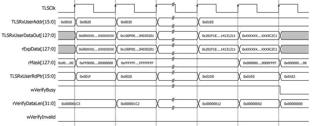
Figure 2‑7 Example timing diagram of user data verification process
2.3 TLS10GS-IP
TLS10GS-IP is the IP core provided by Design Gateway to handle TLS1.3 handshake, encrypt and decrypt data as a server. TLS10GS-IP interface is divided into two parts, i.e., User Interface signals and TOE10GLL interface signals. The user interface is connected to LAxi2TLS, allowing user to control, monitor and transfer data with TLS10GS-IP. TOE10GLL interface is connected to TOE10GLLIP to monitor connection status, send TCPTxData or receive TCPRxData. More details are described in datasheet.
https://dgway.com/products/IP/TLS-IP/TLS10GSIP_datasheet_xilinx_en/
2.4 LAxi2TOE
LAxi2TOE module is connected to CPU through AXI4-Lite bus. LAxi2TOE consists of AsyncAxiReg and UserRegTOE. UserRegTOE is designed to write/read registers, control and check status of TOE10GLLIP corresponding with write register access or read register request from AsyncAvlReg module. Memory map inside UserRegTOE module is shown in Table 2‑2.
Table 2‑2 Register map Definition of TOE10GLLIP
|
Address offset |
Register Name |
Rd/Wr |
Description |
|
0x00000 |
TOE_RST_INTREG |
Wr |
[0]: Mapped to RstB of TOE10GLL-IP |
|
0x00004 |
TOE_OPM_INTREG |
Wr |
[16]: Mapped to ARPICMPEn of TOE10GLL-IP |
|
0x00008 |
TOE_SML_INTREG |
Wr |
[31:0]: Mapped to SrcMacAddr[31:0] of TOE10GLL-IP |
|
0x0000C |
TOE_SMH_INTREG |
Wr |
[15:0]: Mapped to SrcMacAddr[47:32] of TOE10GLL-IP |
|
0x00010 |
TOE_DMIL_INTREG |
Wr |
[31:0]: Mapped to DstMacAddr[31:0] of TOE10GLL-IP |
|
0x00014 |
TOE_DMIH_INTREG |
Wr |
[15:0]: Mapped to DstMacAddr[47:32] of TOE10GLL-IP |
|
0x00018 |
TOE_SIP_INTREG |
Wr |
[31:0]: Mapped to SrcIPAddr of TOE10GLL-IP |
|
0x0001C |
TOE_DIP_INTREG |
Wr |
[31:0]: Mapped to DstIPAddr of TOE10GLL-IP |
|
0x00020 |
TOE_TMO_INTREG |
Wr |
[31:0]: Mapped to TimeOutSet of TOE10GLL-IP |
|
0x00024 |
TOE_TIC_INTREG |
Wr |
[0]: Set ‘1’ to clear read value of TOE_STS_INTREG[2] |
|
0x00030 |
TOE_CMD_INTREG |
Wr |
[1:0]: Mapped to TCPCmd of TOE10GLL-IP. |
|
0x00034 |
TOE_SPN_INTREG |
Wr |
[15:0]: Mapped to TCPSrcPort[15:0] of TOE10GLL-IP |
|
0x00038 |
TOE_DPN_INTREG |
Wr |
[15:0]: Mapped to TCPDstPort[15:0] of TOE10GLL-IP |
|
0x00040 |
TOE_VER_INTREG |
Rd |
[31:0]: Mapped to IP version of TOE10GLL-IP |
|
0x00044 |
TOE_STS_INTREG |
Rd |
[20:16]: Mapped to IPState of
TOE10GLL-IP |
|
0x00048 |
TOE_INT_INTREG |
Rd |
[31:0]: Mapped to IntStatus of TOE10GLL-IP |
|
0x0004C |
TOE_DMOL_INTREG |
Rd |
[31:0]: Mapped to DstMacAddrOut[31:0] |
|
0x00050 |
TOE_DMOH_INTREG |
Rd |
[15:0]: Mapped to DstMacAddrOut[47:32] |
|
0x00060 |
EMAC_VER_INTREG |
Rd |
[31:0]: Mapped to IP version of DG LL10GEMAC-IP |
|
0x00064 |
EMAC_STS_INTREG |
Rd |
[0]: Mapped to Linkup of LL10GEMAC-IP |
2.5 TOE10GLL
TOE10GLL-IP is the IP core provided by Design Gateway to implement the TCP/IP stack and offload engine for the low latency solution. User interface has two signal groups, i.e., control signals and data signals. The IP can be configured to run in two modes, i.e., Cut-through mode for low-latency application and Simple mode for simple user interface. This reference design shows the usage in Simple mode. More details are described in datasheet.
https://dgway.com/products/IP/Lowlatency-IP/dg_toe10gllip_data_sheet_xilinx_en/
2.6 LL10GEMAC
The IP core by Design Gateway implements low-latency EMAC and PCS logic for 10Gb Ethernet (BASE-R) standard. The user interface is 32-bit AXI4-stream bus. Please see more details from LL10GEMAC datasheet on our website.
https://dgway.com/products/IP/Lowlatency-IP/dg_ll10gemacip_data_sheet_xilinx_en/
2.7 Xilinx Transceiver (PMA for 10GBASE-R)
PMA IP core for 10Gb Ethernet (BASE-R) can be generated by using Vivado IP catalog. In FPGA Transceivers Wizard, the user uses the following settings.
· Transceiver configuration preset : GT-10GBASE-R
· Encoding/Decoding : Raw
· Transmitter Buffer : Bypass
· Receiver Buffer : Bypass
· User/Internal data width : 32
The example of Transceiver wizard in Ultrascale model is described in the following link.
https://www.xilinx.com/products/intellectual-property/ultrascale_transceivers_wizard.html
2.8 PMARstCtrl
When the buffer inside Xilinx Transceiver is bypassed, the user logic must control reset signal of Tx and Rx buffer. The module is designed by state machine to run following step.
(1) Assert Tx reset of the transceiver to ‘1’ for one cycle.
(2) Wait until Tx reset done, output from the transceiver, is asserted to ‘1’.
(3) Finish Tx reset sequence and de-assert Tx reset to allow the user logic beginning Tx operation.
(4) Assert Rx reset to the transceiver.
(5) Wait until Rx reset done is asserted to ‘1’.
(6) Finish Rx reset sequence and de-assert Rx reset to allow the user logic beginning Rx operation.
3 CPU Firmware
After system boot-up, CPU initializes its peripherals such as UART and Timer. Then the supported command usage is displayed. The main function runs in an infinite loop to receive line command input from the user. Users can set the IP address and MAC address of the FPGA board, show key materials, input certificate and RSA key information, start a server to listen for specified client’s IP address on specified server’s port and respond the supported request from a client. More details of the sequence in each command are described as follows.
3.1 Set FPGA’s IP Address
command> setip ddd.ddd.ddd.ddd
All network parameters are set to TOE10GLL-IP. Users can set IP address to TOE10GLL-IP by inputing setip followed by desired IP address in dotted-decimal format. The setip function is called to change IP address value in src_ip_set array. This array will be written to the register mapped to SrcIPAddr to set the FPGA’s IP address. Subsequently, TOE10GLL-IP is initialized with the current network parameter setting. The default FPGA’s IP address is 192.168.7.25. The setip function is described in Table 3‑1.
Table 3‑1 setip function
|
int setip(unsigned char * ipStr, unsigned char *ip_set) |
|
|
Parameter |
ipStr: ip address as string input from user ip_set: array stored IP address |
|
Return value |
0: Valid input, -1: Invalid input |
|
Description |
This function receives IP Address as string input and set value of ip_set array. |
3.2 Set FPGA’s MAC address
command> setmac hh-hh-hh-hh-hh-hh
Users can set MAC address to TOE10GLLIP by inputing setmac followed by the FPGA’s MAC address in hexadecimal format. The setmac function is called to change the MAC address value in mac_set array. This array will be written to the register mapped to SrcMacAddr to set the FPGA’s MAC address. The default FPGA’s MAC address is 00-11-22-33-44-55. The setmac function is described in Table 3‑2.
Table 3‑2 setmac function
|
int setmac(unsigned char *macstr) |
|
|
Parameter |
macstr: MAC address as string input from user |
|
Return value |
0: Valid input, -1: Invalid input |
|
Description |
This function receives MAC Address as string input and set value of mac_set array. |
3.3 Show key materials
command> showkey <1: enable, 0: disable>
To change showkey mode, users can input showkey <1: enable, 0: disable> to modify a global variable, showTrafficSecret. If showTrafficSecret is set to ‘1’, traffic tickets will be displayed on the serial console after the handshake process is completed. Users can use the TLS traffic ticket as a (Pre)-Master-Secret log file for Wireshark* to decrypt transferred data over the current connection.
*Wireshark, a network packet analyzer tool used for network troubleshooting, analysis, and security purposes.
3.4 Set certificate
Command> setcert
Server’s certificate is set by using setcert command. After entering setcert command, the user can send an ASN.1 DER certificate file in binary format, up to 8kB, via the serial connection. The fill_mem_with_wrapper function is called to fill the binary certificate into CertRam. Details about the fill_mem_with_wrapper is described in Table 3‑3. It is essential for users to set the certificate before starting a server.
Table 3‑3 fill_mem_with_wrapper function
|
int fill_mem_with_wrapper (unsigned int *base_addr, unsigned int mem_size8) |
|
|
Parameter |
base_addr: base address of memory to be filled. mem_size8: size of memory to be filled. |
|
Return value |
0: Valid input, -1: Invalid input |
|
Description |
This function writes the binary data from serial console to memory starting at base address. The binary data must not exceed mem_size8. |
3.5 Set RSA key information
Command> setrsakey
RSA private key information is set by using setrsakey command. After entering setrsakey command, the user can send an ASN.1 DER RSA private key file in binary format, up to 2kB, via the serial connection. The fill_mem_with_wrapper function is called to fill the binary RSA key information into RSAKeyRam. It is essential for users to set the RSA key before starting a server.
3.6 Start a server
Command> listenFor ddd.ddd.ddd.ddd on ddddd
Server can be started to listen for a specified client’s IP address on a specified server’s port by using listenFor command. Users can input listenFor with the desired client’s IP address in dotted-decimal format and specify the server’s port (FPGA’s port) in decimal format. listenFor function is called to extract the client’s IP address and the server’s port number, initialize network parameters, process and respond to incoming data corresponding to supported request from the client. The sequence of the listenFor function is as follows.
1) Initialize network parameters of TOE10GLL-IP and wait for a connection from a client.
2) Wait for finishing handshake process
3) Process the incoming data in UserRxRam. In case of the incoming data is supported HTTP request, server will provide a response based on the parameters within the request.
In this reference design, a client can send a GET/POST request followed by /direction/pattern/length to transfer a data pattern to the server. The supported data patterns include increasing binary pattern (b1), decreasing binary pattern (b0), increasing text pattern (t1), decreasing text pattern (t0). The length parameter in the request represents the data length in byte units. The supported HTTP requests and their corresponding responses are as follows,
a) GET /download/pattern/length
This request is responded by calling resDownload function to transmit data pattern to client. resDownload function is described in Table 3‑4
b) POST /upload/pattern/length
This request is responded by calling resUpload function to receive data pattern from client. resUpload function is described in Table 3‑5.
c) POST /fullduplex/pattern/length
This request is responded by calling resFullduplex function to transmit and also receive data pattern from client. resFullduplex function is described in Table 3‑6.
Table 3‑4 resDownload function
|
int resDownload(unsigned char *pattern, unsigned char *lengthStr) |
|
|
Parameter |
patternStr: data pattern parameter from HTTP request as string input lengthStr: data length parameter from HTTP request as string input |
|
Return value |
0: Valid input, -1: Invalid input |
|
Description |
This function responds to download request by setting the pattern type and length to User Data Generator parameters. The HTTP header of the response is constructed and sent before starting the data generator to transmit the data pattern to the client. Monitor UserDataGen status and the number of transmitted data to display transmitting results. |
Table 3‑5 resUpload function
|
int resUpload(unsigned char *patternStr, unsigned char *lengthStr) |
|
|
Parameter |
patternStr: data pattern parameter from HTTP request as string input lengthStr: data length parameter from HTTP request as string input |
|
Return value |
0: Valid input, -1: Invalid input |
|
Description |
This function responds to upload request by setting the pattern type and length to User Data Verification parameters. Monitor UserDataVer status and the number of received data to display receiving results. |
Table 3‑6 resFullduplex function
|
int resFullduplex(unsigned char *patternStr, unsigned char *lengthStr) |
|
|
Parameter |
patternStr: data pattern parameter from HTTP request as string input lengthStr: data length parameter from HTTP request as string input |
|
Return value |
0: Valid input, -1: Invalid input |
|
Description |
This function responds to fullduplex request by setting the pattern type and length to User Data Generator/Verification parameters and construct an HTTP 200 OK success status response to send the same data pattern and length to the client. Monitor Tx/Rx operation status and the number of transferred data to display transfer results. |
4 Revision History
|
Revision |
Date |
Description |
|
1.00 |
5-Mar-2024 |
Initial version release |