TOE100GADV-IP Demo Instruction
2.3 Disabling Flow Control and Interrupt Moderation.
2.4 Setting Number of RSS Queues and RSS Base Processor Number
2.5 Checking Power Options Plan
3 Test result when using FPGA and TestPC
3.3.3 Mixed Send - Receive Test
4 Test result when using two FPGAs
1 Overview
This document illustrates an example of running the TOE100GADV-IP demo in two distinct test environments for TCP data transfer. In the first test environment setup, a single FPGA board is employed to transfer TCP data with a PC running a dedicated test application over 100G Ethernet. The performance in this scenario is constrained by the PC’s resources. Conversely, the optimal performance for TCP data transfer using TOE100GADV-IP is achieved in the second test environment, where two FPGA boards transfer data to each other.
While TOE100GADV-IP supports four high-speed TCP sessions, the default demo includes an extra connection for processing Ethernet packets of other protocols, such as ICMP, at lower speeds. This is handled by the CPU inside FPGA. To showcase this feature, users can utilize the first environment and execute the ‘Ping command’ to evaluate the ICMP protocol, as detailed in this document.
To enhance TCP data transfer performance, the first test environment (FPGA and PC) in this document utilized the TOE100GADV-IP design with a 1MB buffer size for both transmit and receive buffers. Other configurations may not achieve the same level of transfer performance as this specific configuration. In contrast, the second test environment (FPGA and FPGA) can reach the line rate of 100G Ethernet by configurating a buffer size of TOE100GADV-IP at 256 KB. There is no benefit in enlarging buffer size beyond 256 KB. For additional information on buffer size settings for TOE100GADV-IP, please refer to the TOE100GADV-IP datasheet, available on our website.
In this document, Topic 2 provides an example for configuring a 100G Ethernet card on PC to optimize data transfer performance over 100G Ethernet. This configuration is particularly relevant when running tests in the first test environment, FPGA and PC. Topic 3 presents examples of console commands and test results observed during test execution in the first test environment. Lastly, Topic 4 delves into examples of console commands specifically related to the second test environment, FPGA and FPGA. Further details on each topic are described in the subsequent sections.
2 PC Setup
This topic shows the example setting of the 100G standard NIC on the PC to enable Jumbo frame and accelerate the network performance on Windows10 OS.
2.1 Setting the IP address

Figure 2‑1 Setting IP address on Windows OS
1) Open Local Area Connection Properties of 100G Ethernet connection, as shown in the left window of Figure 2‑1.
2) Select “TCP/IPv4” and then click Properties.
3) Set IP address = 192.168.100.25 and Subnet mask = 255.255.255.0, as shown in the right window of Figure 2‑1.
2.2 Enabling Jumbo frame
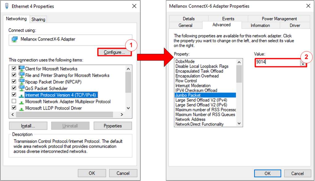
Figure 2‑2 Set frame size = Jumbo frame
1) On Local Area Connection Properties window, click “Configure” as shown in the left window of Figure 2‑2.
2) On Advanced Tab, select “Jumbo Packet”. Set Value to “9014 Bytes” for Jumbo Frame support, as shown in the right window of Figure 2‑2.
Note: If setting “Disabled”, Jumbo frame is not supported and the performance may be reduced.
2.3 Disabling Flow Control and Interrupt Moderation

Figure 2‑3 Disable Flow Control and Interrupt Moderation
1) Select “Flow Control” and set value to “Disabled”, as shown in the left window of Figure 2‑3.
2) Select “Interrupt Moderation” and set value to “Disabled”, as shown in the right window of Figure 2‑3.
2.4 Setting Number of RSS Queues and RSS Base Processor Number
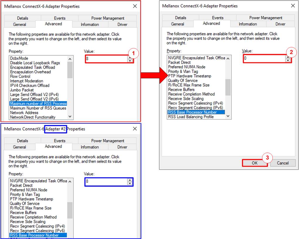
Figure 2‑4 Set Number of RSS Queues and RSS Base Processor Number
1) Configure the Maximum Number of RSS Queues to a value greater than 4; for instance, set it to 8 queues.
2) When the Ethernet card features multiple ports, ensure that the RSS Base Processor Number assigned to each port does not overlap. For instance, if there are two Ethernet ports and the Maximum Number of RSS Queues for both ports is set to 8, assign RSS Base Processor Number of 0 and 8 to each Ethernet port, respectively.
3) Save and exit all setting windows by clicking the “OK” button.
2.5 Checking Power Options Plan
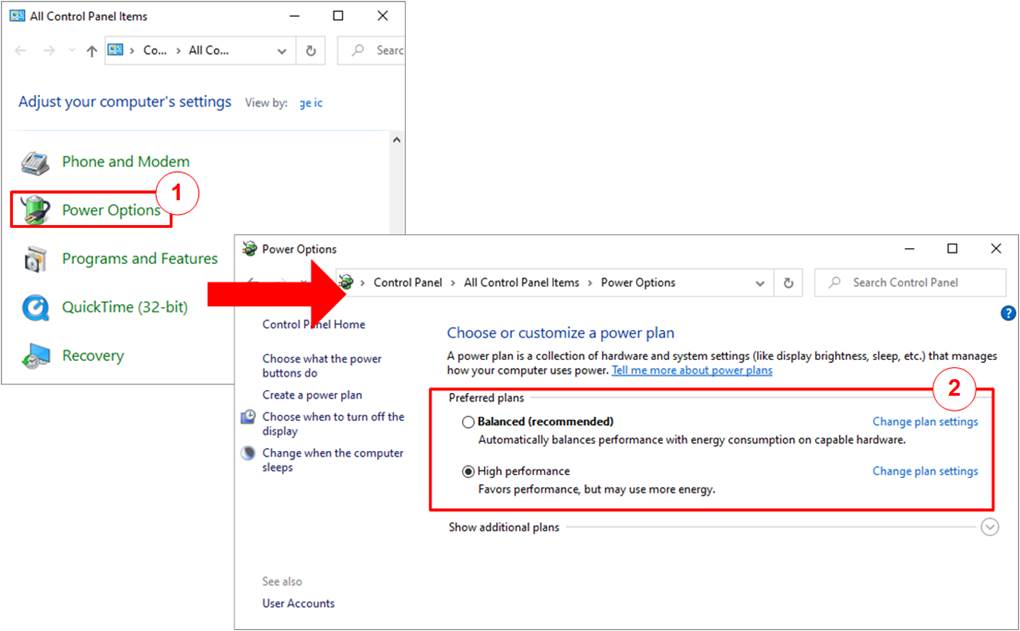
Figure 2‑5 Power options
1) Open Control Panel and select Power Options, as shown in the left window of Figure 2‑5.
2) Change setting to High Performance as shown in the right window of Figure 2‑5.
3 Test result when using FPGA and TestPC
3.1 Display TCPIP parameters
Choose option ‘0’ to display the current TCP/IP parameters. The console will show either eight parameters in Client/Server mode or nine parameters in Fixed MAC mode.
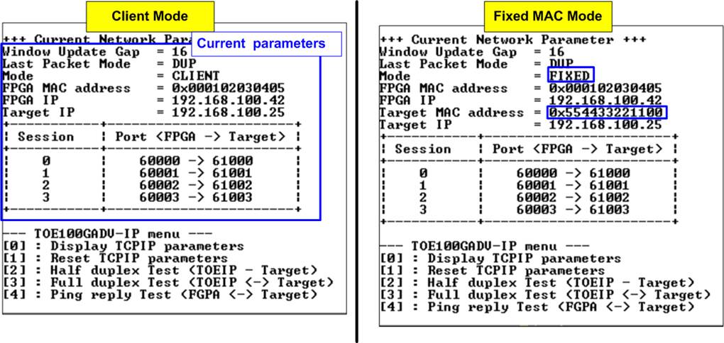
Figure 3‑1 Display current parameter result
Here are the details of the parameters
1) Window Update Gap: This sets the threshold value for transmitting a window update packet. The valid value range is 0x000 – 0x3FF (0-1023) and the threshold value unit is 1KB. The default value is 16.
2) Last Packet Mode: This flag enables the IP to send the duplicated last packet, packet with PSH flag, or normal packet when the IP transfers last data packet. The default value is DUP (duplicated packet).
3) Mode: This parameter sets the mode to TOE100GADV-IP to initialize in Server, Client, or Fixed MAC.
Note: When operating with a PC, it is recommended to initialize the IP in Client mode, especially when both the PC and FPGA are installed in the same network domain. However, if PC and FPGA are situated in different network domains, the Fixed-MAC mode must be selected. In this mode, the Target MAC address must configure to match the MAC address of the network switch within the FPGA domain.
4) FPGA MAC address: This parameter sets the 48-bit hex value to be the MAC address of the FPGA. The default value is 0x000102030405.
5) FPGA IP: This parameter sets the IP address of the FPGA. The default value is 192.168.100.42.
Note: This value serves as a Server IP address parameter for the test application on the PC.
6) Target MAC address (displayed when running Fixed MAC mode only): This parameter sets the 48-bit hex value to be the MAC address of the target device. The default value is 0x554433221100.
7) Target IP: This parameter sets the IP address of the target device (100G Ethernet on PC). The default value is 192.168.100.25.
8) Four FPGA port numbers: Left-hand side value of (FPGA -> Target). These parameters define the port numbers of the FPGA for all sessions. The default values for the four sessions are 60000, 60001, 60002, and 60003.
Note: This value serves as a Server port parameter for the test application on the PC.
9) Four Target port numbers: Right-hand side value of (FPGA -> Target). These parameters define the port number of the target device for transferring TCP payload data. The default values of the four sessions are 61000, 61001, 61002, and 61003.
To change any of these parameters, the user can set them using the menu option [1].
3.2 Reset TCPIP parameters
Choose option ‘1’ from the menu to reset the IP and modify IP parameters. This menu allows user to change IP settings or reset the TOE100GADV-IP. Upon selection of this option, the current parameters are displayed on the console. Press ‘x’ to keep the same parameters, or press any other key to modify them. Once the parameters are confirmed, the TOE100GADV-IP is reset and the initialization process begins.
This menu contains eight or nine parameters that must be set. Each parameter is validated before being loaded into the TOE100GADV-IP. If the input is invalid, the parameter remains unchanged. Once all parameters have been loaded, the IP is reset. The details of each parameter are described in topic 3.1 (Display TCPIP parameter) and their valid ranges are given below.
1) Mode: Input ‘0’ or ‘2’ to initialize the IP as Client mode or Fixed MAC mode, respectively.
Note: When the PC and FPGA are connected to different networks, which cannot communicate via the ARP process, the TOE100GADV-IP must be run in Fixed MAC mode to manually set the MAC address via the console.
2) Last Packet Mode: Input ‘0’ to set TOE100GADV-IP to send duplicated last packet, ‘1’ to set TOE100GADV-IP to send last packet with the PSH flag, or ‘2’ to set TOE100GADV-IP to send a normal last packet. The default value is ‘0’.
3) Window Update Gap: Set threshold value for transmitting a window update packet. The valid range is 0x000 – 0x3FF (0-1023), and the unit size of the threshold value is 1KB. The default value is 16.
4) FPGA MAC address: Input 12 digits of hex value, and add “0x” as a prefix to input it as a hex value.
5) FPGA IP address: Input four decimal digits separated by “.”, where the valid range for each digit is 0-255.
6) Target MAC address (displayed only when running Fixed MAC mode): Input 12 digits of hex value, and add “0x” as a prefix to input it as a hex value.
7) Target IP address: Input four decimal digits, similar to FPGA IP address. This value is IP address of PC.
8) FPGA port number: Input a value within the range of 0 to 65535.
9) Target port number: Input a value within the range of 0 to 65535.
Note: Each session must have a distinct port number.
After the parameters have been assigned, the final values are displayed on the console. Then, the reset signal is sent to the IP, and it initializes using the new parameters. Finally, “IP initialization complete” is displayed on the console once the initialization process is complete, as shown in Figure 3‑2.
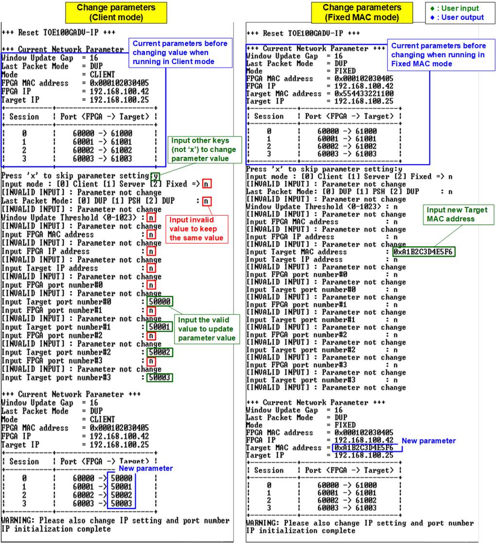
Figure 3‑2 Change IP parameter in Client and Fixed-MAC mode result
3.3 Half-duplex Test
Choose option ‘2’ from the menu to transfer data in a single direction for each session. The test application, ‘tcpdatatest.exe’, is called on the PC through the Command prompt, utilizing specified parameters for either receiving or sending data. The half-duplex test allows user to disable (option ‘0’), send data (option ‘1’), or receive data (option ‘2’) for each session individually. Furthermore, individual test parameters can be assigned to each session. The details regarding the operation when executing a Send test, Receive test, or Mixed test (Send and Receive) are elaborated below.
3.3.1 Send Test
When Test mode is configured to ‘1-Send test’ for transmitting data from the FPGA to the target (PC), the PC must execute ‘tcpdatatest’ application to receive data. The recommended parameters for that session must be utilized. The sequence for the Send test is outlined as follows.
1) On FPGA console, input test parameters of each session.
a) Test mode: ‘0’-Disable and skip to assign the next session, ‘1’-Send test.
b) Transfer size: The unit of transfer size is byte. The valid range is 0x1 – 0xFFFF_FFFF_FFFF. The input is a decimal unit when inputting only digit number. User adds “0x” as a prefix for hexadecimal unit.
c) Packet size: The unit of packet size is byte. The valid range value is 0x1 – 0xFFFF_FFFF_FFFF. The input is a decimal unit when inputting only digit number. User adds “0x” as a prefix for hexadecimal unit.
d) Bandwidth: Maximum transfer speed in percentage unit of 16,000 MB/s. The valid range is from 1-100.
Note: 16,000 MB/s is calculated by multiplying the user clock frequency (250 MHz) with the data width (512-bit).
e) Mode: This is the connection mode of the FPGA. Input ‘1’ to open connection using Server mode (Passive open) to operate with ‘tcpdatatest’, configured by Client mode.
Repeat the input assignment until all sessions have been configured.
2) Upon validation of all inputs, the recommended parameters for running the test application on the PC are displayed. Next, the parameters for the active session are displayed, and “Wait connection” is shown, indicating a wait for the application to be launched on the PC.
3) On the Command prompt at PC, input test parameters following the recommended values, except for the last two parameters, which can be adjusted for performance testing. The ‘tcpdatatest’ requires configuration of seven parameters.
>> tcpdatatest <mode> <dir> <server IP> <server port> <bytelen> <pattern><buffer>
a) Mode: Input ‘c’ to configure PC to operate as a client.
b) Dir: Input ‘r’ to set up PC for receiving and verifying test data from the FPGA.
c) Server IP: Input the same value as the IP address of the FPGA.
d) Server port: Input the same value as the port number of the FPGA on the selected session.
e) Bytelen: Input the same value as “Transfer size” from step 1b) on the selected session.
f) Pattern: Input ‘1’ to verify data from the FPGA or ‘0’ to skip data verification.
g) Buffer: Input a number between 1-5 (64KB – 1MB) as the buffer size for the application.
4) After running the test application, the port is created. Once the connections for all active sessions are completely established, three parameters of the target device are displayed on the console, i.e., the port number, Maximum Segment Size (MSS), and window scaling factor. Subsequently, the current amount of transferred data is displayed on the console for transmitted data and on the Command prompt for received data, updating every second. “Closed” might be displayed on the console after the completion of data transfer for a specific session.
Note: The displayed target port number corresponds to the actual port number managed by the OS. Thus, the real PC port number may not match the assigned parameter on the console.
5) After all connections are closed, the message “Half-duplex test complete” is displayed. Finally, the total amount of transferred data and the performance for all active sessions are displayed on the console for transmit performance and on the Command prompt for receive performance.
Figure 3‑3 illustrates an example of one-session Send test with data verification enabled in the test application. The left window is FPGA console operating as the Server, while the right window is Command prompt window on the PC operating as the Client. The performance result is equal to 4,955 MB/s.
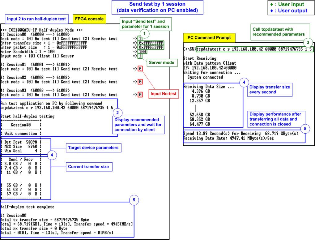
Figure 3‑3 One-session Send test with data verification
Figure 3‑4 shows an example of two-session Send test with data verification enabled in the test application. In comparison to the one-session test illustrated in Figure 3‑3, the performance of each session is reduced to be approximately 3800 MB/s. However, the overall performance is increased to 7,778 MB/s (3,985 + 3,739), reflecting a 57% improvement from the one-session test.
Note: When running multi-session test, the summation result from all active session does not present the absolute performance. This is because the multiple sessions of TOE100GADV-IP may not commence and conclude data transfer simultaneously. Some transfer period may only involve the transfer of data for one session.
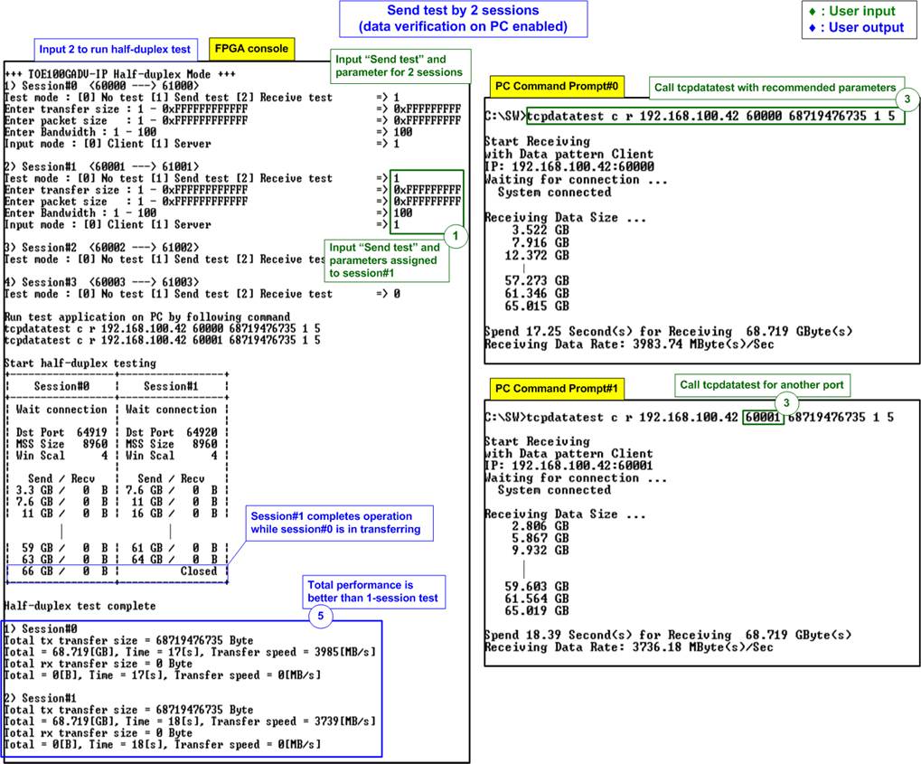
Figure 3‑4 Two-session Send test with data verification
Similarly, when increasing the number of sessions to four, the individual performance of each session is decreased while the overall performance is enhanced as shown in Figure 3‑5 and Figure 3‑6.
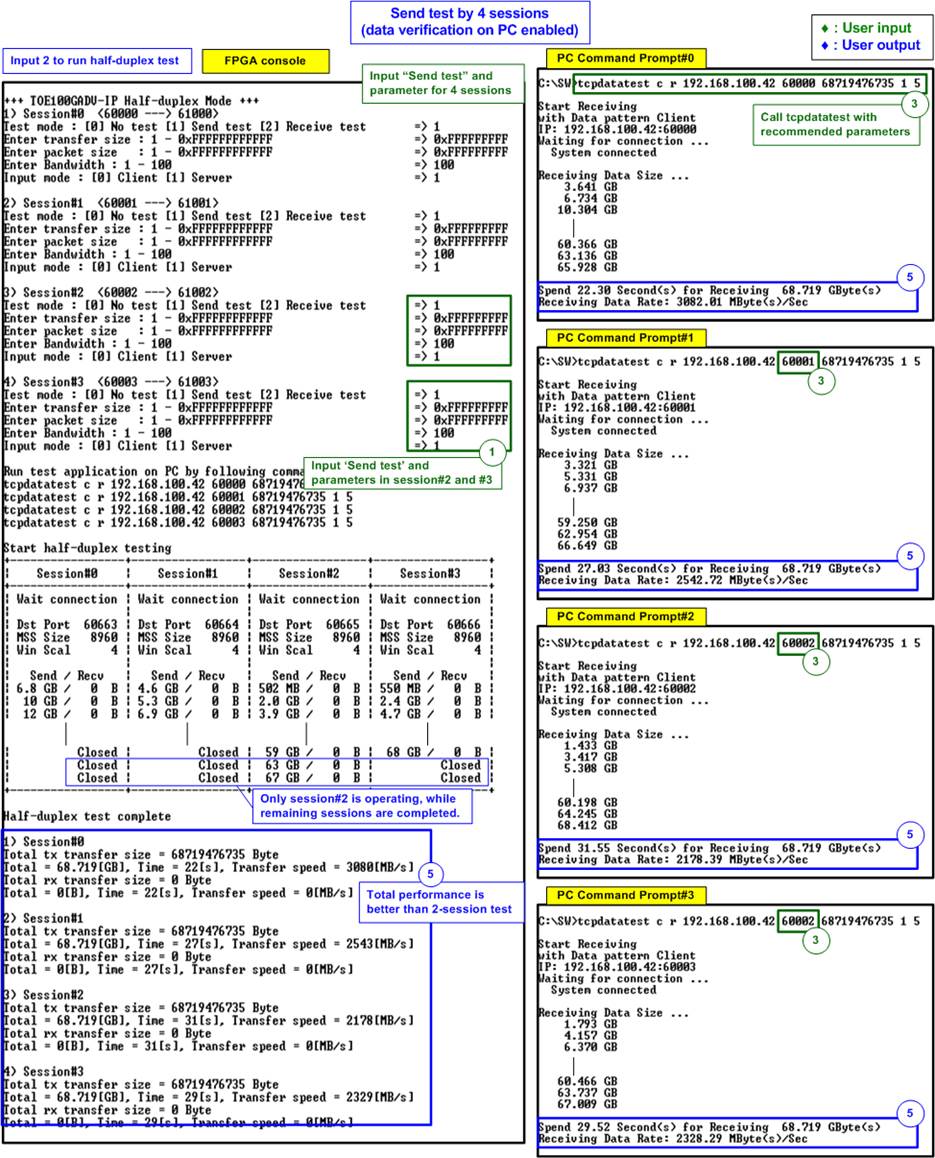
Figure 3‑5 Four-session Send test with data verification
The average total performance of four session is measured at 10,130 MB/s, indicating approximately 30% growth from two-session Send test. Therefore, users should consider the trade-off between resource utilization and the target performance when configuring the number of sessions for TOE100GADV-IP to align with the system requirements.

Figure 3‑6 Four-session Send test without data verification
Disabling the data verification feature on the PC to reduce CPU resource usage may lead to an increase in performance. As shown in Figure 3‑6, the total performance is slightly increased, moving from 10,130 MB/s to 10,986 MB/s.
Note: The performance by FPGA and PC may not be stable. It depends on how the OS manages the application during the test. The ability and efficiency of the application on the PC also play a crucial role in maximizing the potential of TOE100GADV-IP.
In specific applications, multiple sessions are employed to transfer various data types, each having a distinct data rate. This demo offers user the flexibility to define the maximum transfer speed for each TCP session individually, expressed in percentage units of 16,000 MB/s (derived from 250 MHz of user clock multiplied by a 512-bit data width). Consequently, users can assess the actual performance of each TCP session when transferring data between the PC and FPGA using multiple TCP sessions at varying data rate. Figure 3‑7 demonstrates the scenario of limiting the bandwidth of the other three sessions while session#0 operates at full bandwidth.
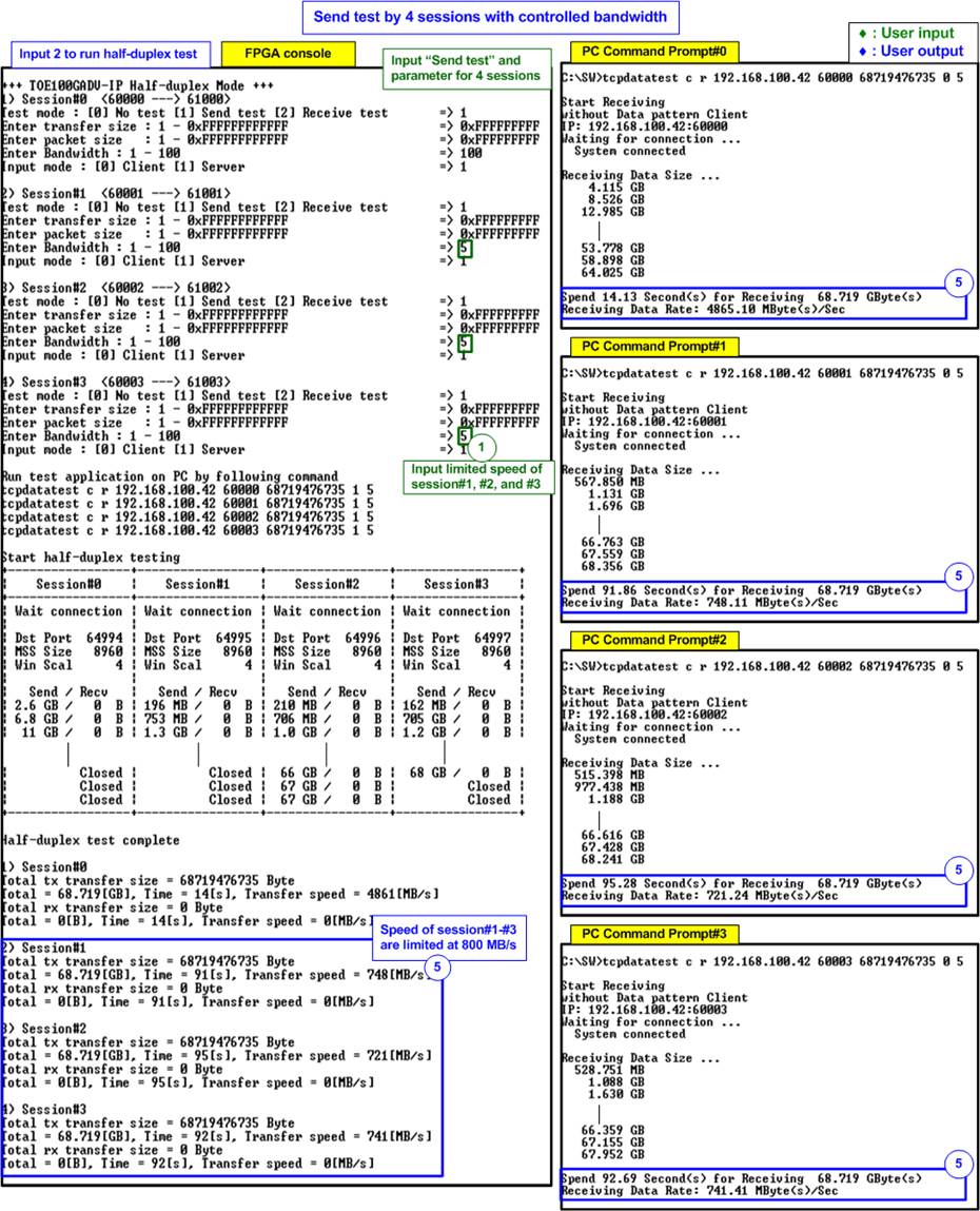
Figure 3‑7 Four-session Send test with limited transmit speed
When inputting test parameters on the console, if the input is invalid, the console will display “OUT-OF-RANGE INPUT” or “INVALID INPUT”. After that, the operation is cancelled, as shown in Figure 3‑8 and Figure 3‑9.
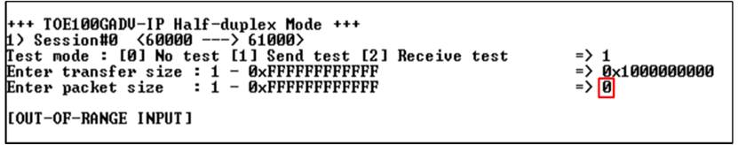
Figure 3‑8 Error from out-of-range input
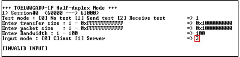
Figure 3‑9 Error from invalid input
3.3.2 Receive Test
When Test mode is configured to ‘2-Receive test’ for receiving data from the target (PC), the PC must execute ‘tcpdatatest’ application to send data. The recommended parameters for that session must be utilized. The sequence for the Receive test is outlined as follows.
1) On FPGA console, input test parameters of each session.
a) Test mode: ‘0’-Disable and skip to assign the next session, ‘2’-Receive test.
b) Transfer size: The unit of transfer size is byte. The valid range is 0x1 – 0xFFFF_FFFF_FFFF. The input is a decimal unit when inputting only digit number. User adds “0x” as a prefix for hexadecimal unit.
c) Data verification mode: ‘0’-disable data verification, ‘1’-enable data verification.
d) Bandwidth: Maximum transfer speed in percentage unit of 16,000 MB/s. The valid range is from 1-100. More description is previously stated in section 3.3.1 Send Test.
e) Mode: This is the connection mode of the FPGA. Input ‘1’ to open connection using Server mode (Passive open) to operate with ‘tcpdatatest’, configured by Client mode.
Repeat the input assignment until all sessions have been configured.
2) Upon validation of all inputs, the recommended parameters for running the test application on the PC are displayed. Next, the parameters for the active session are displayed, and “Wait connection” is shown, indicating a wait for the application to be launched on the PC.
3) On the Command prompt at PC, input test parameters following the recommended values, except for the last two parameters, which can be adjusted for performance testing. The ‘tcpdatatest’ requires configuration of seven parameters.
>> tcpdatatest <mode> <dir> <server IP> <server port> <bytelen> <pattern><buffer>
a) Mode: Input ‘c’ to configure PC to operate as a client.
b) Dir: Input ‘t’ to set up PC for sending test data to the FPGA.
c) Server IP: Input the same value as the IP address of the FPGA.
d) Server port: Input the same value as the port number of the FPGA on the selected session.
e) Bytelen: Input the same value as “Transfer size” from step 1b) on the selected session.
f) Pattern: Input the same value as “Data verification mode” from step 1c) on the selected session. ‘0’-Send dummy data, ‘1’-Send incremental data.
g) Buffer: Input a number between 1-5 (64KB – 1MB) as the buffer size for the application.
4) After running the test application, the port is created. Once the connections for all active sessions are completely established, three parameters of the target device are displayed on the console, i.e., the port number, Maximum Segment Size (MSS), and window scaling factor. Subsequently, the current amount of transferred data is displayed on the console for received data and on the Command prompt for transmitted data, updating every second. “Closed” might be displayed on the console after the completion of data transfer for a specific session.
Note: The displayed target port number corresponds to the actual port number managed by the OS. Thus, the real PC port number may not match the assigned parameter on the console.
5) After all connections are closed, the message “Half-duplex test complete” is displayed. Finally, the total amount of transferred data and the performance for all active sessions are displayed on the console (receive performance) and Command prompt (transmit performance).
Figure 3‑10 illustrates an example of one-session Receive test, where the data verification mode on the FPGA is enabled, and incremental data is sent by the PC. The left window showcases the FPGA console operating as the Server, while the right window displays the Command prompt window on the PC operating as the Client. The performance result is equal to 7,909 MB/s.
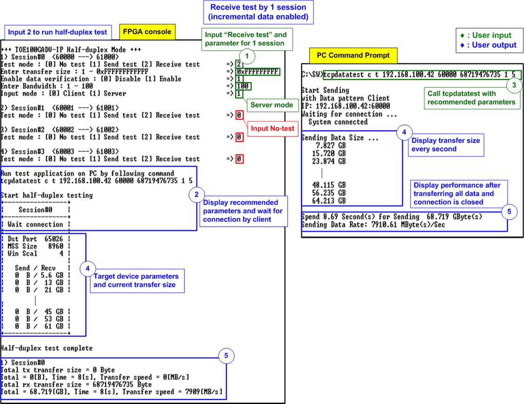
Figure 3‑10 One-session Receive test with incremental test data
Similar to the results in the Send test, the overall performance of the Read test is enhanced by expanding the number of sessions and reducing CPU tasks. Figure 3‑11 provides an example of the performance in a four-session Receive test where data verification on the FPGA is disabled, and dummy data is sent by the PC for load reduction. The total performance achieved is 11,966 MB/s.
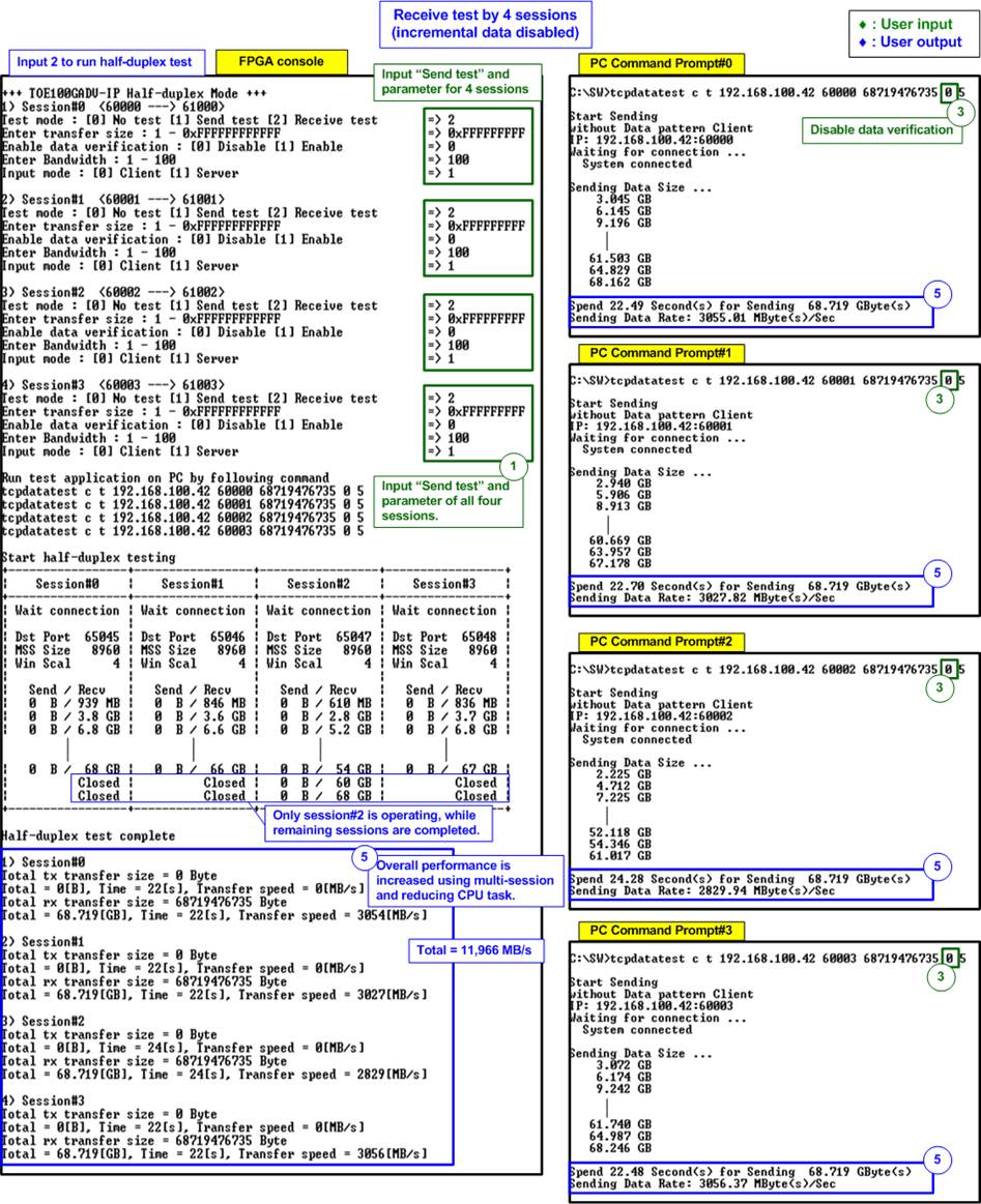
Figure 3‑11 Four-session Receive test with dummy data
In a multi-session Receive test, the performance per session is decreased, similar to the Send test result. However, the ability to configure the maximum speed per session allows users to assess the actual performance of each session under varying speed tests, as shown in Figure 3‑12.
Note: If users restrict the received speed of any sessions, the ‘Window Update Gap’ parameters do not equal zero to enable the transmission of Window update packets.
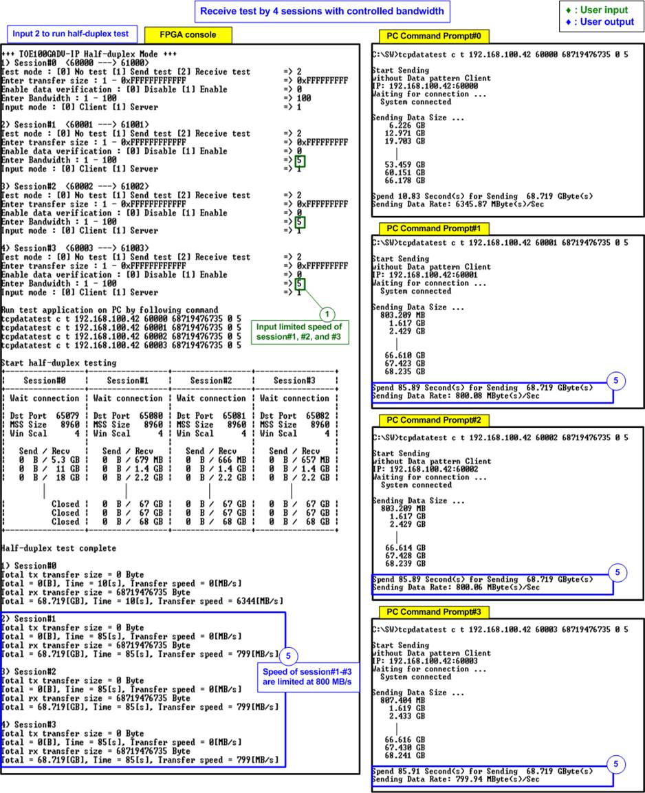
Figure 3‑12 Four-session Receive test with limited receive speed
3.3.3 Mixed Send - Receive Test
When user sets Test mode to ‘1-Send test’ for specific sessions and ‘2-Receive’ for the remaining sessions, the target (PC) must execute the ‘tcpdatatest’ applications to both receive and send data, aligning with the designated mode of each session on the FPGA. The sequence for running a Mixed Send - Receive test is described as follows.
1) On FPGA console, input test parameters of each session.
a) Test mode: ‘0’-Disable and skip to assign the next session, ‘1’-Send test, ‘2’-Receive test.
b) Transfer size: The unit of transfer size is byte. The valid range is 0x1 – 0xFFFF_FFFF_FFFF. The input is a decimal unit when inputting only digit number. User adds “0x” as a prefix for hexadecimal unit.
c) Packet size: The unit of packet size is byte. The valid range value is 0x1 – 0xFFFF_FFFF_FFFF. The input is a decimal unit when inputting only digit number. User adds “0x” as a prefix for hexadecimal unit.
d) Data verification mode: ‘0’-disable data verification, ‘1’-enable data verification.
e) Bandwidth: Maximum transfer speed in percentage unit of 16,000 MB/s. The valid range is from 1-100. More description is previously stated in section 3.3.1 Send Test.
f) Mode: This is the connection mode of the FPGA. Input ‘1’ to open connection using Server mode (Passive open) to operate with ‘tcpdatatest’, configured by Client mode.
Repeat the input assignment until all sessions have been configured.
2) Upon validation of all inputs, the recommended parameters for running the test application on the PC are displayed. Next, the parameters of the active session are displayed, and “Wait connection” is shown, indicating a wait for the application to be launched on the PC.
3) On the Command prompt, input test parameters following the recommended values, except for the last two parameters, which can be adjusted for performance testing. The ‘tcpdatatest’ requires configuration of seven parameters.
>> tcpdatatest <mode> <dir> <server IP> <server port> <bytelen> <pattern><buffer>
a) Mode: Input ‘c’ to configure PC to operate as a client.
b) Dir: Input ‘r’ to set up PC for receiving and verifying test data from the FPGA or
‘t’ to set up PC for sending test data to the FPGA.
c) Server IP: Input the same value as the IP address of the FPGA.
d) Server port: Input the same value as the port number of the FPGA on the selected session.
e) Bytelen: Input the same value as “Transfer size” from step 1b) on the selected session.
f) Pattern:
To receive data, input ‘1’ to verify data from the FPGA or ‘0’ to skip data verification.
To send data, input the same value as “Data verification mode” from step 1d) on the selected session. ‘0’-Send dummy data, ‘1’-Send incremental data.
g) Buffer: Input a number between 1-5 (64KB – 1MB) as the buffer size for the application.
4) After running the test application, the port is created. Once the connections for all active sessions are completely established, three parameters of the target device are displayed on the console, i.e., the port number, Maximum Segment Size (MSS), and window scaling factor. Subsequently, the current amount of transferred data for both transmit side and receive side is displayed on the console and Command prompt, updating every second. “Closed” might be displayed on the console after the completion of data transfer for a specific session.
Note: The displayed target port number corresponds to the actual port number managed by the OS. Thus, the real PC port number may not match the assigned parameter on the console.
5) After all connection are closed, the message “Half-duplex test complete” is displayed. Finally, the total amount of transferred data and the performance of all active sessions are displayed on the console and Command prompt.
Figure 3‑13 illustrates an example of executing a Send test for two sessions and a Receive test for two sessions.

Figure 3‑13 Two sessions run Send test and other two sessions run Receive test
3.4 Full duplex Test
Choose option ‘3’ from the FPGA console menu to perform a full-duplex test between the FPGA and PC. This test involves the simultaneous transfer of data in both directions. Once users configure parameters for all sessions, the FPGA console will display the recommended settings for running the ‘tcp_client_txrx_single’ application on the PC via the Command prompt. Execute ‘tcp_client_txrx_single’ for each TCP session, ensuring that the number of applications matches the active TCP sessions in the FPGA design. The sequence for running the test is outlined below.
1) On FPGA console, input test parameters of each session.
a) Test mode: ‘0’-Disable and skip to assign the next session, ‘1’-Full duplex test.
b) Transfer size: The unit of transfer size is byte. The valid range is 0x1 – 0xFFFF_FFFF_FFFF. The input is a decimal unit when inputting only digit number. User adds “0x” as a prefix for hexadecimal unit.
c) Packet size: The unit of packet size is byte. The valid range value is 0x1 – 0xFFFF_FFFF_FFFF. The input is a decimal unit when inputting only digit number. User adds “0x” as a prefix for hexadecimal unit.
d) Data verification mode: ‘0’-disable data verification, ‘1’-enable data verification.
e) Bandwidth: Maximum transfer speed in percentage unit of 16,000 MB/s. The valid range is from 1-100. More description is previously stated in section 3.3.1 Send Test.
f) Mode: Input ‘1’ to transfer as Server mode.
Repeat the input assignment until all sessions have been configured.
2) Upon validation of all inputs, the recommended parameters for running the test application on the PC are displayed. Next, the parameters for the active session are displayed, and “Wait connection” is shown, indicating a wait for the application to be launched on the PC.
3) On the Command prompt at PC, input test parameters following the recommended values, except for the last two parameters, which can be adjusted for performance testing. The ‘tcp_client_txrx_single’ requires configuration of five parameters.
>> tcp_client_txrx_single <server IP> <server port> <bytelen> <pattern><buffer>
a) Server IP: Input the same value as the IP address of the FPGA.
b) Server port: Input the same value as the port number of the FPGA on the selected session.
c) Bytelen: Input the same value as “Transfer size” from step 1b) on the selected session.
h) Pattern: Input the same value as “Data verification mode” from step 1d) on the selected session. ‘0’-Send dummy data, ‘1’-Send incremental data.
d) Buffer: Input a number between 1-5 (64KB – 1MB) as the buffer size for the application.
4) After running the test applications, the port is created. Once the connections for all active session are completely established, three parameters of the target device are displayed on the console, i.e., the port number, Maximum Segment Size (MSS), and window scaling factor. Subsequently, the current amount of transferred data in both directions is displayed on the console and Command prompt, updating every second. “Closed” might be displayed on the console after the completion of data transfer for a specific session
Note: The displayed target port number corresponds to the actual port number managed by the OS. Thus, the real PC port number may not match the assigned parameter on the console.
5) After all connection are closed, the message “Full-duplex test complete” is displayed. Finally, the total amount of transferred data and the performance for all active sessions are displayed on the console and Command prompt in both transfer directions.
Figure 3‑14 illustrates an example of a four-session full-duplex test, where the data verification mode on the FPGA is enabled. In this configuration, incremental data is sent by the PC, and the received data is verified by the PC as well. The left window showcases the FPGA console operating as the Server, while the right window displays four Command prompt windows on the PC operating as the Client.

Figure 3‑14 Full duplex test with data verification
3.5 Ping Test
Choose option ‘4’ from the FPGA console menu to run Ping reply test. Upon selecting this option, the console will display the message “Press any key to exit Ping test”, as illustrated in Figure 3‑15. After that, users can enter the command “ping <FPGA board IP address>” in the Command prompt to commence the Ping command test, as shown in Figure 3‑16.

Figure 3‑15 Ping reply mode result on FPGA console
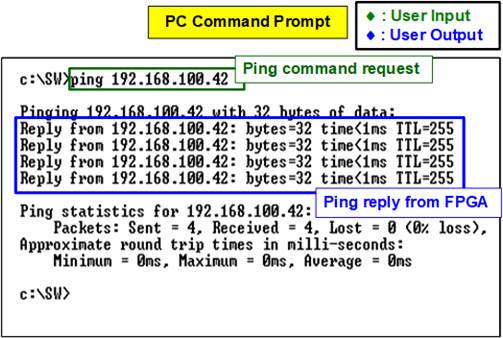
Figure 3‑16 Ping command result on PC
To exit this menu, users can press any key(s) on the console. Subsequently, the main menu will be displayed, as shown in Figure 3‑17.
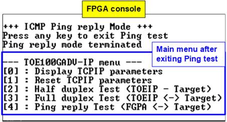
Figure 3‑17 Main menu is re-displayed after exiting the Ping test
4 Test result when using two FPGAs
4.1 Display TCPIP parameters
Choose option ‘0’ to display the current TCP/IP parameters. The console will show either eight parameters in Client/Server mode or nine parameters in Fixed MAC mode.
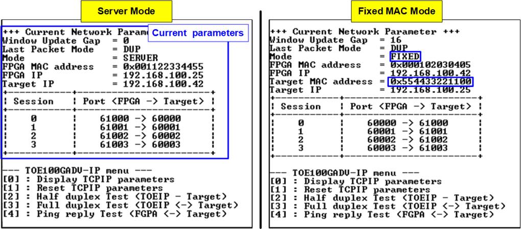
Figure 4‑1 Display current parameter result
Here are the details of the parameters
1) Window Update Gap: This sets the threshold value for transmitting a window update packet. The valid value range is 0x000 – 0x3FF (0-1023). and the threshold value unit is 1KB. The default value is 16.
2) Last Packet Mode: This flag enables the IP to send the duplicated last packet, packet with PSH flag, or normal packet when the IP transfers last data packet. The default value is DUP (duplicated packet).
3) Mode: This parameter sets the mode to TOE100GADV-IP to initialize in Server, Client, or Fixed MAC.
Note: When two FPGAs are installed in different network domains, the Fixed-MAC mode must be selected. In this mode, the Target MAC address must configure to match the MAC address of the network switch within each FPGA domain.
4) FPGA MAC address: This parameter sets the 48-bit hex value to be the MAC address of the FPGA. The default value is 0x000102030405 (Client/Fixed MAC mode) or 0x001122334455 (Server mode).
5) FPGA IP: This parameter sets the IP address of the FPGA. The default value is 192.168.100.42 (Client/Fixed MAC mode) or 192.168.100 .25 (Server mode).
6) Target MAC address (displayed when running Fixed MAC mode only): This parameter sets the 48-bit hex value to be the MAC address of the target device. The default value is 0x554433221100.
7) Target IP: This parameter sets the IP address of the target device (another FPGA). The default value is 192.168.100.25 (Client/Fixed MAC mode) or 192.168.100.42 (Server mode).
8) Four FPGA port numbers: These parameters set the port number of this FPGA for all session. The default value is 60000 - 60003 (Client/Fix MAC mdoe) or 61000 – 61003 (Server mode).
9) Four Target port number: These parameters set the port number of the target device (another FPGA) to transfer TCP payload data. The default value is 61000 - 61003 (Client/Fix MAC mode) or 60000 - 60003 (Server mode).
To change any of these parameters, the user can set them using the menu option [1].
4.2 Reset TCPIP parameters
Choose option ‘1’ from the menu to reset the IP and modify IP parameters. This menu allows user to change IP settings or reset the TOE100GADV-IP. Upon selection of this option, the current parameters are displayed on the console. Press ‘x’ to keep the same parameters, or press any other key to modify them. Once the parameters are confirmed, the TOE100GADV-IP is reset and the initialization process begins.
This menu contains eight or nine parameter that must be set. Each parameter is validated before being loaded into the TOE100GADV-IP. If the input is invalid, the parameter remains unchanged. Once all parameters have been loaded, the IP is reset. The details of each parameter are described in topic 4.1 (Display TCPIP parameter) and their valid ranges are given below.
Note:
· Please ensure that one of the following initialization modes is set on both FPGAs:
Server – Client (only used for the same network domain), Client – Fixed MAC, or Fixed MAC – Fixed MAC.
· When operating in Server – Client mode, if the parameters on the Server need to be reset, the Client FPGA must also be reset. Additionally, the Server must be reset firstly before the Client to ensure that it waits until the ARP request is sent by the Client.
· It is essential to match the parameters of both FPGAs as listed below.
a. The Target IP address of board#1 = The FPGA IP address of board #2
b. The FPGA IP address of board#1 = The Target IP address of board #2
c. All Target port numbers of board#1 = All FPGA port numbers of board#2
d. All FPGA port numbers of board#1 = All Target port numbers of board#2
1) Mode: Input ‘0’ (Client), ‘1’ (Server), or ‘2’ (Fixed MAC) to determine FPGA initialization mode.
2) Last Packet Mode: Input ‘0’ to set TOE100GADV-IP to send duplicated last packet, ‘1’ to set TOE100GADV-IP to send last packet with the PSH flag, or ‘2’ to set TOE100GADV-IP to send a normal last packet. The default value is ‘0’.
3) Window Update Gap: Set threshold value for transmitting a window update packet. The valid range is 0x000 – 0x3FF (0-1023), and the unit size of the threshold value is 1KB. The default value is 16.
4) FPGA MAC address: Input 12 digits of hex value, and add “0x” as a prefix to input it as a hex value.
5) FPGA IP address: Input four decimal digits separated by “.”, where the valid range for each decimal digit is 0-255.
6) Target MAC address (displayed only when running Fixed MAC mode): Input 12 digits of hex value, and add “0x” as a prefix to input it as a hex value.
7) Target IP address: Similar to FPGA IP address, this value is a set of four decimal digits.
8) FPGA port number: Input a value within the range of 0 to 65535.
9) Target port number: Input a value within the range of 0 to 65535.
After the parameters have been assigned, the final values are displayed on the console. Next, the reset signal is sent to all IPs, and it initializes using the new parameters. Finally, “IP initialization complete” is displayed on the console once the initialization process is complete, as shown in Figure 4‑2 and Figure 4‑3.
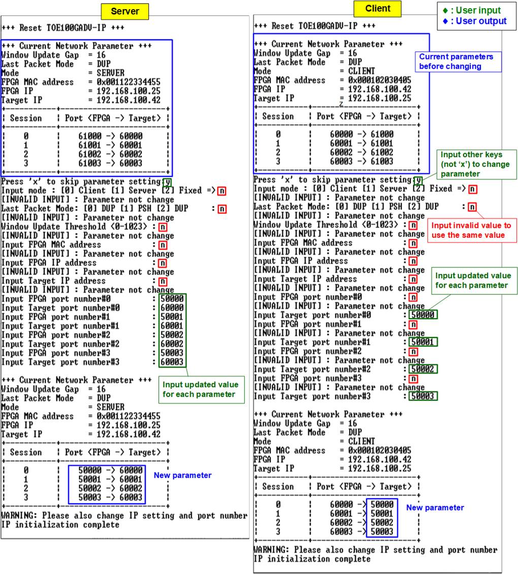
Figure 4‑2 Change IP parameter in Server and Client mode result
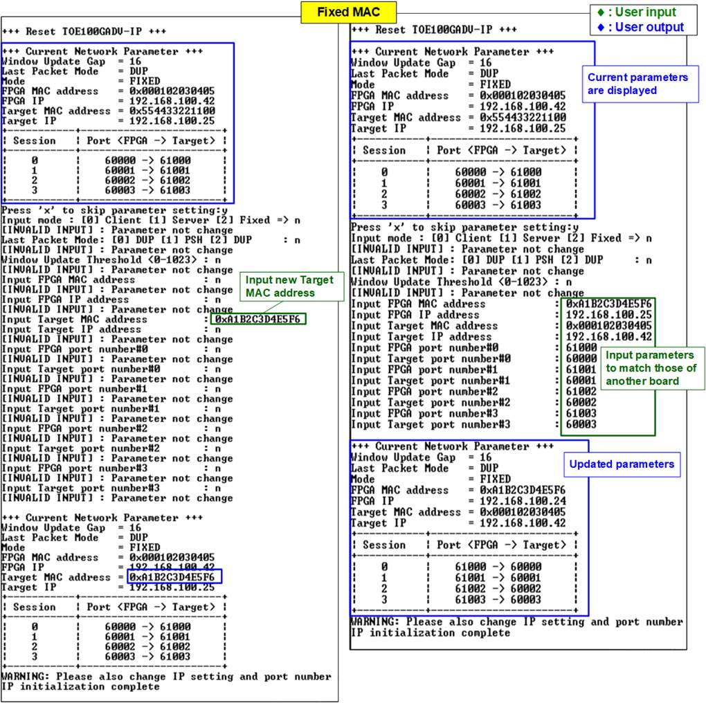
Figure 4‑3 Change IP parameter in Fixed MAC mode result
4.3 Half-duplex Test
To perform data transfer in a single direction between two FPGAs, choose option ‘2’ to initiate a half-duplex test on FPGA@board1 and FPGA@board2, running the Send test and Receive test, respectively. The half-duplex test allows users to configure test parameters on the console for each session independently. The sequence for running the test when the Server runs the Send test and the Client runs the Receive test is outlined below.
Note: The mode set in the half-duplex test to establish the connection is assigned. The end-point designated as the Client creates the connection, while the end-point designated as the Server waits for the connection. However, the close connection mode is determined by the test mode, either Send or Receive. The end-point responsible for sending data is the one that closes the connection as the Client. This is not related to the initialization mode, which is set to be Client, Server, or Fixed-MAC mode. Both FPGAs must set in different modes, where one is designated as the Client and the other as the Server, to open the port using different modes.
1) On FPGA@board1 console which is running Receive test, input test parameters under half-duplex test menu.
a) Test mode: ‘0’-Disable and skip to assign the next session, ‘2’-Receive test.
b) Transfer size: The unit of transfer size is byte. The valid range is 0x1 – 0xFFFF_FFFF_FFFF. The input is a decimal unit when inputting only digit number. User adds “0x” as a prefix for hexadecimal unit.
c) Data verification mode: ‘0’-disable data verification, ‘1’-enable data verification.
d) Bandwidth: Maximum transfer speed in percentage unit of 16,000 MB/s. The valid range is from 1-100. More description is previously stated in section 3.3.1 Send Test.
e) Mode: Input ‘1’ to open connection using Server mode (Passive open).
Repeat the input assignment until all sessions have been configured.
2) If all inputs on the FPGA@board1 console are valid, the console will present the parameters of the active sessions and display the message “Wait connection”, indicating a wait for the Client (FPGA@board2) to establish a connection.
3) On FPGA@board2 console which is running Send test, input test parameters under half-duplex test menu.
a) Test mode: ‘0’-Disable and skip to assign the next session, ‘1’-Send test.
b) Transfer size: The unit of transfer size is byte. The valid range is 0x1 – 0xFFFF_FFFF_FFFF. The input value must match “Transfer size” from step 1b) on the selected session.
c) Packet size: The unit of packet size is byte. The valid range value is 0x1 – 0xFFFF_FFFF_FFFF. The input is a decimal unit when inputting only digit number. User adds “0x” as a prefix for hexadecimal unit.
d) Bandwidth: Maximum transfer speed in percentage unit of 16,000 MB/s. The valid range is from 1-100. More description is previously stated in section 3.3.1 Send Test.
e) Mode: Input ‘0’ to open connection using Client mode (Active open).
Repeat the input assignment until all sessions have been configured.
4) If all inputs on the FPGA@board2 console are valid, the console will present the parameters of the active sessions and display the message “Press any key to proceed”, indicating that it is waiting for users to enter any key on the FPGA@board2 console. Upon user input, the ports are created.
5) Once the connections for all active sessions are completely established, three parameters of the target device are displayed on the console, i.e., the port number, Maximum Segment Size (MSS), and window scaling factor. Subsequently, the current amount of transferred data is displayed on both consoles, updating every second. In this scenario, the FPGA@board1 console shows the transmitted data, while the FPGA@board2 console shows the received data. “Closed” might be displayed on the console after the completion of data transfer for a specific session.
6) After all connection are closed, the message “Half-duplex test complete” is displayed on both consoles. Finally, the total amount of transferred data and the performance for all active sessions are displayed on both consoles.
Figure 4‑4 illustrates an example of a one-session half-duplex test between two FPGAs (FPGA-to-FPGA). The left window represents the Receive test console (Server or FPGA@board#1), and the right window displays the Send test console (Client or FPGA@board#2). In the FPGA-to-FPGA test environment, a high performance of 12,380 MB/s is achieved, nearly reaching the maximum line rate of 100G Ethernet connection (12,500 MB/s).
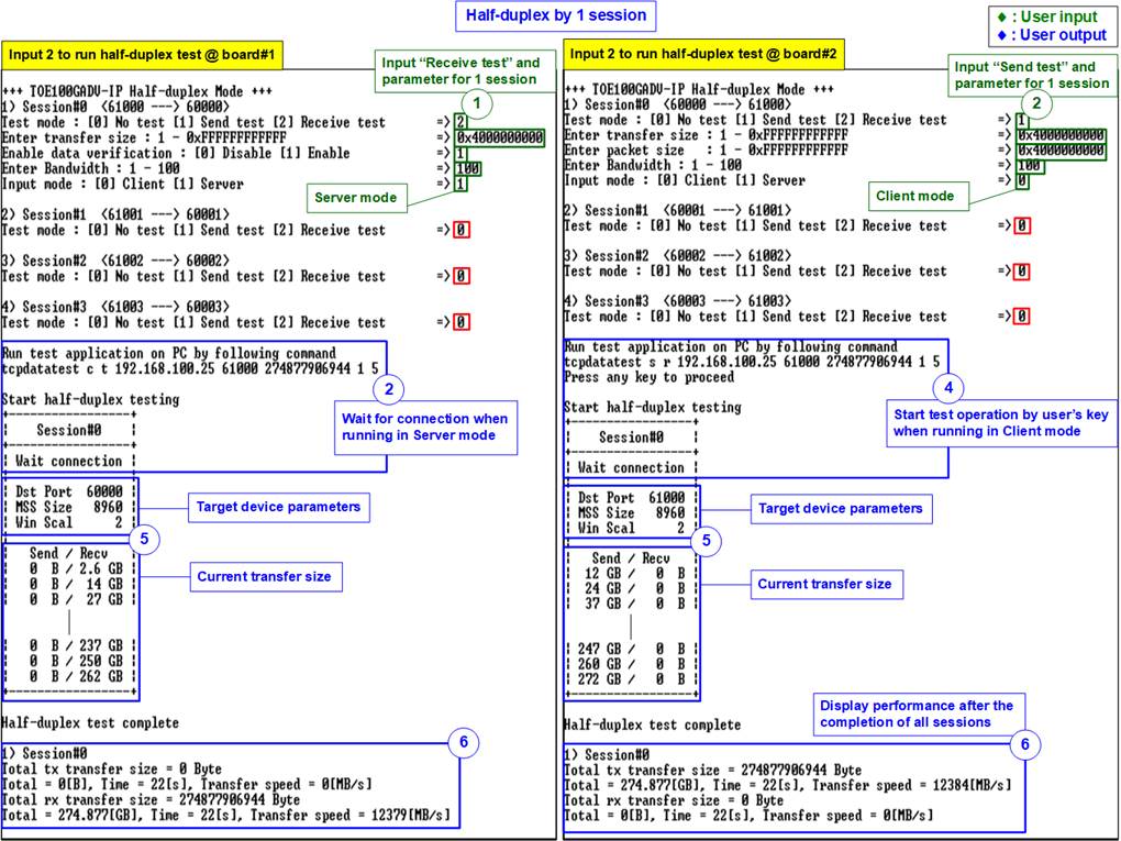
Figure 4‑4 One-session half-duplex test (FPGA-to-FPGA)
Figure 4‑5 presents an example of a four-session half-duplex test between FPGAs (FPGA-to-FPGA). Each session achieves an equal data transfer rate of 3,092 MB/s, resulting in an overall performance of about 12,368 MB/s. A comparison with Figure 4‑4 indicates that there is no difference in performance between running a one-session and a four-session test. Furthermore, the results highlight that the performance of FPGA-to-FPGA testing surpasses that of FPGA-to-PC testing.
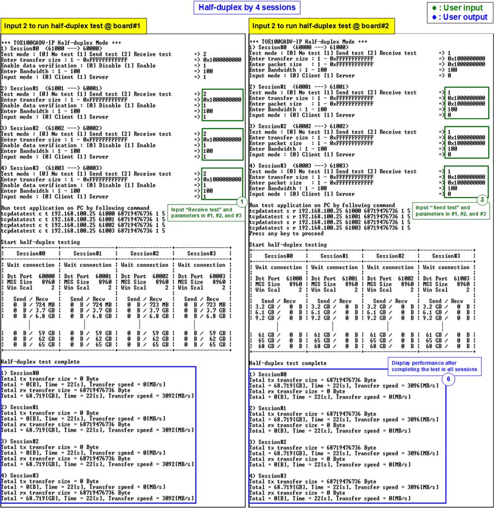
Figure 4‑5 Four-session half-duplex test (FPGA-to-FPGA)
Figure 4‑6 and Figure 4‑7 illustrate the results of half-duplex test when limiting a maximum speed on Sender test and Receiver test, respectively.
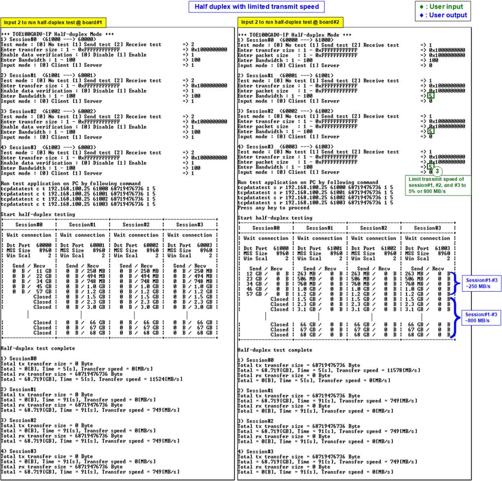
Figure 4‑6 Four-session half-duplex test (FPGA-to-FPGA) with limited send speed
The results in Figure 4‑6 demonstrate high performance transfer on session#0 when compared to the other sessions (session#1-#3). Throughout the data transfer period, the performance of session#1-#3 falls below the specified value (5% of 16,000MB/s = 800 MB/s) due to shared bandwidth with Session#0. As the result, TOE100GADV-IP on FPGA board#1 mainly receives data from the user logic of session#0.
Once the data transfer in session#0 is completed, session#1-#3 can achieve the specified speed of 800 MB/s.
On the contrary, half-duplex performance becomes more predictable when the maximum received speed is constrained. Referring to the four-session test without speed limit in Figure 4‑5, the overall received performance at 100% is 12,368 MB/s. When the maximum received speed of three sessions is restricted to 5%, the performance for the last session without any limits (100%) is 12,368 – (800x3) = 9,968 MB/s. As shown in Figure 4‑7, sessions#1-#3, limited to a maximum speed of 5%, achieve 800 MB/s from the beginning of the test. Finally, the average result for session#0 reaches approximately 9,900 MB/s, aligning with earlier calculation.
Note: If the received speed is limited, the transmission of window update packets must be enabled by setting the ‘Window Update Gap’ value to a non-zero value.

Figure 4‑7 Four-session half-duplex test (FPGA-to-FPGA) with limited receive speed
4.4 Full duplex Test
Choose option ‘3’ from the FPGA console menu to perform a full-duplex test on FPGA@board1 and FPGA@board2. The full-duplex test allows user to configure test parameters on the console for each session independently. The sequence for running the test is outlined below.
Note: The mode set in the full-duplex test to establish and terminate connection is assigned. The Client is responsible for creating and terminating the connection, while the Server awaits the opening and termination of the connection. This is not related to the initialization mode, which is set to be Client, Server, or Fixed-MAC mode. Both FPGAs must set in different modes, where one is designated as the Client and the other as the Server, to open the port using different modes.
1) On FPGA@board1 console which is running as Server, input test parameters under full-duplex test menu.
a) Test mode: ‘0’-Disable and skip to assign the next session, ‘1’-Full-duplex test.
b) Transfer size: The unit of transfer size is byte. The valid range is 0x1 – 0xFFFF_FFFF_FFFF. The input is a decimal unit when inputting only digit number. User adds “0x” as a prefix for hexadecimal unit.
c) Packet size: The unit of packet size is byte. The valid range value is 0x1 – 0xFFFF_FFFF_FFFF. The input is a decimal unit when inputting only digit number. User adds “0x” as a prefix for hexadecimal unit.
d) Data verification mode: Input ‘1’ to enable data verification sent from FPGA@board2.
e) Bandwidth: Maximum transfer speed in percentage unit of 16,000 MB/s. The valid range is from 1-100. More description is previously stated in section 3.3.1 Send Test.
f) Mode: Input ‘1’ to open and close connection using Server mode (Passive open/close).
Repeat the input assignment until all sessions have been configured.
2) If all inputs on the FPGA@board1 console are valid, the console will present the parameters of the active sessions and display the message “Wait connection”, indicating a wait for the Client (FPGA@board2) to establish a connection.
3) On FPGA@board2 console which is running as Client, input test parameters under full-duplex test menu.
a) Test mode: ‘0’-Disable and skip to assign the next session, ‘1’-Full-duplex test.
b) Transfer size: The unit of transfer size is byte. The valid range is 0x1 – 0xFFFF_FFFF_FFFF. This input value must match “Transfer size” from step 1b) on the selected session.
c) Packet size: The unit of packet size is byte. The valid range value is 0x1 – 0xFFFF_FFFF_FFFF. The input is a decimal unit when inputting only digit number. User adds “0x” as a prefix for hexadecimal unit.
d) Data verification mode: Input ‘1’ to enable data verification sent from FPGA@board1.
e) Bandwidth: Maximum transfer speed in percentage unit of 16,000 MB/s. The valid range is from 1-100. More description is previously stated in section 3.3.1 Send Test.
f) Mode: Input ‘0’ to open and close connection using Client mode (Active open/close).
Repeat the input assignment until all sessions have been configured.
4) If all inputs on the FPGA@board2 console are valid, the console will present the parameters of the active sessions and display the message “Press any key to proceed”, indicating that it is waiting for users to enter any key on FPGA@board2 console. Upon user input, the ports are created.
5) Once the connections for all active sessions are completely established, three parameters of the target device are displayed on the console, i.e., port number, Maximum Segment Size (MSS), and window scaling factor. Subsequently, the current amount of transferred data is displayed on both consoles, updating every second. Both consoles show the amount of transferred data in both directions. “Closed” might be displayed on the console after the completion of data transfer for a specific session.
6) After all connection are closed, the message “Full-duplex test complete” is displayed on both consoles. Finally, the total amount of transferred data and the performance for all active sessions are displayed on both consoles.
Figure 4‑8 and Figure 4‑9 show the results of two-session and four-session full duplex tests between two FPGAs (FPGA-to-FPGA), respectively. The left window represents the test console of Server or FPGA@board#1, and the right window displays the test console of Client or FPGA@board#2. As observed in the results of the half-duplex test, the FPGA-to-FPGA test environment consistently achieves high performance, regardless of the number of active sessions ranging from 1 to 4. The overall performance remains stable at approximately 12,000 MB/s.
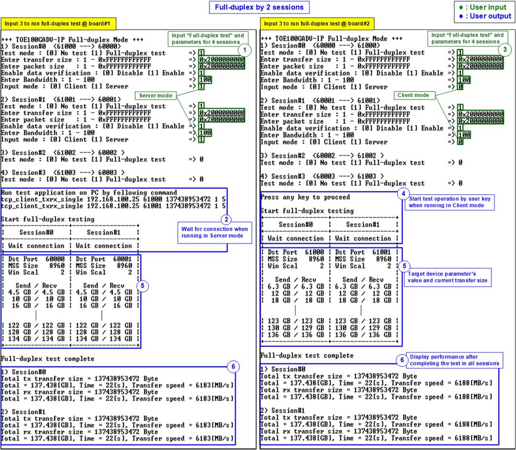
Figure 4‑8 Two-session full duplex test (FPGA-to-FPGA)
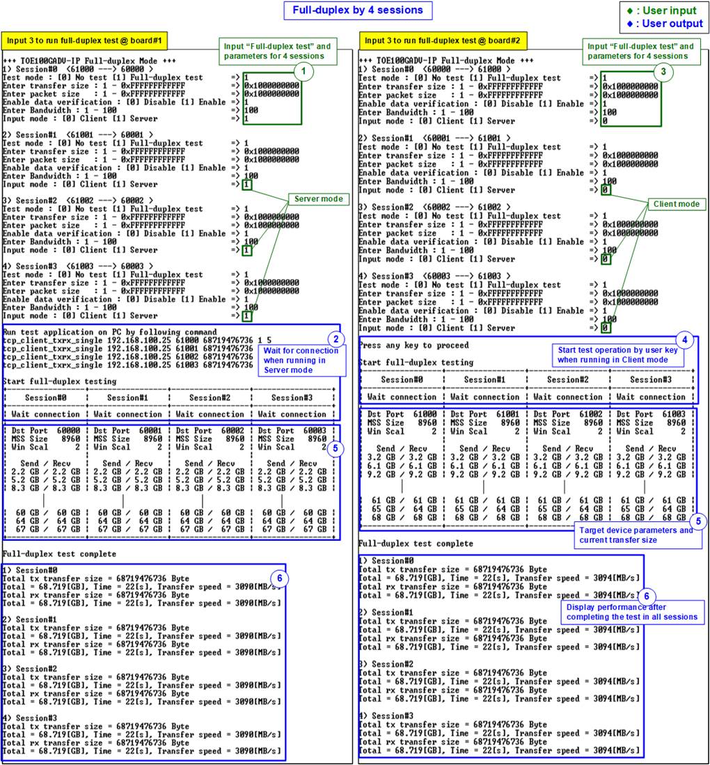
Figure 4‑9 Four-session full duplex test (FPGA-to-FPGA)
5 Revision History
|
Revision |
Date |
Description |
|
1.00 |
12-Feb-24 |
Initial version release |