TOE10G-IP reference design manual
2.1 10G Ethernet PCS/PMA (10GBASE-R)
3.1 ‘recv_tcp_client_10G’ for Send Data Test
3.2 ‘send_tcp_client_10G’ for Receive Data Test
1 Introduction
The TCP/IP is the Internet Protocol Suite for networking applications, consisting of four layers: Application, Transport, Internet, and Network Access. Figure 1‑1 shows how the Network Access layer is split into two sublayers, Link and Physical, to connect them with the hardware implementation using an FPGA.
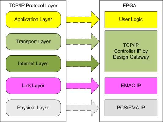
Figure 1‑1 TCP/IP Protocol Layer
The TOE10G-IP implements the Transport and Internet layers of the TCP/IP Protocol using full hardwire logic, without the need for a CPU or DDR. This allows the user logic to be designed for processing the TCP payload data at the user interface of TOE10G-IP. The TOE10G-IP is responsible for building an Ethernet packet that contains the TCP payload data from the user and transmitting it to the Ethernet MAC (EMAC). If the user data size exceeds the maximum Ethernet packet size, the TOE10G-IP will split the data into multiple packets for transmission. To construct a complete Ethernet packet, the TOE10G-IP must process and append the TCP/IP header to the packet before transmitting it. On the other hand, when the TOE10G-IP receives an Ethernet packet from EMAC, it extracts and verifies the packet header. If the packet is valid, the TOE10G-IP extracts the TCP payload data and forwards it to the user logic. Otherwise, the packet is rejected.
The lower layer protocols are implemented by EMAC-IP and PCS/PMA-IP. PCS/PMA-IP is an IP core provided by AMD Xilinx without charge, while EMAC-IP can be implemented by 10G25GEMAC-IP from Design Gateway or the Ethernet MAC system from AMD Xilinx.
The reference design provides an evaluation system which includes simple user
logic to transfer TCP payload data as half-duplex transfer using TOE10G-IP. On
the PC, one of two test applications, ‘send_tcp_client_10G’ for sending data or
‘recv_tcp_client_10G’ for receiving data, must be executed.
Most test parameters of this reference design are configured by constant values, assigned by the user logic. The test status is indicated by LEDs on the FPGA board. More details of the demo are described below.
2 Hardware overview
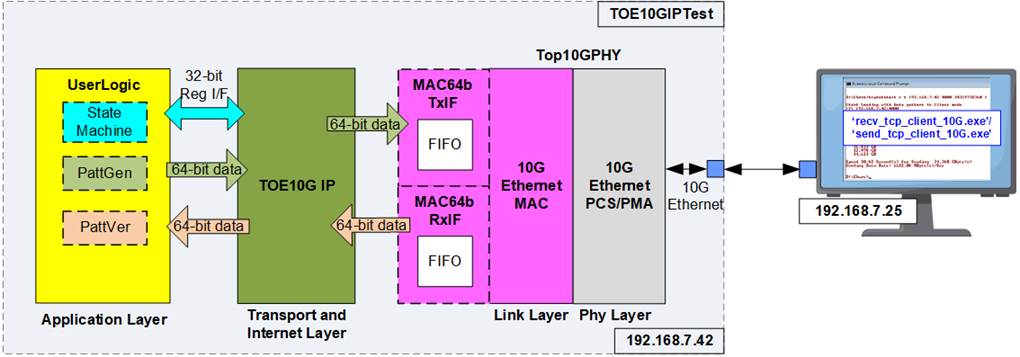
Figure 2‑1 Demo Block Diagram
In test environment, the FPGA transfers data using the TCP/IP protocol with the PC. Once the FPGA completely boots up, it initializes using Client mode by transferring ARP packets with the PC to retrieve the PC’s MAC address from its IP address. Two applications, ‘recv_tcp_client_10G’ and ‘send_tcp_client_10G’, are prepared on the PC for data transfer testing with the FPGA.
Within the FPGA system, the TOE10G-IP connects to the Ethernet system (Top10GPHY), comprising the Ethernet MAC and Ethernet PCS/PMA. In specific cases where the Ethernet MAC cannot transfer each packet data continuously, adapter logics must be connected between TOE10G-IP and the Ethernet system. The user interface of the TOE10G-IP connects to the UserLogic, which is divided into three submodules for three user interfaces: a state machine for controlling and monitoring parameters via a 32-bit Register interface, PattGen for generating test data via a 64-bit Tx FIFO interface, and PattVer for receiving and verifying test data via a 64-bit Rx FIFO interface.
The Ethernet system, TOE10G-IP, and UserLogic operate in a single clock domain at 156.25 MHz, sourced by the Ethernet system. More details of each module inside the TOE10GIPTest are described as follows.
2.1 10G Ethernet PCS/PMA (10GBASE-R)
The 10G Ethernet PCS/PMA (10GBASE-R) IP core implements the physical layer of 10G Ethernet. It provides a connection to the optical module for a 10GBASE-SR optical link. The user interface is 64-bit XGMII interface running at 156.25 MHz, designed to connect with a 10G Ethernet MAC. This IP core is provided by AMD Xilinx at no cost. For more details on the core, please refer to the following link.
https://www.xilinx.com/products/intellectual-property/10gbase-r.html
For UltraScale+ device support, refer to the 10G/25G Ethernet Subsystem.
2.2 10G Ethernet MAC
The 10G Ethernet MAC implements the data link layer of 10G Ethernet. It connects to the 10G Ethernet PCS/PMA via a 64-bit XGMII interface running at 156.25 MHz. The user interface for connecting with TOE10G-IP uses a 64-bit AXI4-ST standard. There are multiple solutions for 10G Ethernet MAC using the 64-bit AXI4-ST standard. This section illustrates two Ethernet MAC IPs: 10G25GEMAC-IP from Design Gateway and 10G Ethernet MAC-IP from AMD Xilinx.
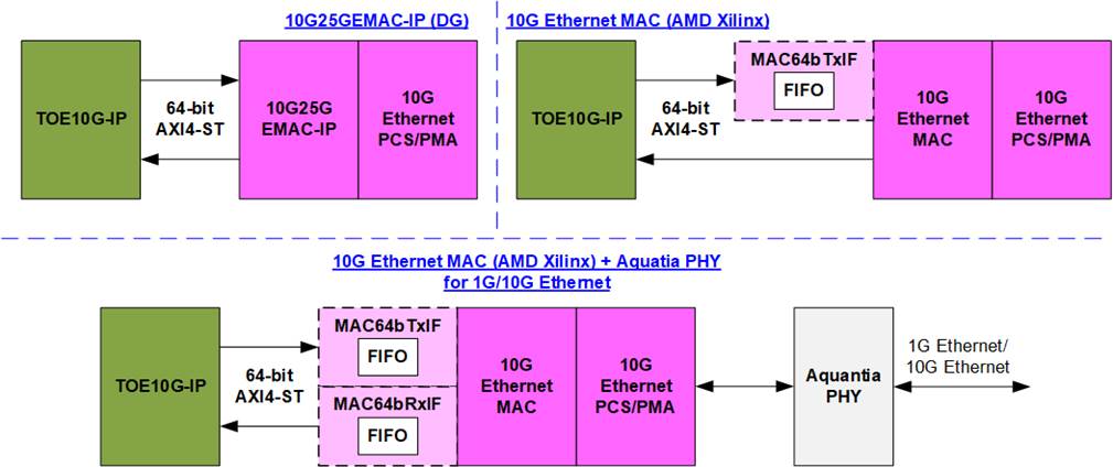
Figure 2‑2 10G Ethernet MAC connection with TOE10G-IP
The TOE10G-IP requires continuous data transmission for each packet transfer on the AXI4-ST interface, which matches the characteristics of 10G25GEMAC-IP from Design Gateway when running at 10G Ethernet speed. Therefore, the TOE10G-IP can directly connect to 10G25GEMAC-IP. However, the Tx interface of the 10G Ethernet MAC from AMD Xilinx may pause data transmission by de-asserting the ready signal during a packet transfer, necessitating the use of the Tx adapter, MAC64bTxIF, to connect between the TOE10G-IP and the 10G Ethernet MAC, as shown in Figure 2‑2.
If the system supports both 1G Ethernet and 10G Ethernet using the Aquatia PHY and AMD Xilinx 10G Ethernet MAC, data transmission and reception at the 64-bit AXI4-ST interface may be paused during a packet transfer via the Tx and Rx interfaces. In this case, two adapter logics, MAC64bTxIF and MAC64bRxIF, are required to connect the TOE10G-IP and the 10G Ethernet MAC. The subsequent sections describe the details of MAC64bTxIF and MAC64bRxIF sequentially.
Further information about Ethernet MAC IP solutions can be found at the following links.
· DG 10G25GEMAC
https://dgway.com/products/IP/GEMAC-IP/dg_10g25gemacip_data_sheet_xilinx/
· AMD Xilinx Ethernet MAC
https://www.xilinx.com/products/intellectual-property/do-di-10gemac.html
MAC64bTxIF
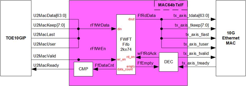
Figure 2‑3 MAC64bTxIF Block Diagram
The Tx interface characteristics of 10G Ethernet MAC and TOE10G-IP differ. TOE10G-IP requires continuous data transmission for one packet, while the AMD Xilinx 10G Ethernet MAC does not support this feature. The EMAC may de-assert the ready signal to pause data reception before the end of the packet.
MAC64bTxIF is designed to buffer transmitted data from TOE10G-IP when the EMAC is not ready to receive new data. The FIFO depth is 2048, allowing it to store at least one data packet during pausing periods. The maximum packet size in the TOE10G-IP reference design is 8960 bytes, or 1120 units of 64-bit data. Therefore, a depth of 2048 is sufficient to store one packet. The FIFO is a First-Word Fall-Through (FWFT) FIFO, so the read data is immediately available upon asserting the read enable signal.
The operation of MAC64bTxIF is divided into two parts. The first part involves transferring a packet from TOE10GIP to the FIFO. The second part involves transferring a packet from the FIFO to the 10G Ethernet MAC. Timing diagrams for each part are shown in Figure 2‑4 and Figure 2‑5.
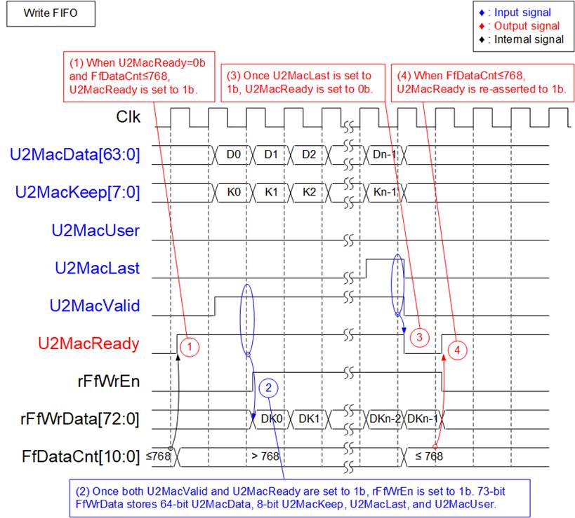
Figure 2‑4 Timing Diagram for Data Transfer from TOE10G-IP to FIFO
1) Before asserting U2MacReady to 1b for receiving a new packet from the user, two conditions must be met. First, the free space in the FIFO must be sufficient to store the maximum packet size of 9014 bytes. For simplified monitoring logic, the upper bit of FfDataCnt is read to confirm that the amount of data in the FIFO does not exceed 768 (indicating that the free space exceeds 1151 units of 64-bit data). Second, the previous packet must be completely transferred, which is indicated by U2MacReady being 0b.
2) The user starts transmitting a packet by asserting U2MacValid to 1b. The input signals from the user (U2MacData, U2MacKeep, U2MacLast, and U2MacUser) are valid and stored in the FIFO when both U2MacValid and U2MacReady are asserted to 1b. Subsequently, the inputs are stored in the FIFO by asserting rFfWrEn to 1b. The 74-bit write data to the FIFO consists of 64-bit data (U2MacData), 8-bit byte enable (U2MacKeep), end flag (U2MacLast), and error flag (U2MacUser).
3) After receiving the final data of a packet (U2MacLast=1b and U2MacValid=1b), U2MacReady is de-asserted to 0b to pause data transmission for reading FfDataCnt.
4) If FfDataCnt shows that the free space in the FIFO is sufficient, U2MacReady will be re-asserted to 1b in the next cycle.
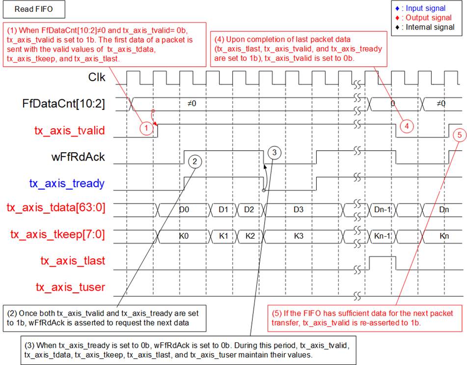
Figure 2‑5 Timing Diagram for Data Transfer from FIFO to EMAC
1) The transmission of a new packet begins when the FIFO contains some data (FfDataCnt[10:2] ≠ 0) and no packet is currently transmitting (tx_axis_tvalid=0b). To initiate data transmission, tx_axis_tvalid is set to 1b, along with the valid output signals to EMAC: 64-bit tx_axis_tdata, 8-bit tx_axis_tkeep, tx_axis_tlast, and tx_axis_tuser.
2) If data is successfully transmitted to EMAC (tx_axis_tvalid=1b and tx_axis_tready=1b), wFfRdAck is asserted to ‘1’ to retrieve the next data from FIFO.
3) If tx_axis_tready is de-asserted to 0b, wFfRdAck will be de-asserted to 0b to pause reading new data from the FIFO. Consequently, all output signals sent to EMAC hold their values until EMAC re-asserts tx_axis_tready to 1b.
4) After the final data of a packet is completely transferred (tx_axis_tlast=1b and tx_axis_tready=1b), tx_axis_tvalid is de-asserted to 0b to pause data transmission and check the data size in FIFO for transferring the next packet.
5) The next packet is transmitted when the FIFO has enough data, returning to step 1 to transmit the new packet.
MAC64bRxIF
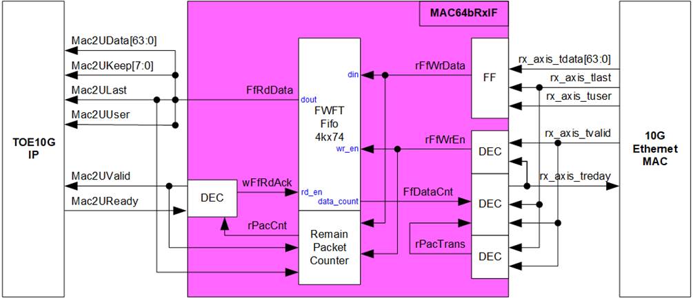
Figure 2‑6 MAC64bRxIF Block Diagram
When the 10G Ethernet MAC is connected to the Aquantia PHY to support both 1G Ethernet and 10G Ethernet, the Rx interface of the 10G Ethernet MAC may not guarantee continuous packet data transfer, as it can de-assert the valid signal before the last packet data transmission. To address this, the MAC64bRxIF is used to buffer a complete received packet before forwarding it to the TOE10G-IP, ensuring uninterrupted packet data transmission.
The FIFO depth inside MAC64bRxIF is 4096, which is sufficient for storing several Ethernet packets. Similar to MAC64bTxIF, it is a First-Word Fall-Through (FWFT) FIFO. The ‘Remain Packet Counter’ indicates the number of packets stored in the FIFO, increasing when a complete packet is received from EMAC and decreasing when a complete packet is forwarded to TOE10G-IP.
The operation of MAC64bRxIF is divided into two parts. The first part handles transferring a packet from EMAC to FIFO, and the second part handles transferring a packet from FIFO to TOE10G-IP. Timing diagrams of each part are displayed in Figure 2‑7 and Figure 2‑8.
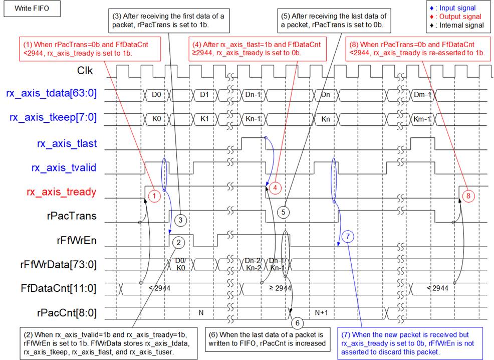
Figure 2‑7 Timing Diagram for Data Transfer from EMAC to FIFO
1) Read FfDataCnt to check the available free space in the FIFO. If FfDataCnt is less than 2944 (indicating that the free space in FIFO exceeds 1153), it is sufficient to store the maximum packet size of 9014 bytes. Additionally, rPacTrans must be equal to 0 to confirm that no packet is currently being transmitted. Once these conditions are met, assert rx_axis_tready to 1b to begin data reception from EMAC.
2) When rx_axis_tvalid is asserted to 1b to indicate the start of a new packet transfer, store the data and control signals from EMAC, including 64-bit rx_axis_tdata, 8-bit rx_axis_tkeep, rx_axis_tlast, and rx_axis_tuser, in the FIFO. Assert rFfWrEn to 1b to write the 74-bit data to the FIFO.
3) After the first data of a packet is received, assert rPacTrans to 1b until the end of packet is received. This can be used to monitor the packet transmission status.
4) If the final data of a packet is received and the free space size in the FIFO is insufficient (FFDataCnt≥2944), de-assert rx_axis_tready to 0b to pause data reception.
5) After the final data of a packet is received, de-assert rPacTrans to 0b to indicate that packet transmission status has changed from Busy to Idle.
6) After storing the final data of a packet in the FIFO (rFfWrEn=1b and rFfWrData[72]-last flag = 1b), increment rPacCnt, the counter that shows the total number of packets stored in the FIFO.
7) If the next packet is received while rx_axis_tready is still de-asserted to ‘0’, the received packet will be dropped and not be stored in the FIFO.
8) Re-assert rx_axis_tready to 1b when no packet is being transmitted and there is sufficient free space size in the FIFO.

Figure 2‑8 Timing Diagram for Data Transfer from FIFO to TOE10G-IP
1) Packet forwarding from the FIFO to TOE10G-IP begins when at least one packet is stored in the FIFO (indicated by rPacCnt, which shows the number of packets stored in the FIFO, being not equal to 0). Mac2UValid is asserted to 1b to start data transmission.
2) The read data output from the FIFO is used as the data and control signals sent to TOE10G-IP, i.e., 64-bit Mac2UData, 8-bit Mac2UKeep, Mac2ULast, and Mac2UUser. Mac2UValid is asserted to 1b until the end of packet. Therefore, the data and control signals of each packet are transferred continuously to TOE10G-IP.
3) After each packet data is completely transferred to TOE10G-IP (Mac2UValid=1b and Mac2UReady=1b), wFfRdAck is asserted to 1b to read the next data.
4) After the final data of a packet is transferred (Mac2ULast=1b and Mac2UValid=1b), Mac2UValid and wFfRdAck are de-asserted to 0b to pause packet transmission. Additionally, rPacCnt is decremented after completing the transfer of one packet.
2.3 TOE10G-IP
The TOE10G-IP implements the TCP/IP stack and offload engine. The user interface is divided into two signal groups: control signals and data signals. The control signals are managed via a Register interface that allows setting control registers and monitoring status signals. The data signals are accessed using a FIFO interface. For more detailed information, please refer to the datasheet.
https://dgway.com/products/IP/TOE10G-IP/dg_toe10gip_data_sheet_xilinx_en/
2.4 User Logic
The User Logic module provides an example logic of connecting to three user interfaces of the TOE10G-IP: the Register interface for control/status signals, the TxFIFO interface for transmitting data, and the RxFIFO interface for receiving data. The internal logic of the User Logic module is divided into three parts: the State machine for the Register interface (labelled as no.1 in Figure 2‑9), the Pattern Generator for the TxFIFO interface (labelled as no.2 in Figure 2‑9), and the Pattern Verification for the RxFIFO interface (labelled as no.3 in Figure 2‑9). More details on each part are described in the subsequent sections.
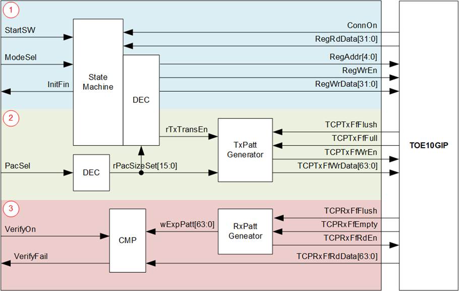
Figure 2‑9 User Logic Block Diagram
The State machine for the Register interface
The User Logic operation is initiated when the ‘StartSW’ signal is triggered by pressing the push button on the FPGA board. Following this, the Register I/F is used to configure the network parameter values until the TOE10G-IP initialization process is completed, as indicated by InitFin signal being set to 1b.
Data transfer begins after the PC establishes a TCP connection by executing the test application. The State machine determines the data transfer direction (send or receive) based on the ‘ModeSel’ signal, which is input by the user. The details of this State machine are displayed in Figure 2‑10.
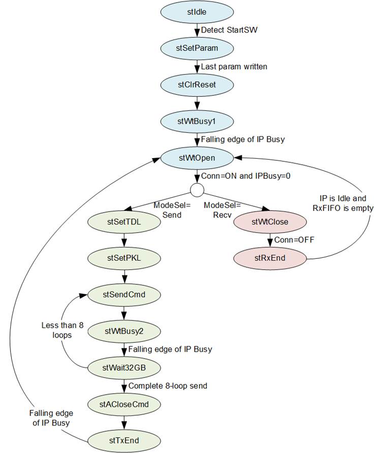
Figure 2‑10 State Machine
The functions of the State machine can be categorized to three phases: Initialization, Data Transmission, and Data Reception, hi-lighted by blue, green, and red colors in Figure 2‑10.
Initialization
1) stIdle: After the reset is de-asserted, the state machine enters this state to wait for a start command from the user. Once it is received (StartSW=1b), the state changes to stSetparam.
2) stSetParam: In this state, the TOE10G-IP registers are set with the following values.
· Source MAC address (SML/SMH) : 0x000102030405
· Target IP address (DIP) : 192.168.7.25
· Source IP address (SIP) : 192.168.7.42
· Target port number (DPN) : 4001
· Source port number (SPN) : 4000
· Total data length (TDL) : 1456
· Timeout (TMO) : 312500000
· Packet length (PKL) : 1456
· Transmission mode (PSH) : 100b
· Window update gap in 1 KB (WIN) : 16
Upon the completion of parameter setup, the state changes to stClrReset
3) stClrReset: In this state, the RST register of the TOE10G-IP is set to 0b to start the initialization process. After this, the state transitions to stWrBusy1.
4) stWtBusy1: This state waits for the completion of the TOE10G-IP initialization process by polling the falling edge of the TOE10G-IP’s busy flag (RegRdData[0] of the CMD register). Once it is detected, the state moves to stWtOpen and asserts the InitFin signal to 1b.
5) stWtOpen: This state waits until the TCP connection has been successfully established by the PC, indicated by ConnOn being set to 1b. Following this, the state transitions to others for transmitting or receiving data, depending on ‘ModeSel’ value.
Data Transmission
1) stSetTDL: This state sets the TDL registers to 0xFFFFFF8 (4GB) for transmitting 4GB of data. Additionally, the ‘rTxTranEn’ signal is set to 1b to initiate the Pattern Generator operation.
2) stSetPKL: In this state, the value of the PacSel signal is read to set the PKL registers. If PacSel equals zero, PKL is set to 1456. Otherwise, PKL is set to 8960.
3) stSendCmd: This state sets the CMD register with the ‘Send data’ value, prompting the TOE10G-IP to initiate data transmission.
4) stWtBusy2: This state is used to wait for the completion of 4GB data transmission by monitoring the falling edge of the TOE10G-IP’s busy flag (RegRdData[0] of the CMD register).
5) stWait32GB: This state checks if the total transmission loop equals 8 or 32 GB of transmitted data. If it has not been reached, the state re-enters stSendCmd to iterate another 4 GB data transmission. Otherwise, the state changes to stACloseCmd.
6) stACloseCmd: This state sets the CMD register with the ‘Active close’ value, prompting the TOE10G-IP to initiate connection termination.
7) stTxEnd: This state waits for the completion of the connection termination by monitoring the falling edge of the TOE10G-IP’s busy flag (RegRdData[0] of the CMD register). Following this, the state returns to stWtOpen to wait for the next connection establishment.
Data Reception
1) stWtClose: This state waits until all data has been received completely and the connection has been terminated, indicated by the ConnOn being equal to 0b. Following this, the state transitions to stRxEnd.
2) stRxEnd: This state waits until all data has been received completely, indicated by the ‘TCPRxFfEmpty’ being set to 1b, and the TOE10G-IP returns to the idle condition, indicated by the TOE10G-IP’s busy flag (RegRdData[0]= 0b of the CMD register) being set to 0b. The state then transitions back to stWtOpen to wait for the next connection establishment.
The Pattern Generator for the TxFIFO interface
The Pattern Generator is enabled by the ‘rTxTransEn’ signal. It generates a 32-bit
fixed value, starting from zero, for each packet. Once the last packet data has
been generated, the 32-bit fixed value is incremented. The packet size is determined
by ‘PacSel’ value. This data generation continues until the TCP connection is
closed. Figure
2‑11 illustrates the timing diagram of the Pattern
Generator operation.
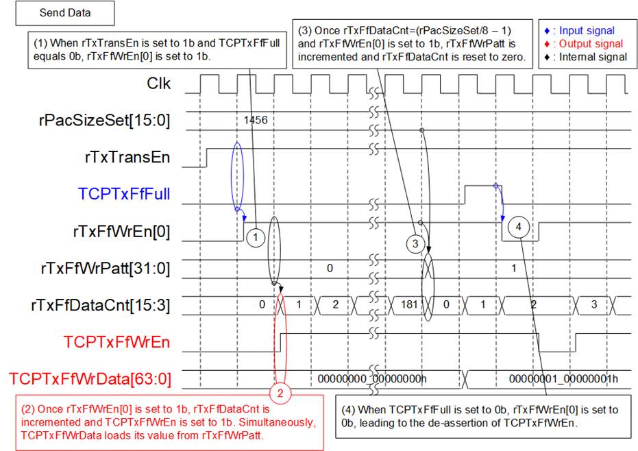
Figure 2‑11 The Pattern Generator Timing Diagram
1) When the state machines enters the ‘Send Data’ phase, indicated by ‘rTxTransEn’ being set to 1b, and the TOE10G-IP has free space for receiving data, indicated by ‘TCPTxFfFull’ being set to 0b, new data is written to the TOE10G-IP by setting ‘rTxFfWrEn[0]’ to 1b. During the assertion of ‘rTxFfWrEn[0]’, the data counter (rTxFfDataCnt) is incremented to indicate the amount of data in this packet.
2) One clock cycle after the assertion of ‘rTxFfWrEn[0]’, the actual data is written to the TOE10G-IP by setting ‘TCPTxFfWrEn’ to 1b, along with the preparation of 64-bit write data (TCPTxFfWrData) which is loaded from the ‘rTxFfWrPatt’ signal.
3) When the value of ‘rTxFfDataCnt’ matches (the packet size/8 – 1), ‘rTxFfWrPatt’ is incremented to the next value to be the write data of the next packet.
4) During data transmission, if the buffer inside the TOE10G-IP becomes full, indicated by TCPTxFfFull being set to 1b, the data transmission is paused by setting rTxFfWrEn[0] to 0b. Data transmission continues until ‘rTxTransEn’ is set to 0b, which occurs when the state returns to stWtOpen.
The Pattern Verification for the RxFIFO interface
The Pattern Verification always monitors the available data from the TOE10G-IP,
indicated by ‘TCPRxFfEmpty’ being set to 0b. If the verification is enabled (‘VerifyOn’=1b),
the received data is compared with the expected value, which is 32-bit
incremental data. While the test pattern of the Pattern Generator is
incremented at the end of each packet, the test pattern of the Pattern
Verification is incremented in every data transmission. The ‘VerifyFail’ is set
to 1b if the received data mismatches the expected value. This failure flag can
be cleared by asserting the reset signal. Figure 2‑12 illustrates the timing
diagram of the Pattern Verification operation.
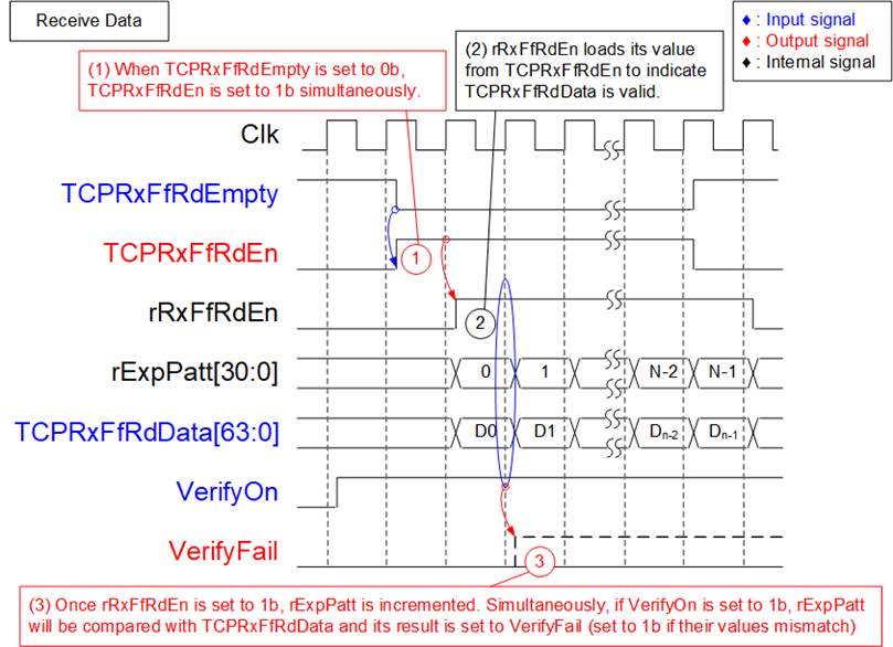
Figure 2‑12 The Pattern Verification Timing Diagram
1) When there is available data for reading, indicated by TCPRxFfRdEmpty being set to 0b, ‘TCPRxFfRdEn’ is immediately set to 1b to retrieve data from the TOE10G-IP.
2) One clock cycle after asserting ‘TCPRxFfRdEn’, ‘TCPRxFfRdData’ is valid for reading. ‘rRxFfRdEn’ is set to 1b to indicate the received data’s validity and enable the data comparison with ‘rExpPatt’. Additionally, the assertion of ‘rRxFfRdEn’ is used to increase the ‘rExpPatt’ value for comparison with the next received data.
Note: The 64-bit expected value is created by using two ‘rExpPatt’ signals appended by 0b and 1b to generate two sets of 32-bit incremental data.
3) The result of the data comparison is loaded to the ‘VerifyFail’ signal. It is set to 1b if the value of ‘TCPRxFfRdEn’ mismatches the value of ‘rExpPatt’.
3 Test Software on PC
Two test applications are used within this demo: ‘recv_tcp_client_10G’ and ‘send_tcp_client_10G’. Both applications operate in Client mode.
3.1 ‘recv_tcp_client_10G’ for Send Data Test
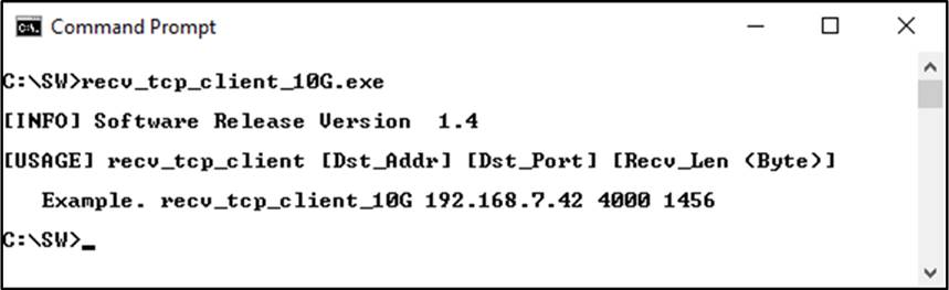
Figure 3‑1 ‘recv_tcp_client_10G’ application usage
The ‘recv_tcp_client_10G’ application is executed to receive TCP data on a PC. It requires three parameters, which must match those set on the FPGA. The details of each parameter are as follows.
1) Dst_Addr : The IP address of the FPGA (Default is 192.168.7.42)
2) Dst_Port : The port number of the FPGA (Default is 4000)
3) Recv_Len : The data length of one 32-bit incremental pattern.
The valid value in this reference design is 1456 or 8960.
The sequence of the test application is described as follows.
1) Obtain and verify the user’s input parameters.
2) Create a socket, set the socket options, and specify the socket memory size.
3) Allocate 512KB memory for the receive buffer.
4) Establish a new connection using the FPGA IP address and FPGA port number.
5) Wait for the data to be stored in the receive buffer, read it, and increase the total amount of received data.
6) Verify the received data by the fixed pattern, which increments its value every ‘Recv_Len’ size of data. Print an error message if the data is incorrect.
7) Print the total amount of received data every second.
8) Repeat steps 5) – 7) until the connection is closed by the other device.
9) Calculate the total performance and print the result on the console.
10) Close the socket.
11) Iterate step 4) – 10) forever until the application is closed.
3.2 ‘send_tcp_client_10G’ for Receive Data Test
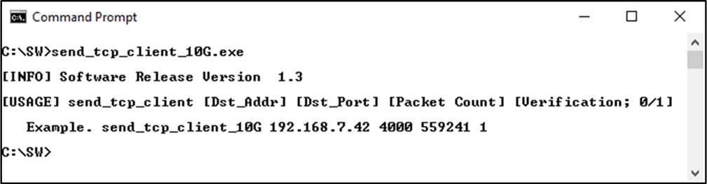
Figure 3‑2 ‘send_tcp_client_10G’ application usage
The ‘send_tcp_client_10G.exe’ application is executed to send TCP data from a PC. It requires four parameters, which must match those set on the FPGA. The details of each parameter are as follows.
1) Dst_Addr : The IP address of the FPGA (Default is 192.168.7.42)
2) Dst_Port : The port number of the FPGA (Default is 4000)
3) Packet Count : The total transfer size in 60 KB units. The valid range value is 1-559241.
4) Verifications : 0 – Generate dummy data for non-verification test.
: 1 - Generate incremental data for verification test.
The sequence of the test application is described as follows.
1) Obtain and verify the user’s input parameters.
2) Create a socket, set the socket options, and specify the socket memory size.
3) Establish a new connection using the FPGA IP address and FPGA port number.
4) Allocate 2 MB memory for the send buffer.
5) Generate the incremental test pattern to the send buffer if the dummy pattern is not selected.
6) Send the data out and read the total amount of sent data through the socket function.
7) Calculate the remaining transfer size.
8) Print the total transfer size every second.
9) Repeat steps 5) – 8) until the remaining transfer size is 0.
10) Calculate the total performance and print the result on the console.
11) Close the socket and free the memory.
4 Revision History
|
Revision |
Date |
Description |
|
1.01 |
12-Jul-24 |
Add MAC64bTxIF and MAC64bRxIF |
|
1.00 |
18-Aug-14 |
Initial Release |
Copyright: 2014 Design Gateway Co,Ltd.