TOE1G-IP Two-Port Demo Instruction
Rev1.3 8-Aug-23
1 Environment Setup
The TOE1G-IP Two-port demo requires the use of the following the hardware and software components.
1) FPGA Development boards: AC701/KC705/ZC706/KCU105
2) PC with 1 Gigabit Ethernet interface or equipped with 1 Gigabit Ethernet card
3) 1Gb Ethernet cable: Cat5e or Cat6 cable
Note: When using ZC706, an SFP+ to RJ45 adapter is required to connect to SFP+ connector.
4) A micro USB cable for programming the FPGA and connecting the FPGA board to the PC
5) A micro/mini USB cable for Serial console, connecting the FPGA board to the PC.
6) The test applications, “send_tcp_client.exe” and “recv_tcp_client_single.exe”, provided by Design Gateway for running on the PC
7) Serial console software such as TeraTerm installed on the PC. The console settings are as follows: Baud rate=115,200, Data=8-bit, Non-parity, and Stop=1.
8) Vivado tool for programming FPGA, installed on PC
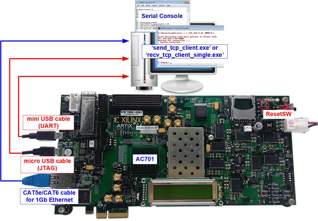
Figure 1‑1 TOE1G-IP Two-port demo environment setup on AC701
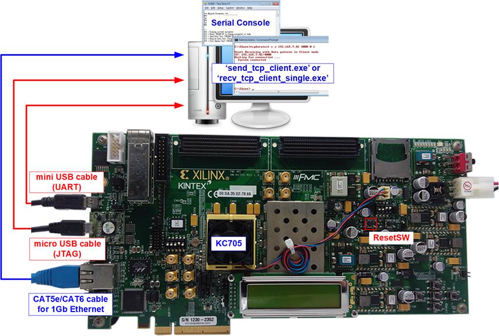
Figure 1‑2 TOE1G-IP Two-port demo environment setup on KC705
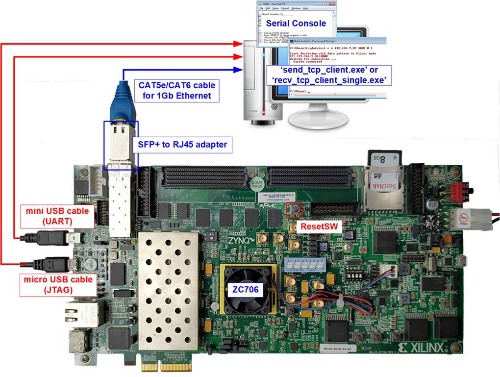
Figure 1‑3 TOE1G-IP Two-port demo environment setup on ZC706

Figure 1‑4 TOE1G-IP Two-port demo environment setup on KCU105
The FPGA board includes four LEDs that indicate additional status during the test operation. In this demo, these LEDs are mapped to the internal status signals when operating the fast connection using TOE1G-IP. However, there is no LED status mapped to indicate the slow connection operation. Nevertheless, the user can monitor the test progress from the console. The description of each LED is provided in Table 1‑1.
Table 1‑1 LED Definition
|
GPIO LED |
ON |
OFF |
|
0 |
The TOE1G-IP connection is established. |
No TOE1G-IP connection available |
|
1/R |
Transferring data to TOE1G-IP |
No data transfer to TOE1G-IP |
|
2/C |
Transferring data from TOE1G-IP |
No data transfer from TOE1G-IP |
|
3/L |
Received data available in TOE1G-IP |
No remaining received data in TOE1G-IP |
2 PC Setup
Before running the demo, it requires to set up the PC environment. The steps to prepare the PC environment are described in “PC Setup” section of “dg_toe1gip_cpu_instruction” document, available at following link.
https://dgway.com/products/IP/TOE1G-IP/dg_toe1gip_cpu_instruction/
3 FPGA Setup
This section provides a step-by-step to prepare the FPGA board for running the demo.
1) On the Zynq device board (ZC706), ensure that the DIP switch setting is correct. For ZC706, set SW11=all OFF to configure PS from JTAG and set SW4[1:2]=[OFF ON] to connect JTAG with USB-to-JTAG interface, as shown in Figure 3‑1.
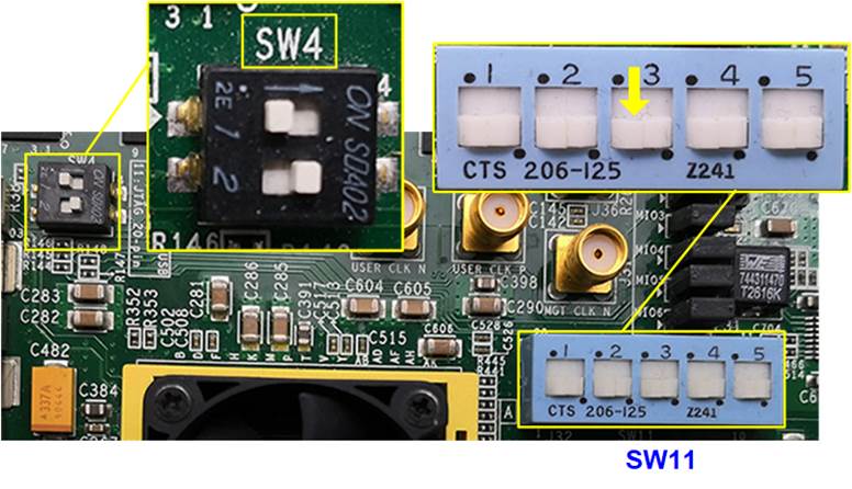
Figure 3‑1 SW11 setting to configure PS from JTAG on ZC706 board
2) Connect USB cables from FPGA board to PC for JTAG programming and Serial console.
a) For 7-series boards, use a micro USB cable for JTAG programming and a mini USB cable for Serial console.
b) For UltraScale board, use two micro USB cables for JTAG programming and Serial console.
3) On UltraScale board (KCU105), after connecting the USB cables to the PC, the system will detect an additional COM port. Select the Standard COM port.
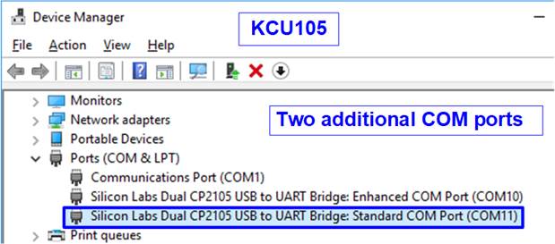
Figure 3‑2 Additional COM port on UltraScale board
4) Open Serial console on PC and configure the following settings: Buad rate=115200, Data=8-bit, Non-parity, and Stop=1.
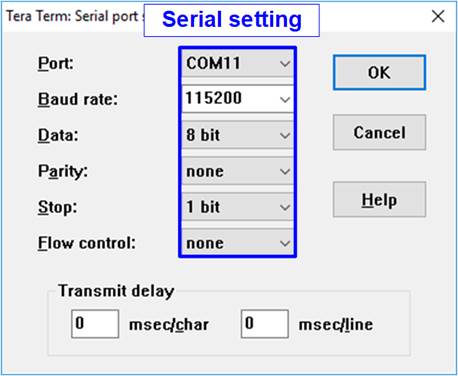
Figure 3‑3 Serial console setting
5) Connect Ethernet cable between FPGA development board and PC.
Note: For ZC706, connect an SFP to RJ45 adapter into the SFP+ connector before connecting the Ethernet cable.
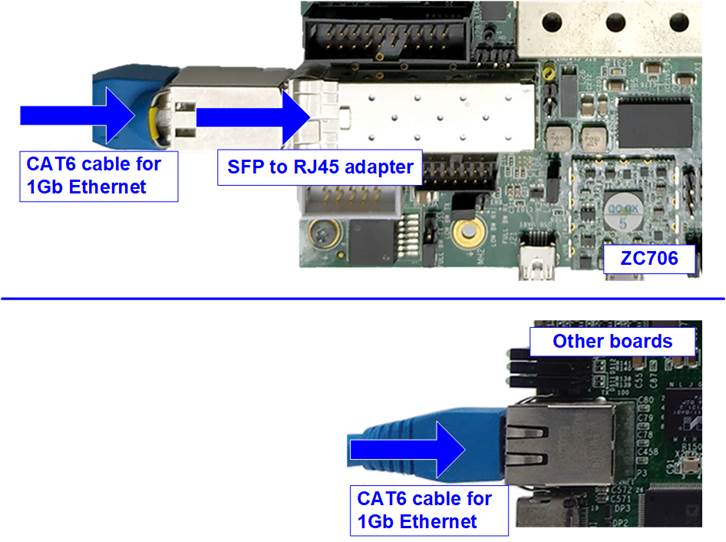
Figure 3‑4 Ethernet cable connecting to FPGA board
6) Power on the FPGA board and download the configuration file, including firmware, to FPGA board.
a) For Zynq device board (ZC706), open Vivado TCL shell and change the current directory to “download” folder, which includes demo configuration file. Run the bat file to start downloading the configuration file and firmware, as shown in Figure 3‑5.
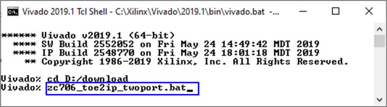
Figure 3‑5 Download configuration file by bat file
b) For other FPGA boards, the FPGA can be configured using Vivado, as shown in Figure 3‑6.
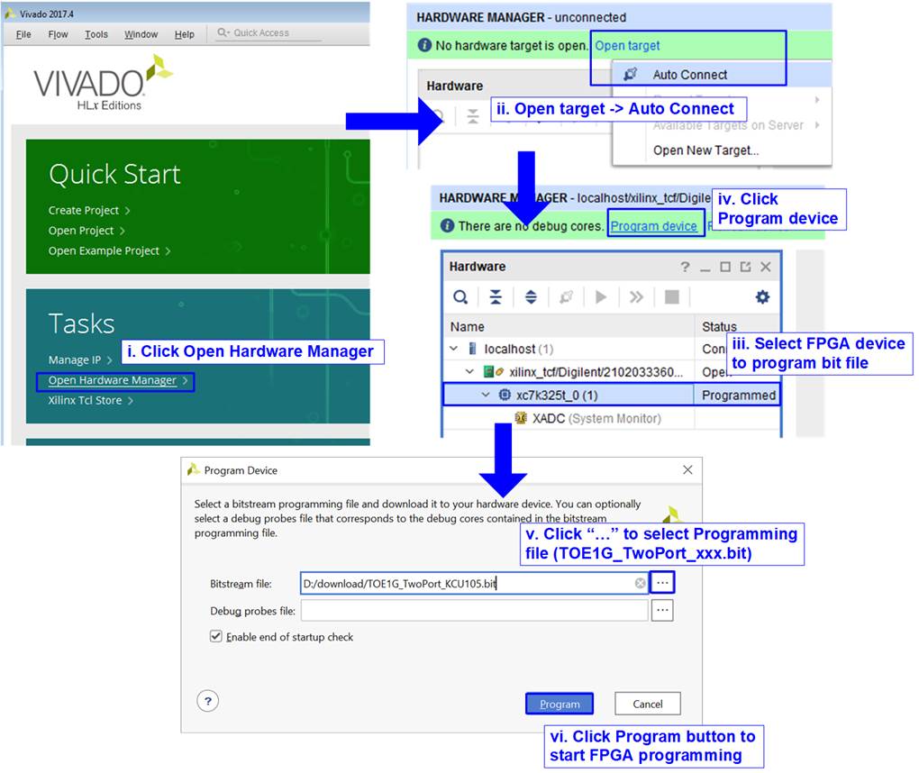
Figure 3‑6 Download configuration file by Vivado tool
7) On the Serial console, the welcome message is displayed. The console displays “Wait IP initialize” while the IP operates the initialization process. After the initialization is completed, the main menu for running the test is displayed. Three test menus can be selected which describes in more details in the next section.
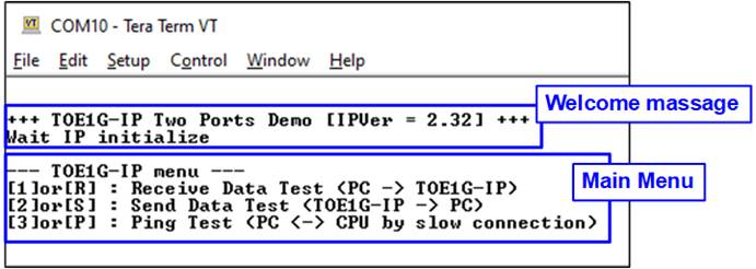
Figure 3‑7 Main Menu
4 Test menu
The hardware system can concurrently support data transfer in both TX and RX directions for fast connection. Additionally, it allows to enable the fast connection and the slow connection simultaneously. However, the test menu only allows the execution of one option at a time to simplify the test sequence. This section provides examples for running each test option.
4.1 Receive Data Test
To execute the Receive data test using TOE1G-IP, select option ‘1’ from the menu. This test involves transmitting test data from the PC to the FPGA (TOE1G-IP). On the PC side, run the “send_tcp_client.exe” application via the Command prompt with specific parameters to transmit the test data, using incremental or dummy pattern and a selected transfer size. Once the data transfer is completed, the application displays the test performance result. The steps for running the Receive data test are below.
1) Upon entering [1] or [R] on the Serial console, the message “Please start send_tcp_client …” will be displayed. During this step, if the user enters any key to the Serial console, the operation will be cancelled (as shown in Figure 4‑5).
2) Open the “Command prompt” and browse to the directory where “send_tcp_client” is located. Run the “send_tcp_client” command with the following parameters.
>> send_tcp_client <Dst_Addr> <Dst_Port> <Packet Count > <Test pattern>
a) Destination IP address: IP address of the TOE1G-IP (192.168.11.42)
b) Destination port: The port number of TOE1G-IP (4000)
c) Packet Count: Total number of 16KB packets to send to FPGA. Valid value range is 1 – 262143, allowing a maximum transfer length of 4,294,950,912 (262143 x 16384) bytes.
d) Test pattern: [0]-Dummy data, [1]-32-bit incremental data. Option ‘0’ does not require the CPU to prepare the test data, resulting in lower PC resource usage compared to option ‘1’. In certain PCs, option ‘0’ demonstrates better performance than option ‘1’.
3) After executing “send_tcp_client”, the connection is established, and the data transfer begins. Both the Serial console and Command prompt will display “…” during the data transfer process.
4) Once the PC completes sending the data and closes the connection, the FPGA console will show “Transfer complete” along with the total received size. The Command prompt will display the total transfer size and performance. If the total transfer size exceeds the allocated DDR area, the test operation is completed at this step (as shown in Figure 4‑1). Otherwise, proceed to the next step (as shown in Figure 4‑2).
5) The Serial console shows the option to verify data or not. If the user enters ‘Y’, the data verification is initiated. Otherwise, the operation is completed without verifying data (as shown in Figure 4‑4).
6) If the read data mismatches the expected value during data verification, an error message is displayed (as shown in Figure 4‑3). Once the data verification is completed, the system returns to the main menu.

Figure 4‑1 Receive data test when transfer size exceeds the allocated DDR area
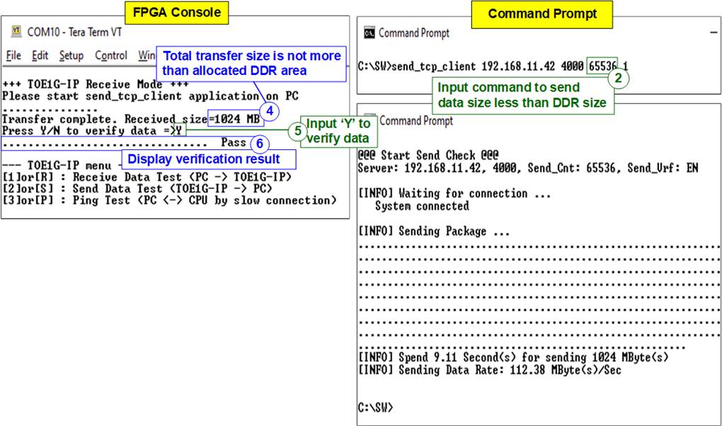
Figure 4‑2 Receive data test when transfer size does not exceed the allocated DDR area
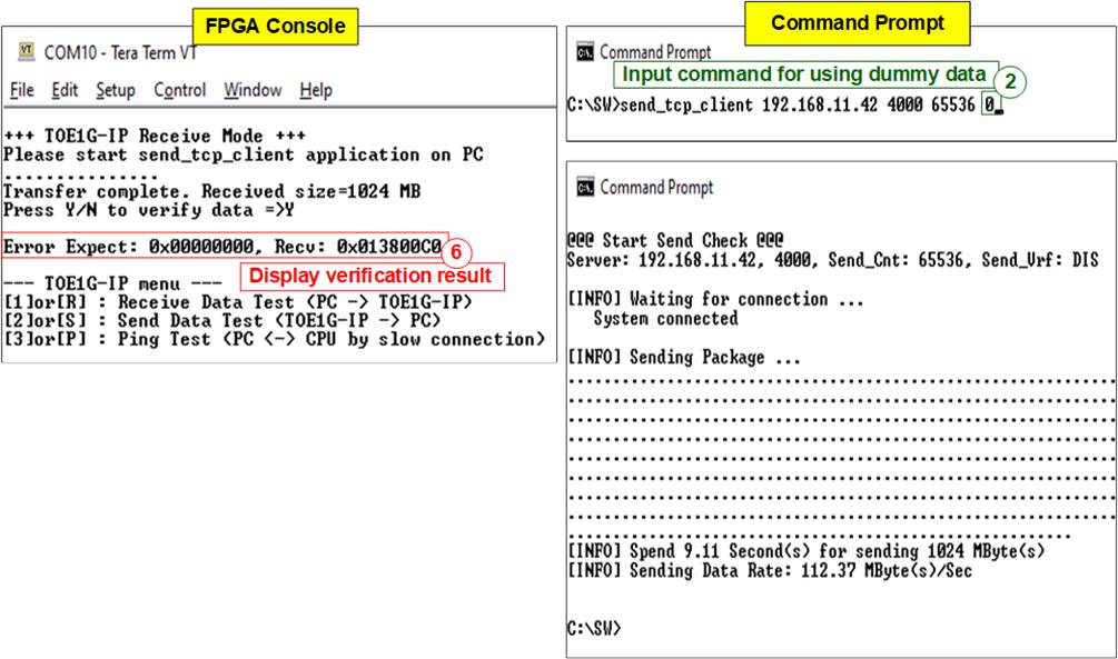
Figure 4‑3 Receive data test when the data verification fails

Figure 4‑4 Receive data test without data verification
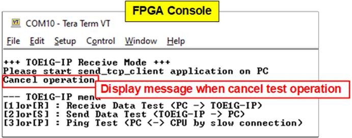
Figure 4‑5 The operation is cancelled in step 1)
4.2 Send Data Test
To execute the Send data test using TOE1G-IP, select option ‘2’ from the menu. This test involves transmitting test data from the FPGA (TOE1G-IP) to the PC. On the PC side, run the “recv_tcp_client_single.exe” application via the Command prompt with specific parameters to receive the test data. The application provides an additional option to enable or disable data verification. After completing the data transfer, the test performance result is displayed. Follow the steps below to run the Send data test.
1) Upon entering [2] or [S] on the Serial console, the menu to set the test parameters of Send data test is displayed. The user enters two or three parameters as follows.
a) Packet size: [0]-1460 byte (normal frame), [1]-8960 byte (jumbo frame)
b) Total transfer length: Valid range is 1 – 0xFFFFFFFF. If the total transfer size exceeds the allocated DDR area, proceed to step 2) (as shown in Figure 4‑6 - Figure 4‑7). Otherwise, continue to step c).
c) Prepare test data: This input is displayed only when the total transfer length does not exceed the allocated DDR area. Enter ‘Y’ to fill increment test pattern or any other key to fill dummy data (as shown in Figure 4‑8 - Figure 4‑9).
2) The Serial console displays the recommended parameters for “recv_tcp_client_single” test application. The operation is paused to wait for the connection establishment from the PC.
3) Open the “Command prompt” and browse to the directory where “recv_tcp_client_single” is located. Run the “recv_tcp_client_single” command with the following parameters.
>> recv_tcp_client_single <Dst_Addr> <Dst_Port> <Recv_Len> <Verification>
a) Destination IP address: IP address of TOE1G-IP (192.168.11.42)
b) Destination port: The port number of TOE1G-IP (4000)
c) Receive Length: Threshold value of the received data size to initiate the function for reading data from the buffer. Generally, this value is configured to be the packet size, set on the Serial console. However, if total transfer length is less than the packet size, this value should be equal to the total transfer size.
d) Verification: [0]-No verification, [1]-Enable data verification. Option ‘0’ does not require the CPU to verify the test data, resulting in lower PC resource usage compared to option ‘1’. In certain PCs, option ‘0’ demonstrates better performance than option ‘1’. Option ‘1’ can be selected only when the step 1) chooses the option to prepare incremental data, not dummy data. The data verification will fail if the FPGA sends dummy data, but the PC enables data verification (as shown in Figure 4‑10).
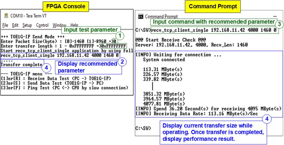
Figure 4‑6 Send data test using dummy data at 1460-byte packet without data verification

Figure 4‑7 Send data test using dummy data at 8960-byte packet without data verification
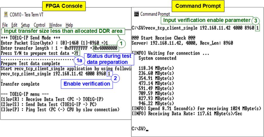
Figure 4‑8 Send data test using incremental data at 8960-byte packet with data verification

Figure 4‑9 Send data test using dummy data at 8960-byte packet without data verification
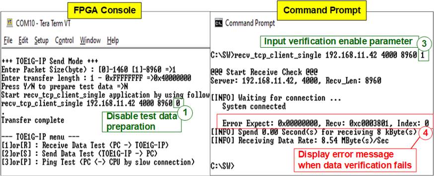
Figure 4‑10 Send data test and data verification fails
(mismatch setting by sending dummy data but enabling data verification)
4.3 Ping Test
To execute data transfer using the slow connection, which is processed by the CPU inside the FPGA, select option ‘3’ from the menu. This test involves demonstrating small-sized data transfer in both directions using the “Ping” command. Follow the steps below to run the Ping test.
1) Upon entering [2] or [P] on the Serial console, the message “Please start run Ping command on PC” will be displayed.
2) Open the “Command prompt” and execute the “Ping command” with the following format.
>> ping 192.168.11.42 (IP address assigned to FPGA)
3) The Command prompt will display the result of Ping command. After the operation is completed, the user can exit the test and return to main menu by entering any key on Serial console.
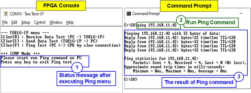
Figure 4‑11 Ping command Test
5 Revision History
|
Revision |
Date |
Description |
|
1.3 |
27-Jul-23 |
Add KCU105 support |
|
1.2 |
2-Sep-16 |
IP core product renamed from TOE2-IP to TOE1G-IP |
|
1.1 |
29-Dec-15 |
Add AC701 support |
|
1.0 |
16-Jan-15 |
Initial version release |