FPGA Setup for TOE/UDP1G IP with CPU Demo
Rev2.0 4-Jul-23
1 Test environment setup when using FPGA and PC
2 Test environment setup when using two FPGAs
This document describes how to setup FPGA board and prepare the test environment for running TOE1G-IP or UDP1G-IP demo. The user can setup two test environments for transferring TCP data or UDP data via 1Gb Ethernet connection by using TOE1G-IP or UDP1G-IP, as shown in Figure 1‑1.
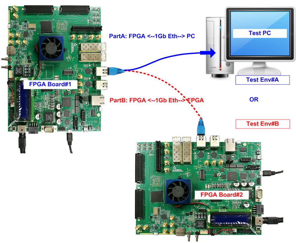
Figure 1‑1 Two test environments for running the demo
First uses one FPGA board and Test PC with 1Gb Ethernet card for transferring the data. Test PC runs test application, i.e., tcpdatatest (half-duplex test for TOE1G-IP), tcp_client_txrx_40G for (full-duplex test for TOE1G-IP) or udpdatatest (test application for UDP1G-IP). Also, NiosII command shell is run on Test PC to be user interface console.
Second uses two FPGA boards which may be different board or the same board. Both boards run TOE1G-IP or UDP1G-IP demo with assigning the different initialization mode (Client for Server) for transferring data.
1 Test environment setup when using FPGA and PC
Before running the test, please prepare following test environment.
- FPGA development boards:
- Arria 10 SoC Development Kit
- Arria 10 GX Development Kit
- Arria V GX FPGA Starter Kit
- Cyclone 10 GX FPGA Development board
- Cyclone V GT FPGA Development Kit
- Cyclone V E FPGA Development Kit
- PC with 1 Gigabit Ethernet or connecting with 1 Gigabit Ethernet card
- 1Gb Ethernet connection: Cat5e or Cat6 cable for between FPGA and PC/FPGA
- USB cable for FPGA programming and JTAG UART, connecting between FPGA board and PC. USB cable type of each board is as follows.
- micro USB cable:
Arria 10 SoC Development Kit
Arria 10 GX Development Kit
Cyclone 10 GX Development Kit
- USB-AB cable:
Arria V GX Starter Kit
Cyclone V GT FPGA Development Kit
Cyclone V E FPGA Development Kit
- QuartusII programmer for programming FPGA and NiosII command shell, installed on PC

Figure 1‑1 TOE1G-IP/UDP1G-IP with CPU demo (FPGA <-> PC) on Arria10 SoC
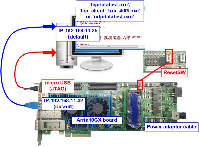
Figure 1‑2 TOE1G-IP/ UDP1G-IP with CPU demo (FPGA <-> PC) on Arria10 GX

Figure 1‑3 TOE1G-IP/UDP1G-IP with CPU demo environment setup on Cyclone10 GX
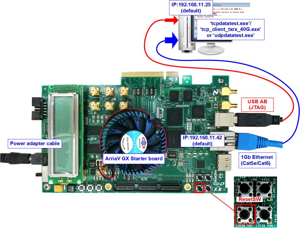
Figure 1‑4 TOE1G-IP/UDP1G-IP with CPU demo environment setup on ArriaV GX Starter
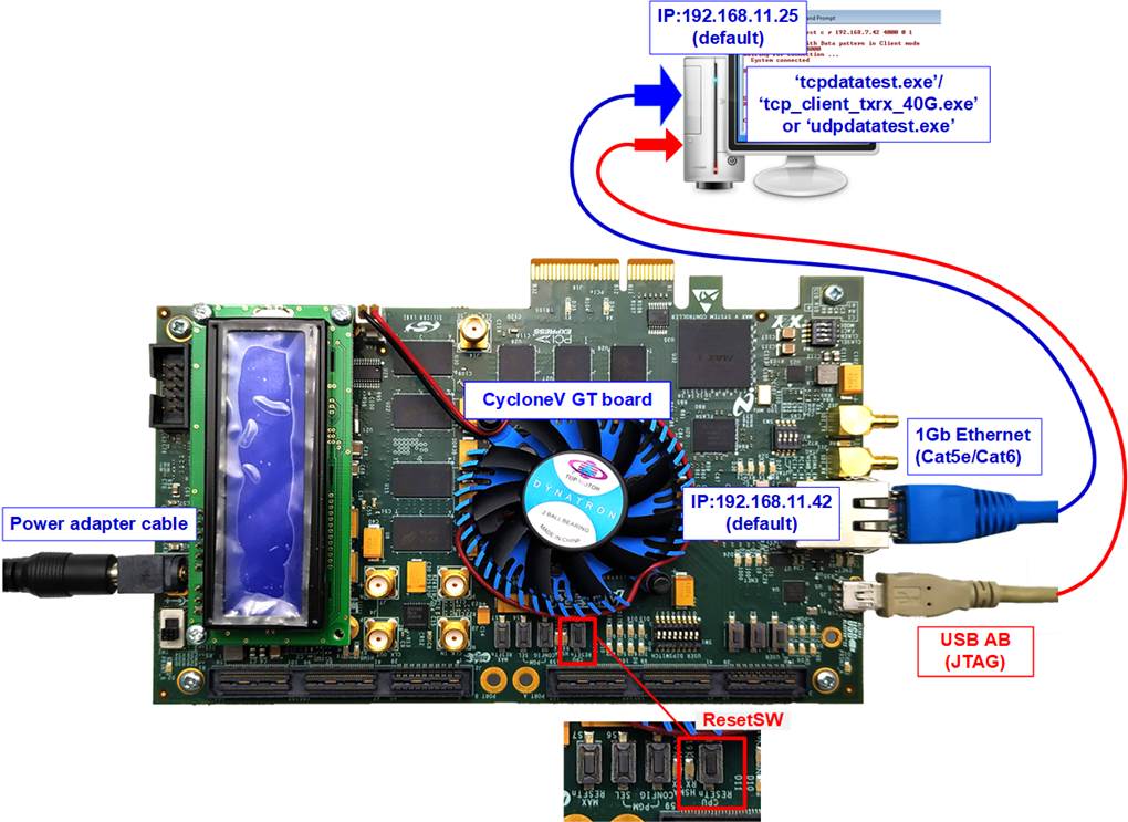
Figure 1‑5 TOE1G-IP/UDP1G-IP with CPU demo environment setup on CycloneV GT
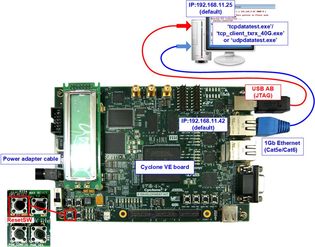
Figure 1‑6 TOE1G-IP/UDP1G-IP with CPU demo environment setup on CycloneV E
The step to setup test environment by using FPGA and PC is described in more details as follows.
1) Turn off power switch and connect power supply to FPGA board.
2) Connect USB cable, micro USB, or USB AB cable, depending on FPGA board, between FPGA board and PC for FPGA configuration and JTAG UART.
3) Connect CAT5e/CAT6 cable between PC and Ethernet connection of FPGA board. User must use the right port when FPGA board has two 1Gb Ethernet ports.

Figure 1‑7 Power, USB, and Ethernet connection
4) Turn on power switch on FPGA board.
5) Open QuartusII Programmer to program FPGA through USB-1 by following step.
a) Click “Hardware Setup…” to select USB-BlasterII[USB-1].
b) Click “Auto Detect” and select FPGA device.
c) Select FPGA device icon.
d) Click “Change File” button, select SOF file in pop-up window, and click “open” button
e) Check “program”
f) Click “Start” button to program FPGA
g) Wait until Progress status is equal to 100%
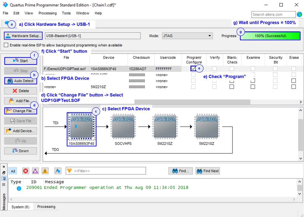
Figure 1‑8 FPGA Programmer
6) On NiosII command shell,
a. Type “nios2-terminal”.
b. Input ‘0’ to initialize TOE1G-IP/UDP1G-IP in client mode (ask PC MAC address by sending ARP request).
c. Default parameter in client mode is displayed on the console.
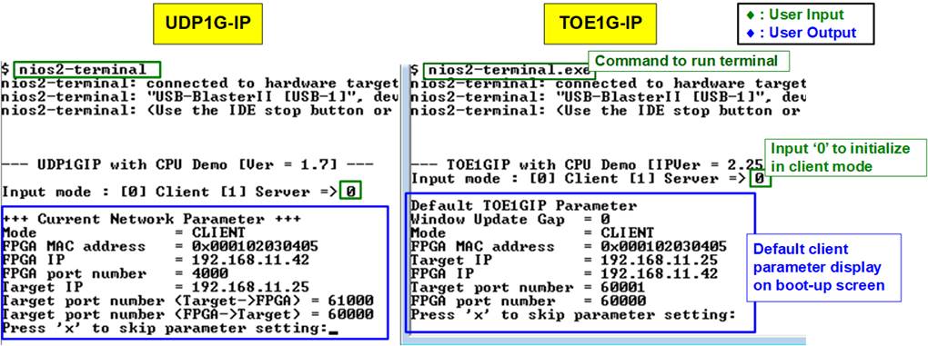
Figure 1‑9 Message after system boot-up
d. User enters ‘x’ to skip parameter setting for using default parameters to begin system initialization, as shown in Figure 1‑10. If user enters other keys, the menu for changing parameter is displayed, similar to “Reset TCPIP/UDPIP parameters” menu. The example when running the main menu is described in “dg_toe1gip_cpu_instruction” or “dg_udp1gip_cpu_instruction document.

Figure 1‑10 Initialization complete
Note: Transfer performance in the demo depends on Test PC resource in Test platform.
2 Test environment setup when using two FPGAs
Before running the test, please prepare following test environment.
- Two FPGA development boards which are the same board or the different board,
- Arria 10 SoC Development Kit
- Arria 10 GX Development Kit
- Arria V GX FPGA Starter Kit
- Cyclone 10 GX FPGA Development board
- Cyclone V GT FPGA Development Kit
- Cyclone V E FPGA Development Kit
- Cat5e or Cat6 cable for 1 Gb Ethernet connection between two FPGA boards (Ethernet connection between two FPGA boards could be connected directly or connected through other network devices such as Ethernet switch)
- USB cable for FPGA programming and JTAG UART, connecting between FPGA board and PC. USB cable type of each board is as follows.
- micro USB cable:
Arria 10 SoC Development Kit
Arria 10 GX Development Kit
Cyclone 10 GX Development Kit
- USB-AB cable:
Arria V GX Starter Kit
Cyclone V GT FPGA Development Kit
Cyclone V E FPGA Development Kit
- QuartusII programmer for programming FPGA and NiosII command shell, installed on PC.
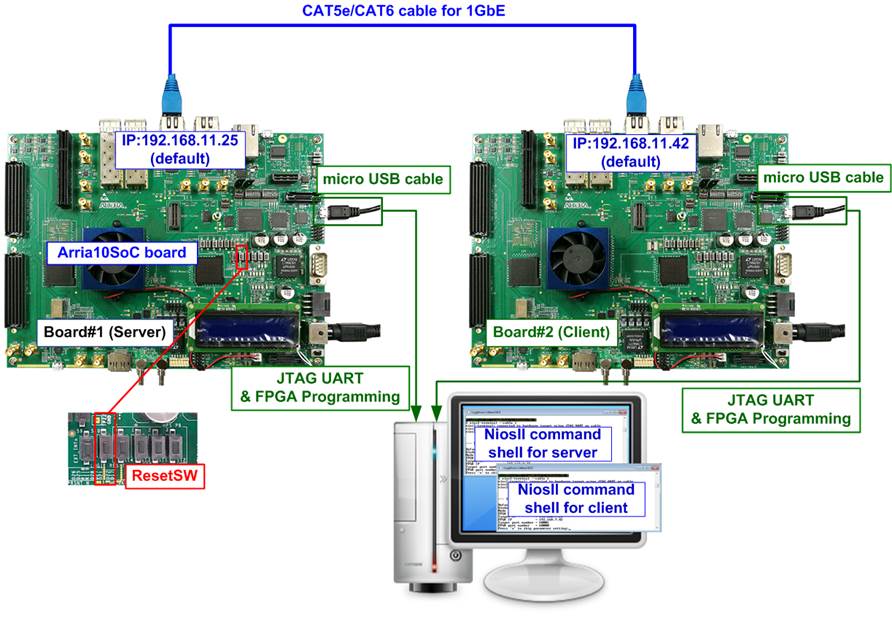
Figure 2‑1 TOE1G-IP/UDP1G-IP with CPU demo (FPGA<->FPGA)
The step to setup test environment by using two FPGAs is described in more details as follows.
Follow step 1) – 5) of topic 1 (Test environment setup when using FPGA and PC) to prepare FPGA board for running the demo. After two FPGA boards have been configured completely, NiosII command shell displays the menu to select client mode or server mode. The step after FPGA configuration is described as follows.
1) Open NiosII command shell.
a. Type “nios2-terminal -- cable 1” to open NiosII terminal of FPGA board#1 (USB-1 port)
b. Type “nios2-terminal -- cable 2” to open NiosII terminal of FPGA board#2 (USB-2 port)
c. Set ‘1’ on NiosII command shell of FPGA board#1 for running server mode.
Set ‘0’ on NiosII command shell of FPGA board#2 for running client mode.
d. Default parameters for server or client are displayed on the console, as shown in Figure 2‑3.
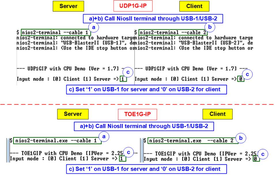
Figure 2‑2 Input mode

Figure 2‑3 Default parameter
2) Input ‘x’ to use default parameters or other keys to change parameters. The parameters of server mode must be set before client mode.
When running TOE1G-IP,
a. Set parameters on Server console.
b. Set parameters on Client console to start IP initialization by transferring ARP packet.
c. After finishing initialization process. “IP initialization complete” and main menu are displayed on server console and client console.
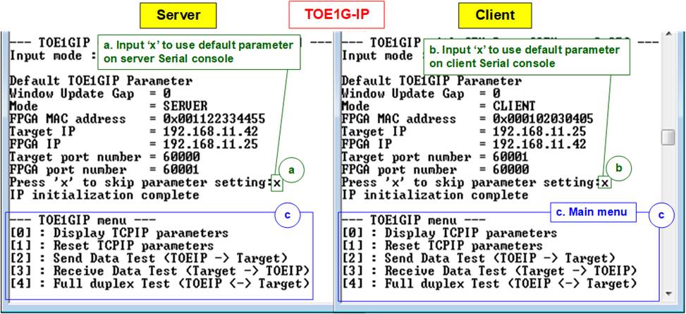
Figure 2‑4 Main menu of TOE1G-IP
When running UDP1G-IP,
a. For server mode, if user does not change default parameters, input ‘x’ to skip parameter setting.
b. For client mode, user must change target port number (Target->FPGA) to use same value as target port number (FPGA->Target).
c. After finishing initialization process. “IP initialization complete” and main menu are displayed on server console and client console.
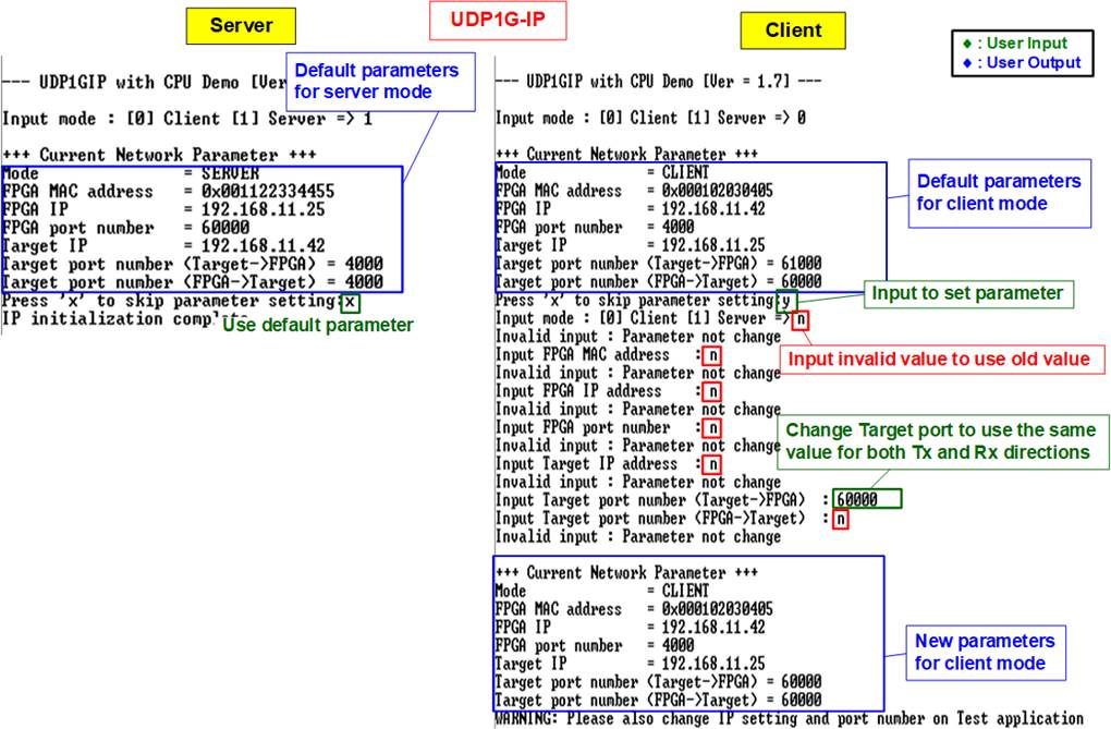
Figure 2‑5 Main menu of UDP1G-IP
3 Revision History
|
Revision |
Date |
Description |
|
1.0 |
3-Mar-17 |
Initial version release |
|
2.0 |
11-Feb-21 |
Setup TOE1G-IP and UDP1G-IP and add Arria10 GX Board |