FPGA Setup for TOE/UDP1G IP with CPU Demo
1 Test environment setup when using FPGA and PC
2 Test environment setup when using two FPGAs
This document describes how to setup FPGA board and prepare the test environment for running TOE1G-IP or UDP1G-IP demo. The user can setup two test environments for transferring TCP data or UDP data via 1Gb Ethernet connection by using TOE1G-IP or UDP1G-IP, as shown in Figure 1‑1.
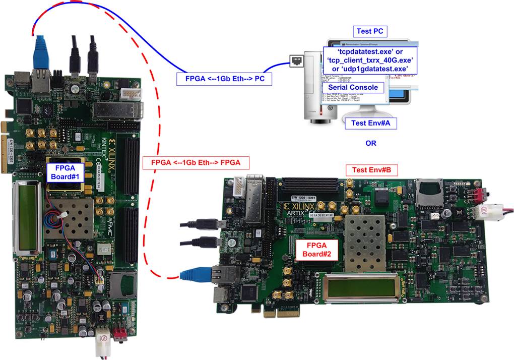
Figure 1‑1 Two test environments for running the demo
First uses one FPGA board and Test PC with 1Gb Ethernet card for transferring the data. Test PC runs test application, i.e., tcpdatatest (half-duplex test for TOE1G-IP), tcp_client_txrx_40G for (full-duplex test for TOE1G-IP) or udp1gdatatest (test application for UDP1G-IP). Also, Serial console is run on Test PC to be user interface console.
Second uses two FPGA boards which may be different board or the same board. Both boards run TOE1G-IP or UDP1G-IP demo with assigning the different initialization mode (Client for Server) for transferring data.
1 Test environment setup when using FPGA and PC
Before running the test, please prepare following test environment.
- FPGA development boards: ZC706/KC705/AC701 board
- PC with 1 Gigabit Ethernet or connecting with 1 Gigabit Ethernet card
- 1Gb Ethernet connection: Cat5e or Cat6 cable for between FPGA and PC/FPGA
Note: When using ZC706, SFP+ to RJ45 adapter for connecting to SFP+ connector on ZC706 board must be used.
- micro USB cable for programming FPGA, connecting between FPGA board and PC
- mini USB cable for Serial console, connecting between FPGA board and PC
- Test application provided by Design Gateway for running on Test PC:
TOE1G-IP: “tcpdatatest.exe” and “tcp_client_txrx_40G.exe”
UDP1G-IP: “udp1gdatatest.exe”
- Serial console software such as TeraTerm installed on PC. The setting on the console is Baud rate=115,200, Data=8-bit, Non-parity and Stop=1.
- Vivado tool for programming FPGA, installed on PC
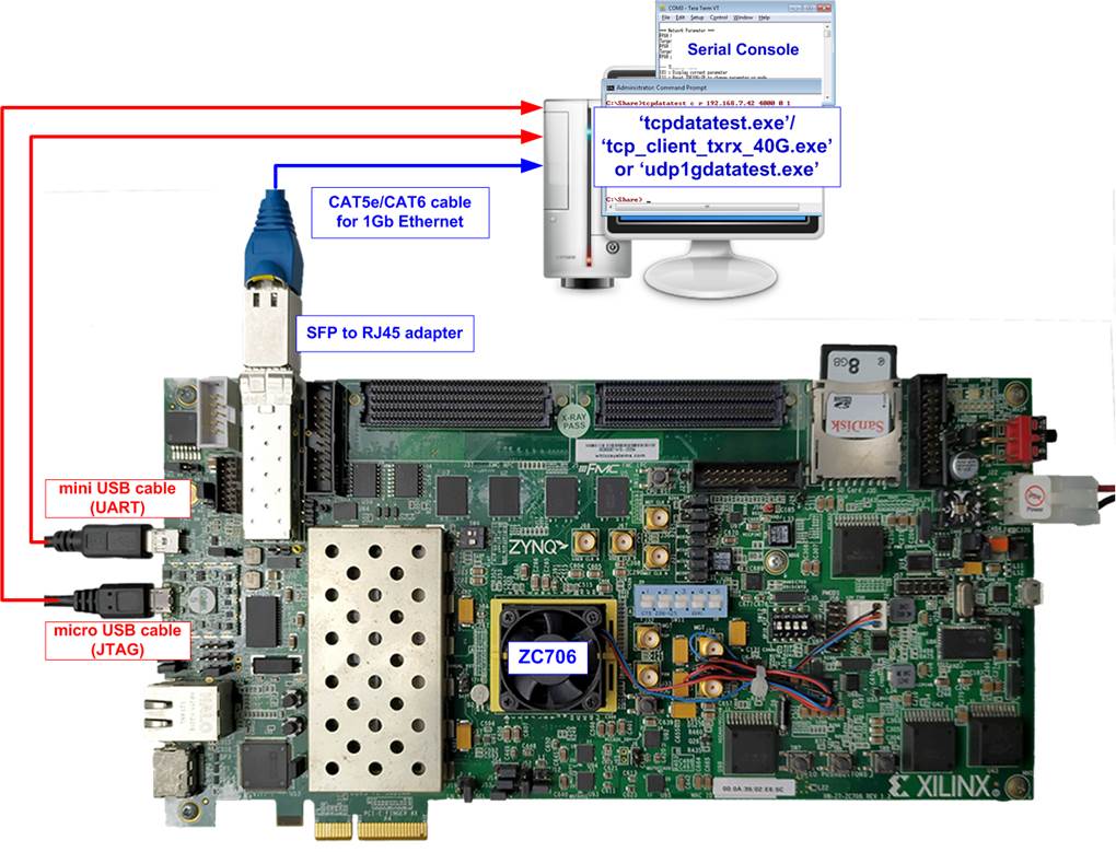
Figure 1‑1 TOE1G-IP/UDP1G-IP with CPU demo (FPGA <-> PC) on ZC706
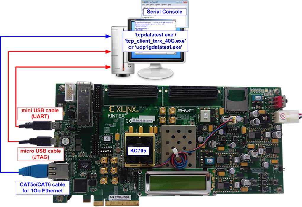
Figure 1‑2 TOE1G-IP/ UDP1G-IP with CPU demo (FPGA <-> PC) on KC705
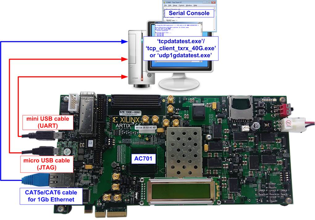
Figure 1‑3 TOE1G-IP/UDP1G-IP with CPU demo environment setup on AC701
The step to setup test environment by using FPGA and PC is described in more details as follows.
2) Connect micro USB cable and mini USB cable from FPGA board to PC for JTAG programming and USB UART (Serial Console).
3) Connect power supply to FPGA development board.
4) For ZC706, connect SFP to RJ45 adapter into SFP+ connector on ZC706 board.
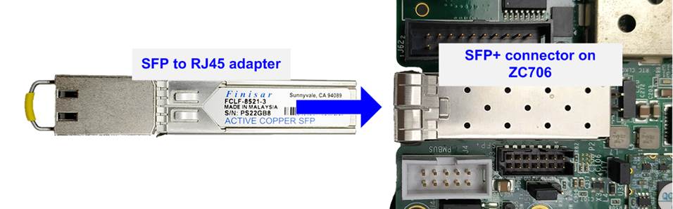
Figure 1‑4 Connect SFP to RJ45 adapter to ZC706
5) Connect CAT5e or CAT6 cable between RJ45 on FPGA board to PC
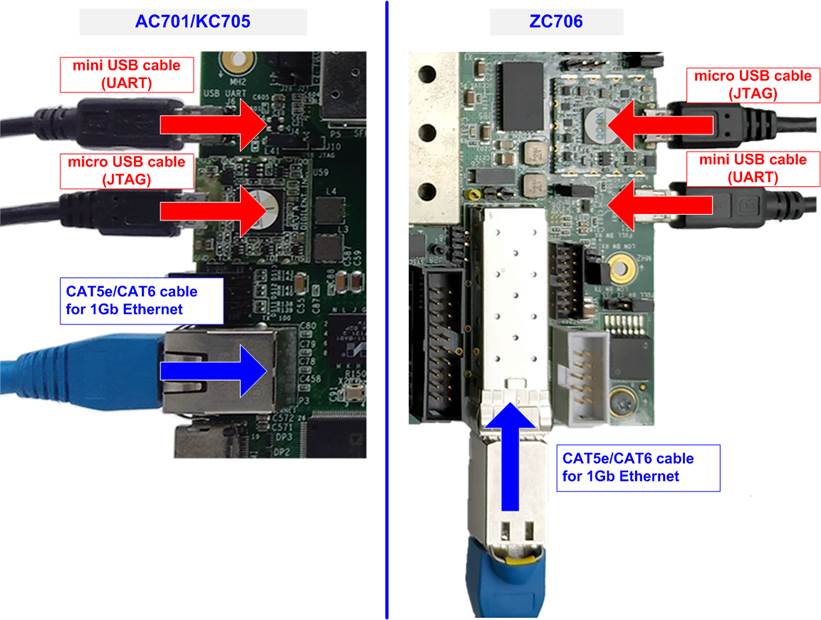
Figure 1‑5 Connect cable between FPGA and PC
6) Power on FPGA board.
7) Open Serial console to connect to FPGA board. Serial setting is Baud rate = 115,200, Data=8-bit, Non-parity, and Stop = 1.
8) Download and program configuration file and firmware to FPGA board.
a) For ZC706 board, open Vivado TCL shell and change current directory to download folder which includes demo configuration file. Type “xxx1gcputest_zc706.bat”, as shown in Figure 1‑6 .
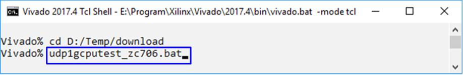
Figure 1‑6 Example command script for download to ZC706 by Vivado tool
b) For AC701/KC705 board, configure FPGA by using Vivado, as shown in Figure 1‑7.
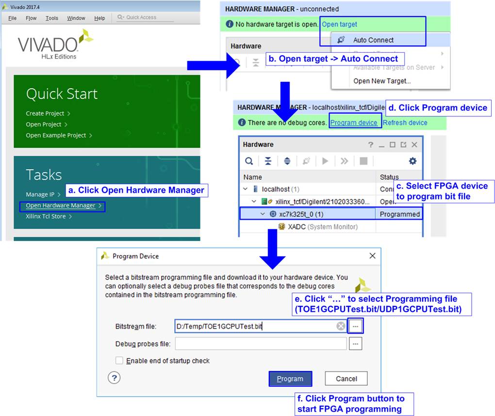
Figure 1‑7 Program FPGA by Vivado for AC701/KC705
9) On serial console, welcome message is displayed.
a. Input ‘0’ to initialize TOE1G-IP/UDP1G-IP in client mode (ask PC MAC address by sending ARP request).
b. Default parameter in client mode is displayed on the console.
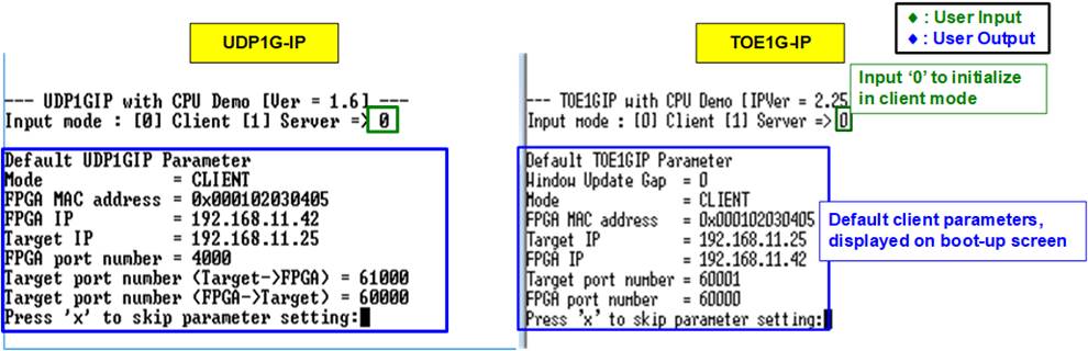
Figure 1‑8 Message after system boot-up
c. User enters ‘x’ to skip parameter setting for using default parameters to begin system initialization, as shown in Figure 1‑9. If user enters other keys, the menu for changing parameter is displayed, similar to “Reset TCPIP/UDPIP parameters” menu. The example when running the main menu is described in “dg_toe1gip_cpu_instruction” or “dg_udp1gip_cpu_instruction document.
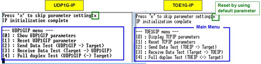
Figure 1‑9 Initialization complete
Note: Transfer performance in the demo depends on Test PC resource in Test platform.
2 Test environment setup when using two FPGAs
Before running the test, please prepare following test environment.
- Two FPGA development boards which are the same board or the different board, ZC706/KC705/AC701
- Cat5e or Cat6 cable for 1 Gb Ethernet connection between two FPGA boards (Ethernet connection between two FPGA boards could be connected directly or connected through other network devices such as Ethernet switch)
Note: When using ZC706, insert SFP to RJ45 adapter to SFP+ connector on FPGA board.
- Connect micro USB cable and mini USB cable for programming FPGA and Serial console between each FPGA board and PC (two sets are used for two FPGA boards)
- Serial console software such as TeraTerm, installed on PC. The setting on the console is Baudrate=115,200, Data=8-bit, Non-parity, and Stop=1.
- Vivado tool for programming FPGA, installed on PC
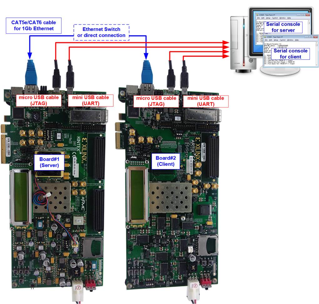
Figure 2‑1 TOE1G-IP/UDP1G-IP with CPU demo (FPGA<->FPGA)
The step to setup test environment by using two FPGAs is described in more details as follows.
Follow step 1) – 8) of topic 1 (Test environment setup when using FPGA and PC) to prepare FPGA board for running the demo. After two FPGA boards have been configured completely, Serial console displays the menu to select client mode or server mode. The step after FPGA configuration is described as follows.
1) Open Serial console for board#1 and board#2 which are initialized as Server and Client respectively.
a. Set ‘1’ on Serial console of FPGA board#1 for running server mode.
b. Set ‘0’ on Serial console of FPGA board#2 for running client mode.
c. Default parameters for server or client are displayed on the console, as shown in Figure 2‑2.
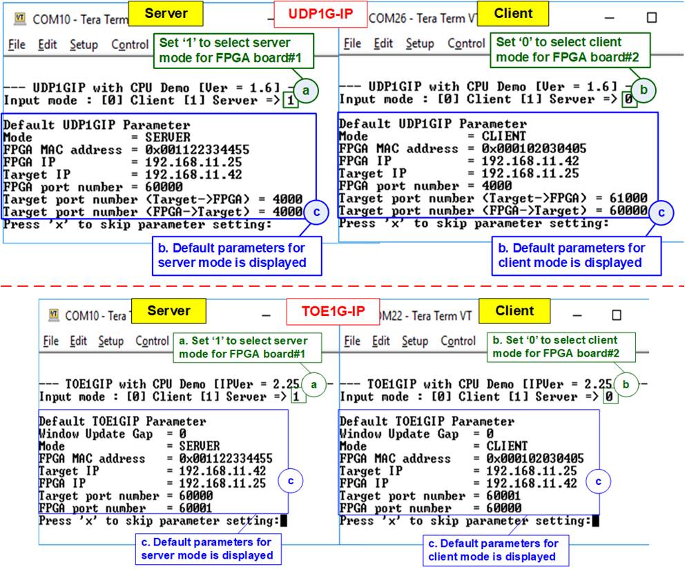
Figure 2‑2 Input mode
2) Input ‘x’ to use default parameters or other keys to change parameters. The parameters of server mode must be set before client mode.
When running TOE1G-IP,
a. Set parameters on server Serial console.
b. Set parameters on client Serial console to start IP initialization by transferring ARP packet.
c. After finishing initialization process. “IP initialization complete” and main menu are displayed on server console and client console.
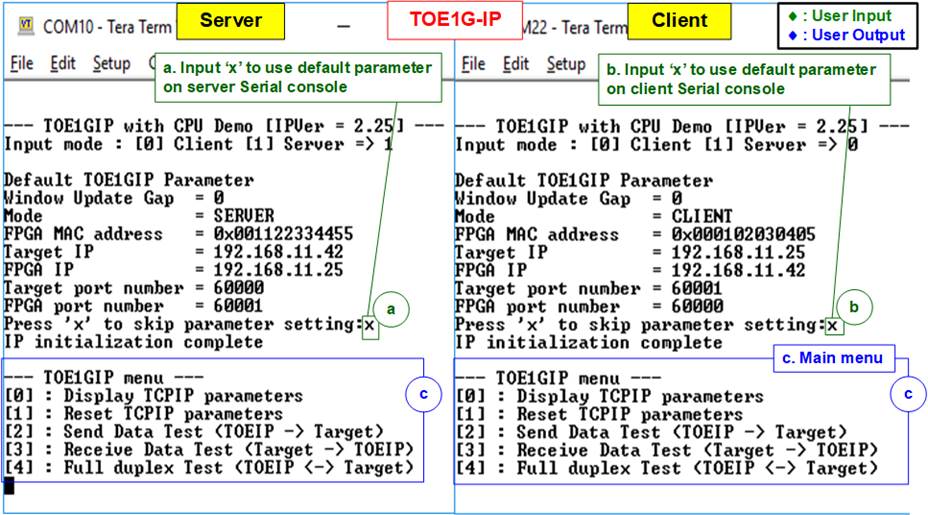
Figure 2‑3 Main menu of TOE1G-IP
When running UDP1G-IP,
a. For server mode, if user does not change default parameters, input ‘x’ to skip parameter setting.
b. For client mode, user must change target port number (Target->FPGA) to use same value as target port number (FPGA->Target).
c. After finishing initialization process. “IP initialization complete” and main menu are displayed on server console and client console.
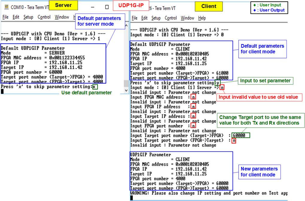
Figure 2‑4 Main menu of UDP1G-IP
3 Revision History
|
Revision |
Date |
Description |
|
1.0 |
2-Nov-18 |
Initial version release |
|
2.0 |
31-Jul-20 |
Remove test result on the console |
|
3.0 |
10-Nov-20 |
TOE1G-IP and UDP1G-IP |