TOE25G-IP 4 Session Demo Instruction
Rev1.0 5-Jul-23
3 Test result when using FPGA and TestPC
3.3.3 Mixed Send - Receive Test
4 Test result when using two FPGAs
1 Overview
This document shows the example to run multi-session TOE25G-IP demo with 4 instances by using two test environments. First is run by using one FPGA board transferring TCP payload data with TestPC which runs test applications for transferring data via 25Gb Ethernet. Test performance on the first environment depends on the resource of TestPC. Second is run by using two FPGA boards for transferring 25G Ethernet data to each other.
In the document, topic 2 shows the example to set up 25G Ethernet card on TestPC to get the good performance for transferring data via 25Gb Ethernet when running the test by using the first test environment, FPGA and Test PC. Topic 3 shows the example console and test result when running under the first test environment. Finally, topic 4 shows the example console when running the second test environment, FPGA and FPGA. More details of each topic are described as follows.
2 PC Setup
Before running demo, please check the network setting on PC. The example for setting 25G Ethernet card is described as follows.
2.1 IP Setting
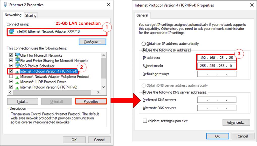
Figure 2‑1 Setting IP address for PC
1) Open Local Area Connection Properties of 25-Gb connection, as shown in the left window of Figure 2‑1.
2) Select “TCP/IPv4” and then click Properties.
3) Set IP address = 192.168.25.25 and Subnet mask = 255.255.255.0, as shown in the right window of Figure 2‑1.
2.2 Speed and Frame Setting
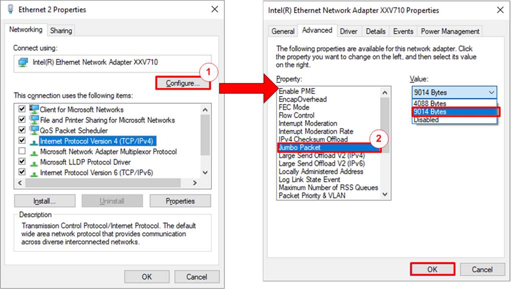
Figure 2‑2 Set frame size = Jumbo frame
1) On Local Area Connection Properties window, click “Configure” as shown in Figure 2‑2.
2) On Advanced Tab, select “Jumbo Packet”. Set Value to “9014 Bytes” for Jumbo Frame support or set value to “Disabled” for non-Jumbo Frame support, as shown in the right window of Figure 2‑2.
3) Select “Speed & Duplex”. Set value to “25 Gbps Full Duplex” for running 25-Gigabit transfer test, as shown in Figure 2‑3.
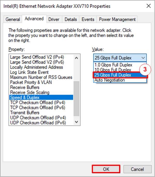
Figure 2‑3 Set link speed = 25 Gbps
4) Select “Interrupt Moderation” and set value to “Disabled”, as shown in Figure 2‑4.
5) Click “OK” button to save and exit all setting windows.
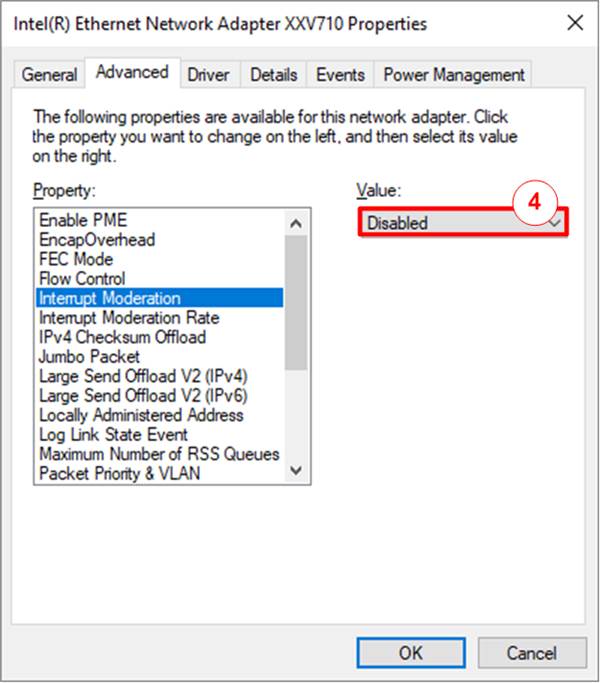
Figure 2‑4 Interrupt Moderation
2.3 Power Option Setting
1) Open Control Panel and select Power Options as shown in the left window of Figure 2‑5.
2) Change setting to High Performance as shown in the right window of Figure 2‑5.

Figure 2‑5 Power options
3 Test result when using FPGA and TestPC
3.1 Display TCPIP parameters
Select ‘0’ to check current parameter in the demo. There are two groups of the parameters, i.e., Common parameters which are shared for all session and Session parameters which are set to each session individually. Typically, it is recommended to set initialization mode = “Client mode” for running FPGA and Test PC. Fixed-MAC mode can be run if the user knows the MAC address of Test PC.
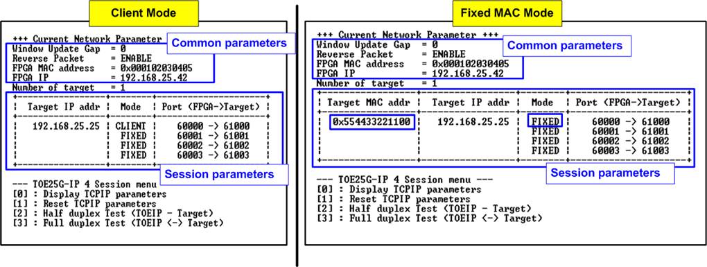
Figure 3‑1 Display current parameter result
- Common parameter: There are four Common parameters.
1) Window Update Gap: Set threshold value to transmit Window update packet. Valid value is 0x00 – 0x3F (0-63). The unit size of threshold value is 1 Kbyte. Default value is 0 (Disable Window update feature).
2) Reverse Packet: This flag is enabled to allow the IP sending the retransmitted packet when IP waits Windows update packet returned from the target for long time. Default value is ENABLE.
3) FPGA MAC address: 48-bit hex value to be MAC address of FPGA. Default value is 0x000102030405.
4) FPGA IP: IP address of FPGA. Default value is 192.168.25.42.
Note: This value is used to be Server IP address parameter for test application on PC.
Before displaying Session parameters, the number of target devices set by user is displayed. The example shows one target applied, so the same Target MAC address and Target IP address are set to all sessions.
While the initialization mode of the first session of each target device can be selected, the rest sessions of the same target device are automatically set to be Fixed MAC mode. The details of Session parameter are described as below.
- Session parameter: There are three or four Session parameters, depending on mode.
1) Target MAC address (displayed when running Fixed MAC mode only): 48-bit hex value to be MAC address of the target device. Default value is 0x554433221100.
2) Target IP address: IP address of the target device (25 Gb Ethernet on PC). Default value is 192.168.25.25.
3) Initialization mode: TOE25G-IP initialization mode which can be selected to ‘0’ (Server), ‘1’ (Client), or ‘2’ (Fixed MAC). To run with PC, please input ‘0’ to initialize the IP in Client mode.
4) Port number (FPGA->Target): Port number of FPGA is the left-hand side value and port number of target device is the right-hand side value. This parameter is assigned to each session individually. Default parameters of 4 sessions are 60000 - 60003 and 61000 - 61003, respectively.
Note: Port number of FPGA is used to be server port for test application on PC.
To change parameters, user can set by using menu [1].
3.2 Reset TCPIP parameters
Select ‘1’ to reset the IP and change IP parameters.
This menu is used to change IP parameters or send reset to TOE25G-IPs. After selecting this menu, the current parameters are displayed on the console. User enters ‘x’ to use the same parameters while other keys are entered to change parameters. After the parameters are fixed, all TOE25G-IPs are reset and start the initialization process.
The description of each parameter is shown in topic 3.1 (Display TCPIP parameter) and the range of each parameter is described as follows.
1) Mode: Input ‘0’, ‘1’, or ‘2’ to initialize the IP as Client mode, Server mode, or Fixed MAC mode, respectively.
Note: When TestPC and FPGA are connected in different network which cannot communicate by ARP process, it needs to run TOE25G-IP in Fixed MAC mode to set MAC address manually via the console instead of using ARP process.
2) Reverse Packet: Set ‘0’ to disable or ‘1’ to enable this feature.
3) Window Update Gap: Set threshold value to transmit Window update packet. Valid value is 0x00 – 0x3F (0-63). The unit size of threshold value is 1 Kbyte. Default value is 0 (Disable Window update feature).
4) FPGA MAC address: Input 12 digits of hex value. Add “0x” as a prefix to input as hex value.
5) FPGA IP address: A set of four decimal digits is separated by “.”. The valid range of each decimal digit is 0-255.
6) Number of target: The total number of target devices that connect with multiple TOE25G-IPs. Valid range is 1-4 (Number of TOE25G-IPs in this demo).
After that the user starts setting the parameters of each session.
1) Target MAC address (displayed when running Fixed MAC mode only): Input 12 digits of hex value. Add “0x” as a prefix to input as hex value.
2) Target IP address: A set of four decimal digits, similar to FPGA IP address. This value is IP address of Test PC.
Note: Target MAC address and Target IP address for different target devices (when number of targets is more than one) must be set to different value.
3) Number of sessions: The total number of TCP session in this target device. Valid range depends on the number of targets. For one target device system, the number of sessions can be set to 1 - 4.
4) FPGA port number of the current session: Valid range is 0-65535.
5) Target port number of the current session: Valid range is 0-65535.
Note: Port number of different session in the same target device must be assigned by different value.
After finishing parameter assignment, the assigned parameters are displayed on the console. Next, the reset signal is sent to all IPs to initialize the IPs by using new parameters. Finally, “IP initialization complete” is shown after the IPs complete initialization process, as shown in Figure 3‑2.

Figure 3‑2 Change IP parameter in Client and Fixed-MAC mode result
3.3 Half-duplex Test
To transfer data in single direction, select ‘2’ to run half-duplex test on FPGA and run “tcpdatatest.exe” on PC to send or receive data. The half-duplex test allows user to disable or enable to send/receive data of each TOE25G-IP individually. Also, the test parameters of each TOE25G-IP are assigned individually. User sets three values for each session, i.e., ‘0’-No operation, ‘1’-Send test, and ‘2’-Receive test. The details when running by Send test, Receive test, and Mixed test (Send and Receive) are shown as below.
3.3.1 Send Test
When Send test is selected, PC must run “tcpdatatest” to receive the data by using the recommend parameters for that session. The sequence to run Send test is shown as follows.
1) On FPGA console, input test parameters of each session.
a) Input test mode: ‘0’-Disable and skip to assign the next session, ‘1’-Send test.
b) Input transfer size: Unit of transfer size is byte. Valid value is 0x10 - 0xF_FFFF_FFF0. The input must be aligned to 16. The input is decimal unit when input only digit number. User adds “0x” to be a prefix for hexadecimal unit.
c) Input packet: Unit of packet size is byte. Valid value is 16 – 8960. The input must be aligned to 16. The input is decimal unit when input only digit number. User adds “0x” to be a prefix for hexadecimal unit.
Note: If packet size is more than 1456, the packet output from TOE25G-IP is considered as jumbo frame. In this case, Test PC must support jumbo frame.
d) Input operation mode: Input ‘1’ to transfer as Server mode.
The input assignment is repeated until all sessions are assigned.
2) If all inputs are valid, the recommended parameters to run test application on PC are displayed. Next, the parameters of the active session are displayed. “Wait connection” is displayed to wait until the application is run on PC.
3) On PC, open Command prompt window for running the recommended commands from FPGA console. Input test parameters following the recommended value. There are six parameters for “tcpdatatest” for running to receive data.
>> tcpdatatest <mode> <dir> <server IP> <server port> <bytelen> <pattern>
a) Mode: Input ‘c’ to run Test PC as a Client.
b) Dir: Input ‘r’ to run Test PC for receiving and verifying test data from FPGA
c) Server IP: Input the same value as IP address of FPGA
d) Server port: Input the same value as port number of FPGA on the selected session
e) Bytelen: Input the same value as “Input transfer size” of step 1b) on the selected session
f) Pattern: Input ‘1’ to verify data from FPGA or ‘0’ to not verify data
4) After running the test application, the port is created. Current amount of transferred data is displayed on the console (transmitted data) and Command prompt (received data) every second. “Closed” might be displayed on the console after all data in the session are completely transferred.
5) “Half-duplex test complete” is displayed after all connections are closed. Finally, total amount of transferred data and performance of all active sessions are displayed on the console (Transmit performance) and Command prompt (Receive performance). Also, “Total performance” is displayed on console if multiple sessions are run.
Note: Total performance may be less than the sum of each session performance because time usage is measured from the first session is started to the final session is finished.
Figure 3‑3 shows the example of two-session Send test when using normal packet size with enabling data verification on test application. The left window is FPGA console operating as Server and the right windows are two Command prompt windows on PC operating as Client.

Figure 3‑3 Two-session Send test for by using normal packet size with data verification
Figure 3‑4 shows the example of four-session Send test when using normal packet size with enabling data verification on test application. Comparing with two-session test shown in Figure 3‑3, the performance of each session is reduced while the performance of total session is slightly increased.
When changing the packet size to be jumbo-frame size (8960 byte), the performance is increased, as shown in Figure 3‑5.
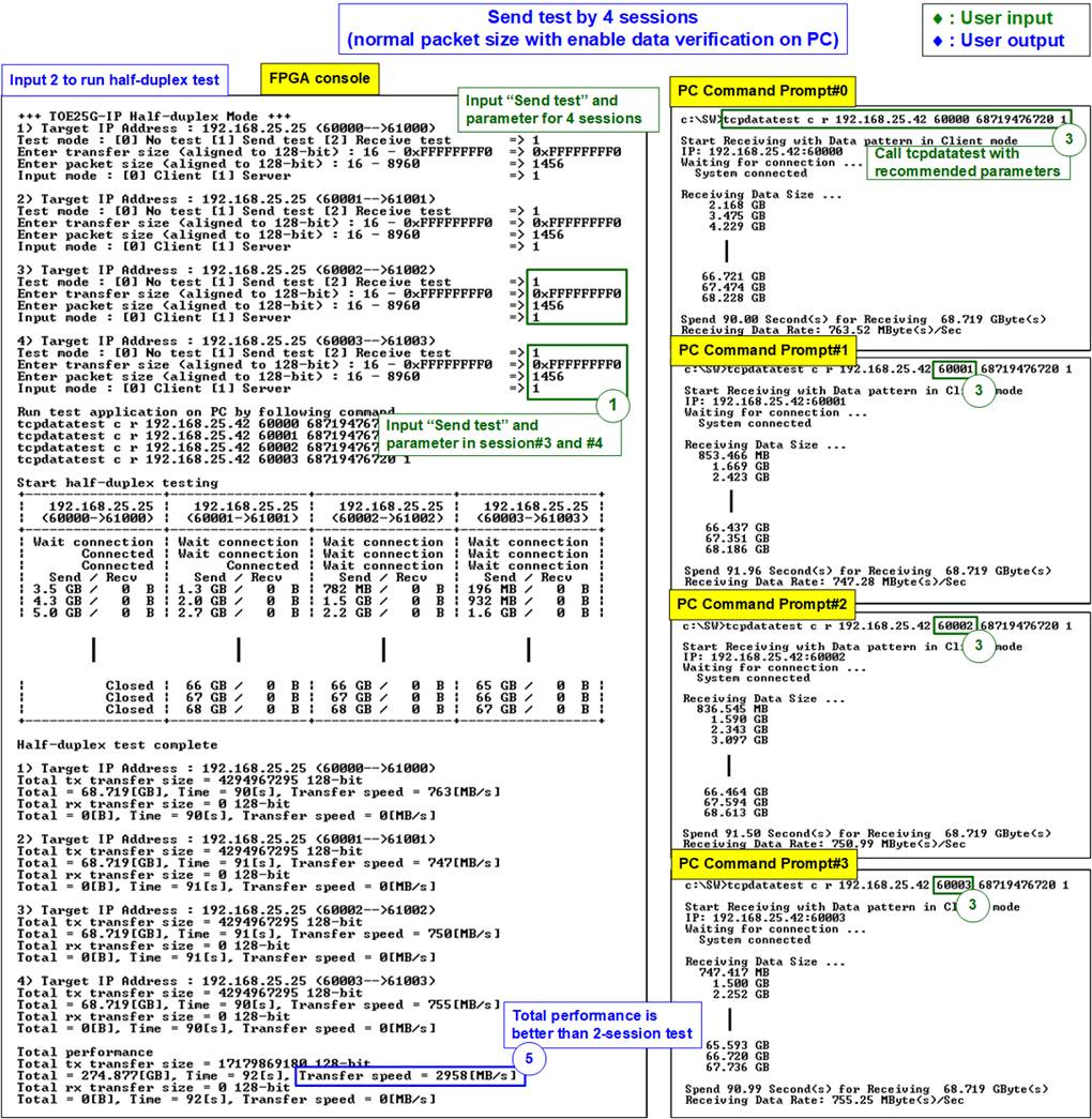
Figure 3‑4 Four-session Send test by using normal packet size with data verification
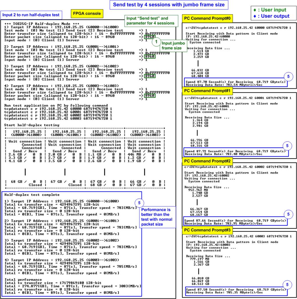
Figure 3‑5 Four-session Send test when using jumbo frame size with data verification
In the test environment, the line rate of the 25Gb Ethernet speed is 3125 MB/s while the four-session test with maximum frame size (8960 byte) shows 3083 MB/s. Total performance is almost equal to the line rate of 25Gb Ethernet speed.
Note: The performance by FPGA and PC may be not stable. It depends on how OS handling the application during running the test.
If the input is invalid, “Out-of-range input” or “Invalid input” is displayed. After that, the operation is cancelled, as shown in Figure 3‑6 - Figure 3‑7.

Figure 3‑6 Error from out-of-range input
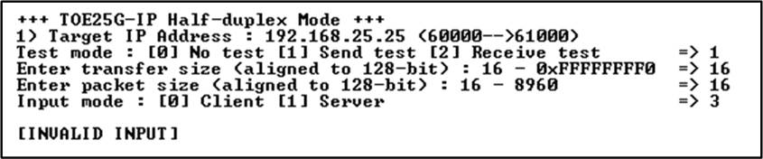
Figure 3‑7 Error from invalid input
3.3.2 Receive Test
When Receive test is selected, PC must run “tcpdatatest” to send the data by using the recommend parameters for that session. The sequence to run Receive test is shown as follows.
1) On FPGA console, input test parameters of each session.
a) Input test mode: ‘0’-Disable and skip to assign the next session, ‘2’-Receive test.
b) Input transfer size: Unit of transfer size is byte. Valid value is 0x10 - 0xF_FFFF_FFF0. The input must be aligned to 16. The input is decimal unit when input only digit number. User adds “0x” to be a prefix for hexadecimal unit.
c) Input data verification mode: ‘0’-disable data verification, ‘1’-enable data verification.
d) Input operation mode: Input ‘1’ to transfer as Server mode.
The input assignment is repeated until all sessions are assigned.
2) If all inputs are valid, the recommended parameters to run test application on PC are displayed. Next, the parameters of the active session are displayed. “Wait connection” is displayed to wait until the application is run on PC.
3) On PC, open Command prompt window for running the recommended command from FPGA console. Input test parameters following the recommended value. There are six parameters for “tcpdatatest”.
>> tcpdatatest <mode> <dir> <server IP> <server port> <bytelen> <pattern>
a) Mode: Input ‘c’ to run Test PC as a Client.
b) Dir: Input ‘t’ to run Test PC for sending test data to FPGA
c) Server IP: Input the same value as IP address of FPGA
d) Server port: Input the same value as port number of FPGA on the selected session
e) Bytelen: Input the same value as “Input transfer size” of step 1b) on the selected session
f) Pattern: Input the same value as “Input data verification mode” of step 1c) on the selected session. ‘0’-Send dummy data, ‘1’-Send incremental data.
4) After running the test application, the port is created. Current amount of transferred data is displayed on the console (received data) and Command prompt (transmitted data) every second. “Closed” might be displayed on the console after all data in the session is completely transferred.
6) “Half-duplex test complete” is displayed after all connection are closed. Finally, total amount of transferred data and performance of all active sessions are displayed on the console (Receive performance) and Command prompt (Transmit performance). Also, “Total performance” is displayed on console if multiple sessions are run.
Note: Total performance may be less than the sum of all session performance because time usage is measured from the first session is started to the final session is finished.
Figure 3‑8 shows the example of two-session Receive test when data verification mode on FPGA is enabled and incremental data is sent by PC. The left window is FPGA console operating as Server and the right window is two Command prompt windows on PC operating as Client.

Figure 3‑8 Two-session Receive test with data verification
Figure 3‑9 shows the example of four-session Receive test when data verification mode on FPGA is enabled and incremental data is sent by PC. Comparing to Figure 3‑8, the performance in the test environment is better when increasing the number of sessions.
Figure 3‑10 shows the example performance of four-session Receive test when data verification mode on FPGA is disabled and dummy data is sent by PC. Comparing to Figure 3‑9, the result shows the best performance because CPU uses less resource to handle the task.

Figure 3‑9 Four-session Receive test with data verification
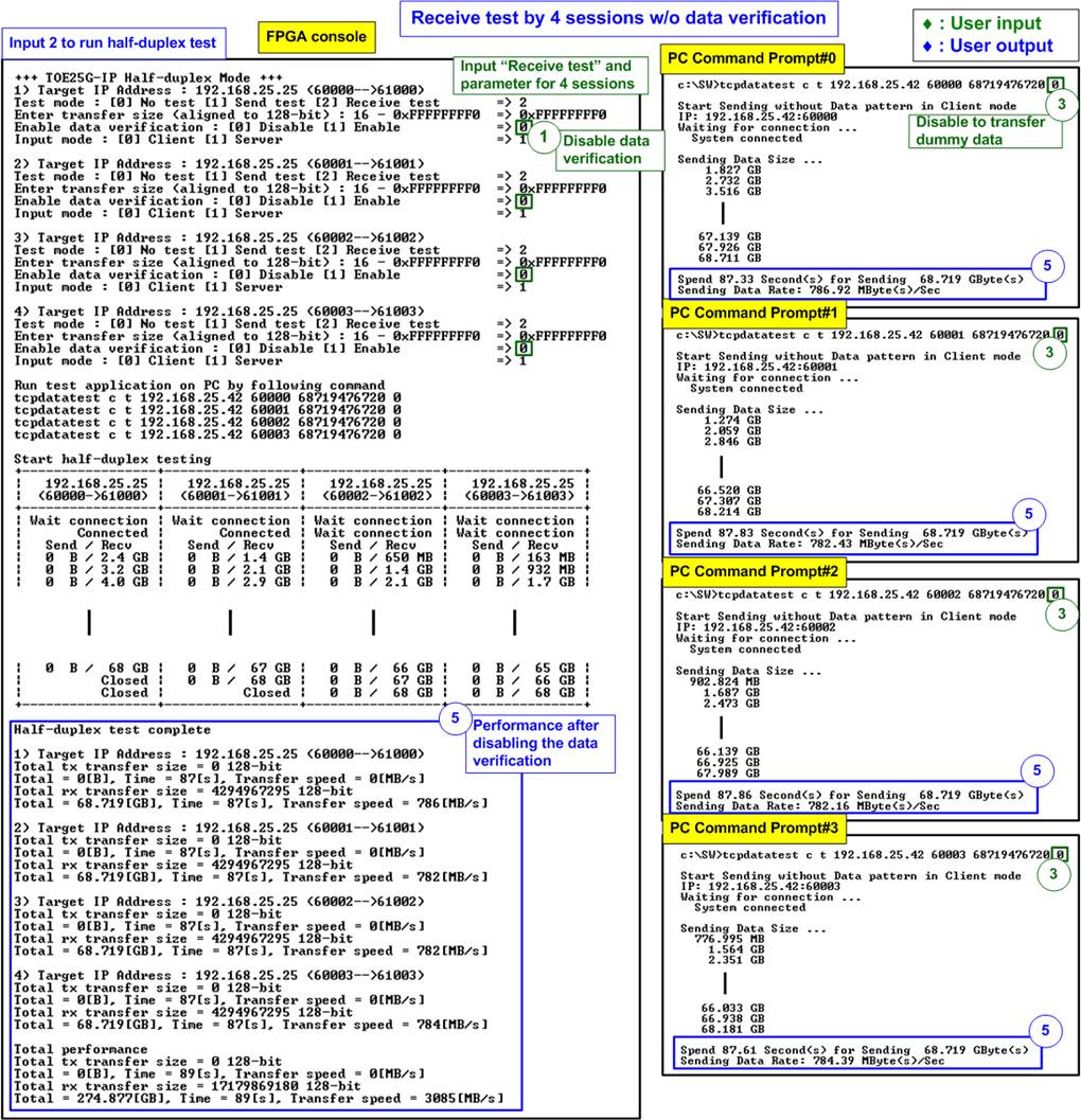
Figure 3‑10 Four-session Receive test without data verification
In Figure 3‑10, the total transfer speed is 3085 MB/s which is almost equal to the line rate of the 25Gb Ethernet speed (3125 MB/s).
3.3.3 Mixed Send - Receive Test
When user sets Send test to some sessions and Receive test to remaining sessions, PC runs “tcpdatatest” on many Command prompts to receive data and send data. The sequence to run Mixed Send - Receive test is shown as follows.
1) On FPGA console, input test parameters of each session.
b) Input transfer size: Unit of transfer size is byte. Valid value is 0x10 - 0xF_FFFF_FFF0. The input must be aligned to 16. The input is decimal unit when input only digit number. User adds “0x” to be a prefix for hexadecimal unit.
c) Input packet size (Send test only): Unit of packet size is byte. Valid value is 16 – 8960. The input must be aligned to 16. The input is decimal unit when input only digit number. User adds “0x” to be a prefix for hexadecimal unit.
d) Input data verification mode (Receive test only): ‘0’-disable data verification, ‘1’-enable data verification.
e) Input operation mode: Input ‘1’ to transfer as Server mode.
The input assignment is repeated until all sessions are assigned.
2) If all inputs are valid, the recommended parameters to run test application on PC are displayed. Next, the parameters of the active session are displayed. “Wait connection” is displayed to wait until the application is run on PC.
3) On PC, open Command prompt window for running the recommended command from FPGA console. Input test parameters following the recommended value. There are six parameters for “tcpdatatest”.
>> tcpdatatest <mode> <dir> <server IP> <server port> <bytelen> <pattern>
a) Mode: Input ‘c’ to run Test PC as a Client.
b) Dir: Input ‘r’ to run Test PC for receiving and verifying test data or
‘t’ to run Test PC for transmitting test data.
c) Server IP: Input the same value as IP address of FPGA
d) Server port: Input the same value as port number of FPGA on the selected session
e) Bytelen: Input the same value as “Input transfer size” of step 1b) on the selected session
f) Pattern: To receive data, input ‘1’ to verify data from FPGA or ‘0’ to not verify data. To send data, input the same value as “Input data verification mode” of step 1d) on the selected session.
4) After running the test application, the port is created. Current amount of transferred data for both transmit side and receive side is displayed on the console and Command prompt every second. “Closed” might be displayed on the console after all data in the session is completely transferred.
5) “Half-duplex test complete” is displayed after all connection are closed. Finally, total amount of transferred data and performance of all active session are displayed on the console and Command prompt. Also, “Total performance” is displayed on console if multiple sessions are run.
Figure 3‑11 shows the example of running Send test for one session and Receive test for one session. The result without PC console is displayed.
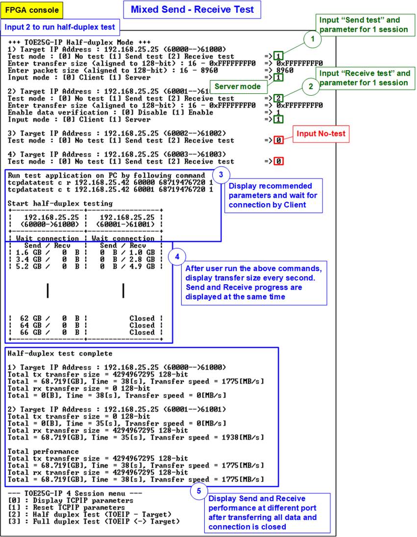
Figure 3‑11 One-session Send test and one-session Receive test
3.4 Full duplex Test
Select ‘3’ to run full duplex test to transfer data between FPGA and PC in both directions. After that, it will enter the full-duplex mode and test parameters of each session can be individually assigned. User can enable or disable each session by Test mode parameters. User inputs test parameters of the active session on FPGA console and then opens command prompts on TestPC to run “tcp_client_txrx_single” application. Multiple applications are run to support multi-session test. The sequence to run the test is shown as below.
1) On FPGA console, input test parameters of each session.
a) Input test mode: ‘0’-Disable and skip to assign the next session, ‘1’-Full duplex test.
b) Input transfer size: Unit of transfer size is byte. Valid value is 0x10 - 0xF_FFFF_FFF0. The input must be aligned to 16. The input is decimal unit when input only digit number. User adds “0x” to be a prefix for hexadecimal unit. This value must be equal to total transfer size, set on test application.
c) Input packet size: Unit of packet size is byte. Valid value is 16 – 8960. The input must be aligned to 16. The input is decimal unit when input only digit number. User adds “0x” to be a prefix for hexadecimal unit.
f) Input data verification mode: ‘0’-disable data verification, ‘1’-enable data verification.
d) Input operation mode: Input ‘1’ to transfer as Server mode.
The input assignment is repeated until all sessions are assigned.
2) If all inputs are valid, the recommended parameters to run test application on PC are displayed. Next, the parameters of the active session are displayed. “Wait connection” is displayed to wait until the application is run on PC.
3) On PC, open Command prompt window for running the recommended command from FPGA console. Input test parameters following the recommended value. There are four parameters for “tcp_client_txrx_single”.
>> tcp_client_txrx_single <server IP> <server port> <bytelen> <pattern>
a) Server IP: Input the same value as IP address of FPGA
b) Server port: Input the same value as port number of FPGA on the selected session
c) ByteLen: Total transfer size in byte unit. Input the same value as “Input transfer size” of step 1b) on the selected session.
d) Pattern: ‘0’ - Send dummy data and disable data verification. ‘1’ - Send incremental data and enable data verification. Input the same value as “Input data verification mode” of step 1d) on the selected session.
4) After running the test applications, the port is created. Current amount of transferred data in both directions is displayed on the console and Command prompt every second. “Closed” might be displayed on the console after all data in the session is completely transferred.
5) “Full-duplex test complete” is displayed after all connection are closed. Finally, total amount of transferred data and performance of all active session in both transferred directions are displayed on the console and Command prompt. Also, “Total performance” is displayed on console if multiple sessions are run.
Figure 3‑12 shows the example of two-session full-duplex test when data verification mode on FPGA is enabled. Therefore, incremental data is sent by PC and received data is verified by PC. Jumbo-frame size is sent by FPGA to PC. The left window is FPGA console operating as Server and the right windows are two Command prompt windows on PC operating as Client.
In comparison with Figure 3‑3 and Figure 3‑8, the performance of the full-duplex test is less than the performance of running the half-duplex test. When running the full-duplex test, PC requires much resources to handle the TCP packet in both directions at the same time. Also, each transfer direction requires ACK packets returned to confirm the amount of completed data. The ACK packet transmission will interrupt the data packet transmission and reduce the transfer performance.

Figure 3‑12 Full duplex test with data verification
4 Test result when using two FPGAs
4.1 Display TCPIP parameters
Select ‘0’ to check current parameter in the demo. There are two groups of the parameters, i.e., Common parameters which are shared for all session and Session parameters which are set to each session individually.
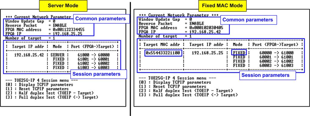
Figure 4‑1 Display current parameter result
· Common parameter: There are four Common parameters.
1) Window Update Gap: Set threshold value to transmit Window update packet. Valid value is 0x00 – 0x3F (0-63). The unit size of threshold value is 1 Kbyte. Default value is 0 (disable Window update feature).
2) Reverse Packet: This flag is enabled to allow the IP sending the retransmitted packet when IP waits Windows update packet returned from the target for long time. Default value is ENABLE.
3) FPGA MAC address: 48-bit hex value to be MAC address of FPGA. Default value is 0x000102030405 (Client/Fixed MAC mode) or 0x001122334455 (Server mode).
4) FPGA IP: IP address of FPGA. Default value is 192.168.25.42 (Client/Fixed mode) or 192.168.25.25 (Server mode).
Before displaying Session parameters, the number of target devices set by user is displayed. The example shows one target applied, so the same Target MAC address and IP address are set to all sessions.
While the initialization mode of the first session can be set to Server, Client, or Fixed MAC, the rest sessions of the same target device are automatically set to Fixed MAC mode. The details of Session parameter are described as below.
· Session parameter: There are three or four Session parameters, depending on mode.
1) Target MAC address (displayed when running Fixed MAC mode only): 48-bit hex value to be MAC address of the target device. Default value is 0x554433221100.
2) Target IP address: IP address of the target device (25 Gb Ethernet on PC). Default value is 192.168.25.25 (Client/Fixed MAC mode) or 192.168.25.42 (Server mode).
3) Initialization mode: TOE25G-IP initialization mode which can be selected to ‘0’ (Server), ‘1’ (Client), or ‘2’ (Fixed MAC).
4) Port number (FPGA->Target): Port number of FPGA is the left-hand side value and port number of target device is the right-hand side value. This parameter is assigned to each session individually. Default parameters of 4 sessions for Client/Fixed MAC mode are 60000 - 60003 and 61000 - 61003, respectively. While default parameters of 4 sessions for Server mode are 61000 - 61003 and 60000 - 60003, respectively.
To change parameters, user can set by using menu [1].
4.2 Reset TCPIP parameters
Select ‘1’ to reset the IP and change IP parameters.
This menu is used to change IP parameters or send reset to TOE25G-IPs. After selecting this menu, the current parameters are displayed on the console. User enters ‘x’ to use the same parameters while other keys are entered to change parameters. After the parameters are fixed, all TOE25G-IPs are reset and start the initialization process.
The description of each parameter is shown in topic 4.1 (Display TCPIP parameter) and the range of each parameter is described as follows.
Note: When running the test by using FPGA – FPGA communication, please refer following rules.
1. The mode on two FPGAs must be set to Server – Client, Client – Fixed MAC, or Fixed MAC – Fixed MAC.
2. When running Server – Client mode and user needs to reset parameters on the Server FPGA, the Client FPGA must be also reset. Also, the Server must be reset before the Client to wait until ARP request sent by the Client.
3. Parameter of two FPGAs must be matched, as following list.
a. Target IP of board#1 = FPGA IP of board#2
b. FPGA IP of board#1 = Target IP of board#2
c. Target port number of board#1 = FPGA port number of board#2 (each session)
d. FPGA port number of board#1 = Target port number of board#2 (each session)
1) Mode: Input ‘0’, ‘1’, or ‘2’ to initialize the IP as Client mode, Server mode, or Fixed MAC mode, respectively.
2) Reverse Packet: Set ‘0’ to disable or ‘1’ to enable this feature.
3) Window Update Gap: Set threshold value to transmit Window update packet. Valid value is 0x00 – 0x3F (0-63). The unit size of threshold value is 1 Kbyte. Default value is 0 (disable Window update feature).
4) FPGA MAC address: Input 12 digits of hex value. Add “0x” as a prefix to input as hex value.
5) FPGA IP address: A set of four decimal digits is separated by “.”. The valid range of each decimal digit is 0-255.
6) Number of target: The total number of target devices that connects with multiple TOE25G-IPs. Valid range is 1-4 (Number of TOE25G-IP in this demo).
After that the user starts setting the parameters of each session.
1) Target MAC address (displayed when running Fixed MAC mode only): Input 12 digits of hex value. Add “0x” as a prefix to input as hex value.
2) Target IP address: A set of four decimal digits, similar to FPGA IP address. This value is IP address of Test PC.
Note: Target MAC address and Target IP address for different target devices (when number of targets is more than one) must be set to different value.
3) Number of sessions: The total number of TCPIP sessions in this target device. Valid range depends on the number of targets. For one target device system, the number of sessions can be set to 1 - 4.
4) FPGA port number of the current session: Valid range is 0-65535.
5) Target port number of the current session: Valid range is 0-65535
Note: Port number of different session in the same target device must be assigned by different value.
After finishing parameter assignment, the assigned parameters are displayed on the console. Next, the reset signal is sent to all IPs to initialize the IPs by using new parameters. Finally, “IP initialization complete” is shown after the IPs complete initialization process, as shown in Figure 4‑2 and Figure 4‑3.

Figure 4‑2 Change IP parameter result for Server and Client mode
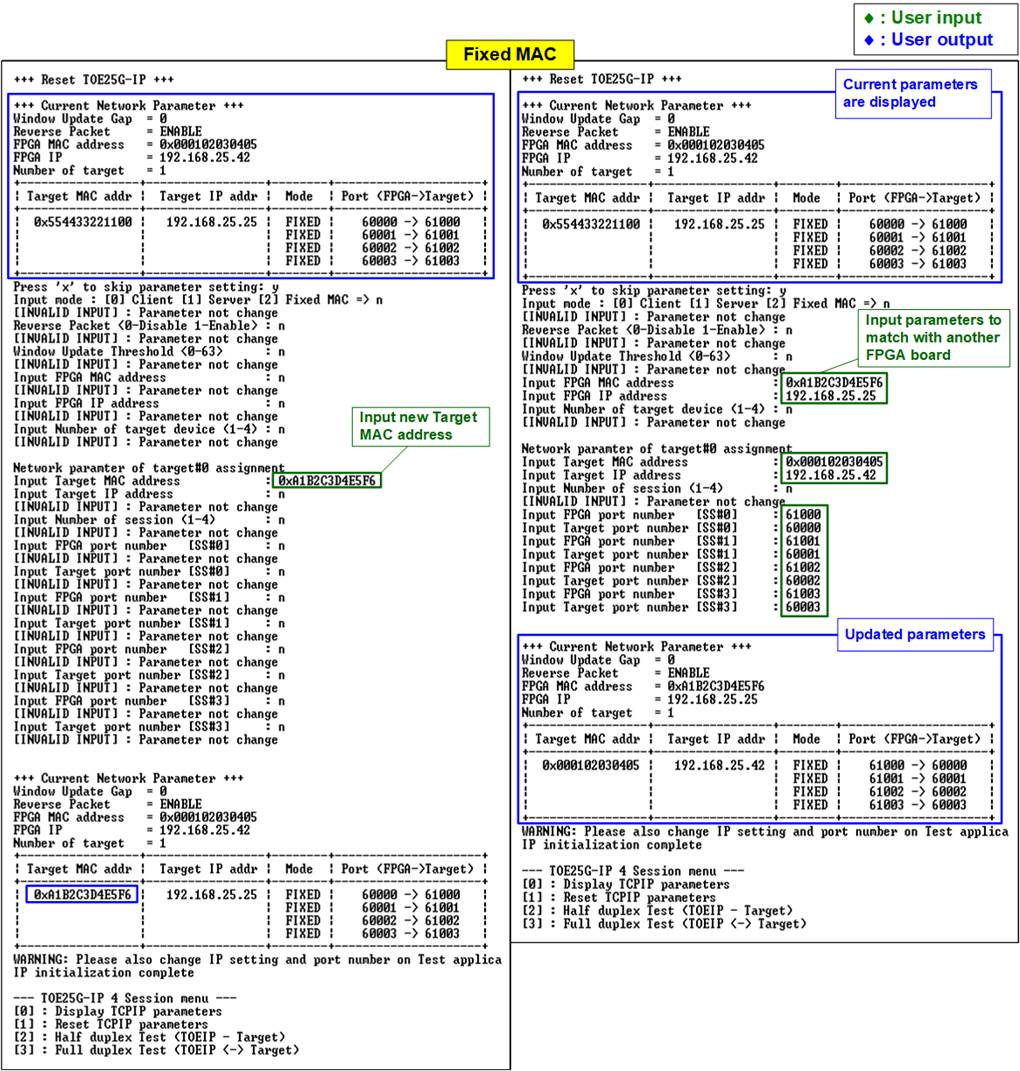
Figure 4‑3 Change IP parameter result for Fixed MAC mode
4.3 Half-duplex Test
To transfer data in single direction between two FPGAs, select ‘2’ to run half-duplex test on the FPGA@board1 and FPGA@board2 for running Send test and Receive test, respectively. The half-duplex test allows user to assign test parameters on console for each session separately. The sequence to run the test when Server runs Send test and Client runs Receive test is shown as follows.
Note:
1. The mode set in half-duplex test to be the Server or Client mode is applied for opening the connection. The end-point as Client creates the connection while the end-point as Server waits for connection. The two FPGAs must set different mode, one is Client and another is Server to open the port by different mode.
2. However, the close connection mode is controlled by test mode, Send test or Receive test. The Send end-point is the one that start closing the connection while the Receive end-point waits for the close connection request.
3. The Client-Server mode for the open connection does not relate to the initialization mode which is set to be Client, Server, or Fixed-MAC mode.
1) On FPGA@board1 console which is running Send test, input test parameters under half-duplex test menu.
a) Input test mode: ‘0’-Disable and skip to assign the next session, ‘1’-Send test.
b) Input transfer size: Unit of transfer size is byte. Valid value is 0x10 - 0xF_FFFF_FFF0. The input must be aligned to 16. The input is decimal unit when input only digit number. User adds “0x” to be a prefix for hexadecimal unit.
c) Input packet size: Unit of packet size is byte. Valid value is 16 – 8960. The input must be aligned to 16. The input is decimal unit when input only digit number. User adds “0x” to be a prefix for hexadecimal unit.
d) Input operation mode: Input ‘1’ to transfer as Server mode.
2) If all inputs on FPGA@board1 console are valid, the parameters of the active session are displayed. “Wait connection” is displayed to wait until Client (FPGA@board2) sends request for the new connection.
3) On FPGA@board2 console which is running Receive test, input test parameters under half-duplex test menu.
a) Input test mode: ‘0’-Disable and skip to assign the next session, ‘2’-Receive test.
b) Input transfer size: Unit of transfer size is byte. Valid value is 0x10 - 0xF_FFFF_FFF0. The input must be aligned to 16. The input is decimal unit when input only digit number. User adds “0x” to be a prefix for hexadecimal unit. This value must be equal to total transfer size in step 1b) on the selected session.
c) Input data verification mode: Input ‘1’ to enable data verification sent from FPGA@board1.
d) Input operation mode: Input ‘0’ to transfer as Client mode.
4) If all inputs on FPGA@board2 console are valid, “Press any key to proceed” is shown on the console. After pressing some key on FPGA@board2 console, the ports are created.
5) Current amount of transferred data is displayed on both consoles every second. In this example, the FPGA@board1 console shows the amount of transmitted data while the FPGA@board2 console shows the amount of received data. “Closed” might be displayed on the console after all data in the session are completely transferred.
6) “Half-duplex test complete” is displayed on both consoles after all connection are closed. Finally, total amount of transferred data and performance of each session are displayed on both consoles. Also, “Total performance” is displayed on console if multiple sessions are run.
Note: When running FPGA <-> FPGA test environment, total performance is almost equal to the sum of each session performance. There is less overhead time when the ports are all opened by firmware automatically.
Figure 4‑4 shows the example of two-session half duplex test (FPGA-to-FPGA) when using normal packet size. The left window is the Send test console (Server or FPGA@board#1) and the Receive test console (Client or FPGA@board#2).

Figure 4‑4 Two-session half-duplex test (FPGA-to-FPGA) by using normal packet size
Figure 4‑5 shows the example of four-session half duplex test (FPGA-to-FPGA) when using normal packet size. Comparing to Figure 4‑4, the performance of running two-session and four-session is not different.
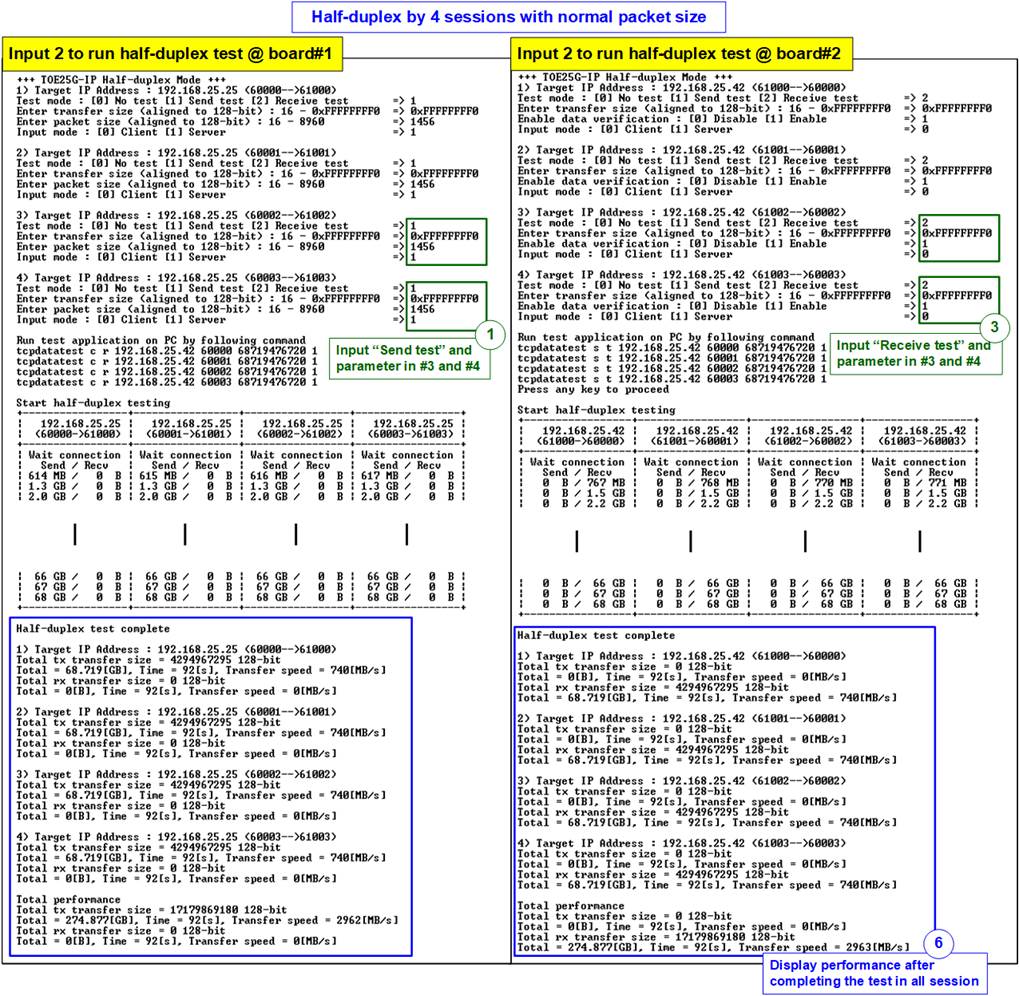
Figure 4‑5 Four-session half-duplex test (FPGA-to-FPGA) by using normal packet size
Figure 4‑6 shows the example of four-session half duplex test (FPGA-to-FPGA) when using jumbo frame size. Comparing to Figure 4‑5, the performance of using jumbo frame size is better than using small packet size.
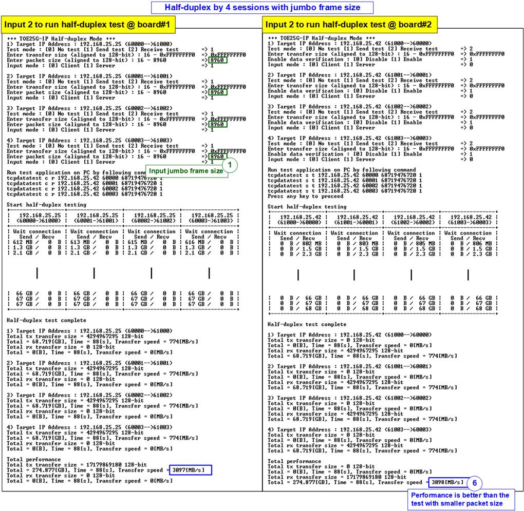
Figure 4‑6 Four-session half-duplex test (FPGA-to-FPGA) by using jumbo frame size
4.4 Full duplex Test
To transfer data in both directions between two FPGAs, select ‘3’ to run full-duplex test on the FPGA@board1 and FPGA@board2. The full-duplex test allows user to assign test parameters for each session separately. The sequence to run the test is shown as follows.
Note: The mode set in full-duplex test to open and close the connection is assigned. The Client creates and terminates the connection while the Server waits for the open and the terminate connection request. The two FPGAs must set different mode, one is Client and another is Server. The Client-Server setting for opening/closing the connection does not relate to the initialization mode which is set to be Client, Server, or Fixed-MAC mode.
1) On FPGA@board1 console running as Server, input test parameters under full-duplex test menu.
a) Input test mode: ‘0’-Disable and skip to assign the next session, ‘1’-Full-duplex test.
b) Input transfer size: Unit of transfer size is byte. Valid value is 0x10 - 0xF_FFFF_FFF0. The input must be aligned to 16. The input is decimal unit when input only digit number. User adds “0x” to be a prefix for hexadecimal unit.
c) Input packet size: Unit of packet size is byte. Valid value is 16 – 8960. The input must be aligned to 16. The input is decimal unit when input only digit number. User adds “0x” to be a prefix for hexadecimal unit.
d) Input data verification mode: Input ‘1’ to enable data verification sent from FPGA@board2.
e) Input operation mode: Input ‘1’ to transfer as Server mode.
2) If all inputs on FPGA@board1 console are valid, the parameters of the active session are displayed. “Wait connection” is displayed to wait until Client (FPGA@board2) sends request for the new connection.
3) On FPGA@board2 console running as Server, input test parameters under full-duplex test menu.
a) Input test mode: ‘0’-Disable and skip to assign the next session, ‘1’-Full-duplex test.
b) Input transfer size: Unit of transfer size is byte. Valid value is 0x10 - 0xF_FFFF_FFF0. The input must be aligned to 16. The input is decimal unit when input only digit number. User adds “0x” to be a prefix for hexadecimal unit. This value must be equal to total transfer size in step 1b) on the selected session.
c) Input packet size: Unit of packet size is byte. Valid value is 16 – 8960. The input must be aligned to 16. The input is decimal unit when input only digit number. User adds “0x” to be a prefix for hexadecimal unit.
d) Input data verification mode: Input ‘1’ to enable data verification sent from FPGA@board1.
e) Input operation mode: Input ‘0’ to transfer as Client mode.
4) If all inputs on FPGA@board2 console are valid, “Press any key to proceed” is shown. After pressing some key on FPGA@board2 console, the ports are created.
5) Current amount of transferred data is displayed on both consoles every second. Both consoles show the amount of transferred data in both directions. “Closed” might be displayed on the console after all data in the session are completely transferred.
6) “Full-duplex test complete” is displayed on both consoles after all connection are closed. Finally, total amount of transferred data and performance of each session are displayed on both consoles. Also, “Total performance” is displayed on console if running the test more than one session.
Note: Total performance is almost equal to the sum of each session performance because all ports are opened with less overhead time when using firmware.
Figure 4‑7 shows the example of two-session full duplex test (FPGA-to-FPGA) when using jumbo frame size. The left window is the Server console (FPGA@board#1) while the right window is the Client console (FPGA@board#2).

Figure 4‑7 Two-session full duplex test (FPGA-to-FPGA) with jumbo frame size
Figure 4‑8 shows the example of four-session full duplex test (FPGA-to-FPGA) when using jumbo frame size. Comparing to Figure 4‑7, the performance of running two-session or four-session is not different.

Figure 4‑8 Four-session full duplex test (FPGA-to-FPGA) with jumbo frame size
5 Revision History
|
Revision |
Date |
Description |
|
1.0 |
16-Jan-23 |
Initial version release |