TOE25G-IP with Two-Port Demo Instruction
Rev1.0 6-Jul-23
1 Overview
This document shows the example to run TOE25G-IP with two-port demo. The first port is for transferring high-speed TCP payload data with TOE25G-IP while the second port is the slow-speed connection. For slow-port connection, two demos are implemented, Ping test and DHCP test. The details of high-speed connection of two-port demo are similar to the standard demo.
The test environment uses one FPGA board connecting with one Test PC for transferring Ethernet packet on 25GbE network. The transfer performance of high-speed port is limited by Test PC resource. To achieve the best performance, it needs to run the demo by using two FPGA boards which integrates TOE25G-IP for transferring the data each other. Please see more details from TOE25G-IP instruction document.
In the document, topic 2 shows the example to set up 25Gb Ethernet card on Test PC to get the good performance for transferring Ethernet packet via 25GbE network. Next, topic 3 shows the example console to run Ping demo. Finally, topic 4 shows the example console to run DHCP demo. More details of each topic are described as follows.
2 PC Setup
Before running demo, please check the network setting on PC. The example for setting 25Gb Ethernet card is described as follows.
2.1 IP Setting
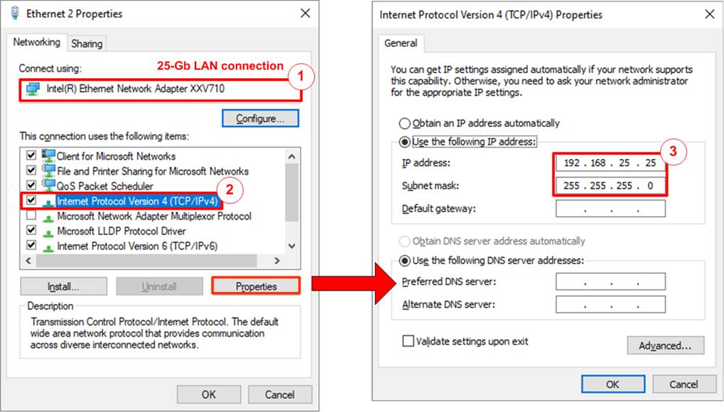
Figure 2‑1 Setting IP address for PC
1) Open Local Area Connection Properties of 25-Gb connection, as shown in the left window of Figure 2‑1.
2) Select “TCP/IPv4” and then click Properties.
3) Set IP address = 192.168.25.25 and Subnet mask = 255.255.255.0, as shown in the right window of Figure 2‑1.
2.2 Speed and Frame Setting

Figure 2‑2 Set frame size = Jumbo frame
1) On Local Area Connection Properties window, click “Configure” as shown in Figure 2‑2.
2) On Advanced Tab, select “Jumbo Packet”. Set Value to “9014 Bytes” for Jumbo Frame support or set value to “Disabled” for non-Jumbo Frame support, as shown in the bottom window of Figure 2‑2.
3) Select “Speed & Duplex”. Set value to “25 Gbps Full Duplex” for running 25-Gigabit transfer test, as shown in Figure 2‑3.
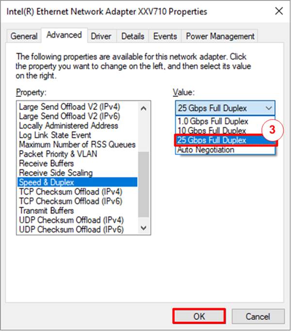
Figure 2‑3 Set link speed = 25 Gbps
4) Select “Interrupt Moderation” and set value to “Disable”.
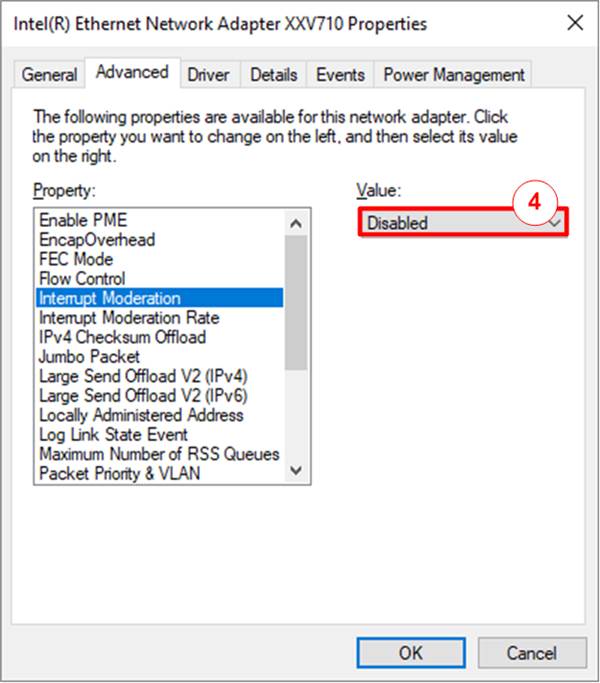
Figure 2‑4 Interrupt Moderation
5) Click “OK” button to save and exit all setting windows.
2.3 Power Option Setting
1) Open Control Panel and select Power Options as shown in the left window of Figure 2‑5.
2) Change setting to High Performance as shown in the right window of Figure 2‑5.
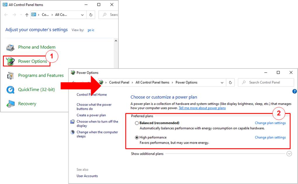
Figure 2‑5 Power options
3 Ping demo
Before running the demo, please prepare test environment for VCK190 development board, as described in “dg_toeudp25gip_fpgasetup_xilinx” document. After finishing downloading configuration file, the main menu is displayed. Comparing to the standard demo, menu [5] is additional for running Ping reply test. The details of each menu are described as follows.
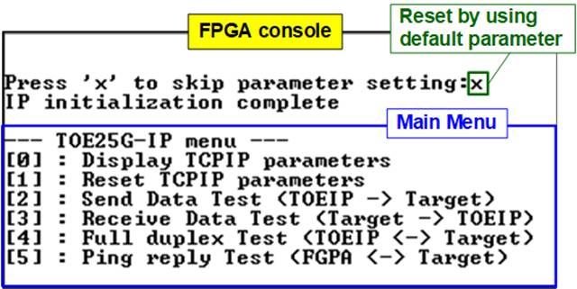
Figure 3‑1 Main menu of Ping demo
3.1 Display TCPIP parameters
Select ‘0’ to check current parameter in the demo. There are eight parameters in Client/Server mode or nine parameters in Fixed MAC mode displayed on the console.
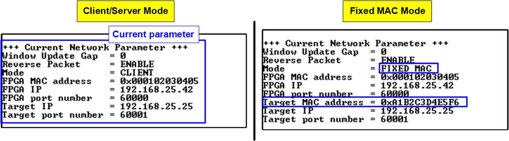
Figure 3‑2 Display current parameter result
1) Window Update Gap: Set threshold value to transmit window update packet. Valid value is 0x00 – 0x3F (0-63). The unit size of threshold value is 1 Kbyte. Default value is 0 (disable window update feature).
2) Reverse Packet: This flag is enabled to allow the IP sending the retransmitted packet when IP waits Windows update packet returned from the target for long time. Default value is ENABLE.
3) Mode: Set mode to TOE25G-IP to initialize in Server, Client, or Fixed MAC. To run with PC, please input ‘0’ to initialize the IP in client mode.
4) FPGA MAC address: 48-bit hex value to be MAC address of FPGA. Default value is 0x000102030405.
5) FPGA IP: IP address of FPGA. Default value is 192.168.25.42.
Note: This value is used to be server IP address parameter for test application on PC.
6) FPGA port number: Port number of FPGA. Default value is 60000.
Note: This value is used to be server port for test application on PC.
7) Target MAC address (displayed when running Fixed MAC mode only): 48-bit hex value to be MAC address of the target device. Default value is 0x554433221100.
8) Target IP: IP address of the target device (25 Gb Ethernet on PC). Default value is 192.168.25.25.
9) Target port number: Port number of the target device to transfer 25 Gb Ethernet data. Default value is 60001.
To change some parameters, user can set by using menu [1].
3.2 Reset TCPIP parameters
Select ‘1’ to reset the IP and change IP parameters.
This menu is used to change IP parameters or send reset to TOE25G-IP. After user selects this menu, the current parameters are displayed on the console. User enters ‘x’ to use the same parameters while other keys are entered to change some parameters. After the parameters are fixed, TOE25G-IP is reset and start the initialization process.
There are 7-9 parameters to set in this menu. Each parameter is verified by CPU. The parameter is updated to TOE25G-IP when the input is valid. If the input is not valid, the parameter does not change. After user inputs all parameters, the IP is reset. The description of each parameter is shown in topic 3.1(Display TCPIP parameter) and the range of each parameter is described as follows.
1) Mode: Input ‘0’ to initialize the IP as client mode.
Note: When TestPC and FPGA are connected in different network which cannot communicate by ARP process, it needs to run TOE25G-IP in Fixed MAC mode to set MAC address manually via the console instead of using ARP process
2) Reverse Packet: Set ‘0’ to disable or ‘1’ to enable this feature.
3) Window Update Gap: Set threshold value to transmit window update packet. Valid value is 0x00 – 0x3F (0-63). The unit size of threshold value is 1 Kbyte. Default value is 0 (disable window update feature).
4) FPGA MAC address: Input 12 digits of hex value. Add “0x” as a prefix to input as hex value.
5) FPGA IP address: A set of four decimal digits is separated by “.”. The valid range of each decimal digit is 0-255.
Note: This parameter is not displayed when running in DHCP demo.
6) FPGA port number: Valid range is 0-65535.
7) Target MAC address (displayed when running Fixed MAC mode only): Input 12 digits of hex value. Add “0x” as a prefix to input as hex value.
8) Target IP address: A set of four decimal digits, similar to FPGA IP address. This value is IP address of Test PC.
9) Target port number: Valid range is 0-65535.
After finishing parameter assignment, new parameter set is displayed on the console. Next, the reset signal is sent to the IP to initialize the IP by using new parameters. Finally, “IP initialization complete” is shown after IP completes initialization process, as shown in Figure 3‑3.
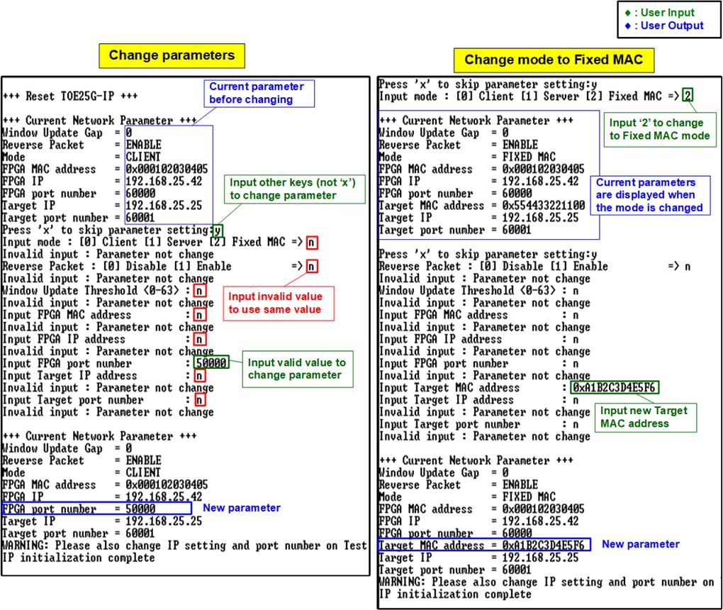
Figure 3‑3 Change IP parameter in client mode result
3.3 Send Data Test
To transfer data from FPGA to PC, select ‘2’ to run send data test on FPGA and run “tcpdatatest.exe” on PC to receive data. User inputs test parameters for sending data on the console. On PC, user inputs test parameters of “tcpdatatest” to receive data via Command prompt. The sequence to run the test is shown as follows.
1) On FPGA console, input three parameters under send data test menu.
a) Input transfer size: Unit of transfer size is byte. Valid value is 0x10 - 0xF_FFFF_FFF0. The input must be aligned to 16. The input is decimal unit when input only digit number. User adds “0x” to be a prefix for hexadecimal unit.
b) Input packet size: Unit of packet size is byte. Valid value is 16 – 8960. The input must be aligned to 16. The input is decimal unit when input only digit number. User adds “0x” to be a prefix for hexadecimal unit.
Note: If packet size is more than 1456, the packet output from TOE25G-IP is jumbo frame. In this case, Test PC must support jumbo frame.
c) Input Mode: Mode of FPGA to transfer data. Input ‘1’ to transfer as server mode.
2) If all inputs are valid, the recommended parameters to run test application on PC is displayed. Next, “Wait Open connection …” is displayed to wait the application running on PC.
3) On Command prompt, input test parameters following the recommended value. There are six parameters for “tcpdatatest”.
>> tcpdatatest <mode> <dir> <server IP> <server port> <bytelen> <pattern>
a) Mode: Input ‘c’ to run Test PC as a client.
b) Dir: Input ‘r’ to run Test PC for receiving and verifying test data from FPGA
c) Server IP: Input the same value as IP address of FPGA
d) Server port: Input the same value as port number of FPGA
e) Bytelen: Input the same value as “Input transfer size” of step 1a)
f) Pattern: Input ‘1’ to verify data from FPGA or ‘0’ to not verify data
4) After running the test application, the port is created. Current transfer size is displayed on the console (transmit size) and Command prompt (received size) every second. “Send data complete” is displayed on the console after all data are sent.
5) FPGA closes the connection. Finally, total transfer size and performance are displayed on the console (transmit performance) and Command prompt (receive performance).
Figure 3‑4 shows the example of send data test when using non-jumbo frame size with enabling data verification on Command prompt. The left window is FPGA console operating as Server and the right window is Command prompt on PC operating as Client.
Figure 3‑5 shows the example of send data test when using jumbo frame size.
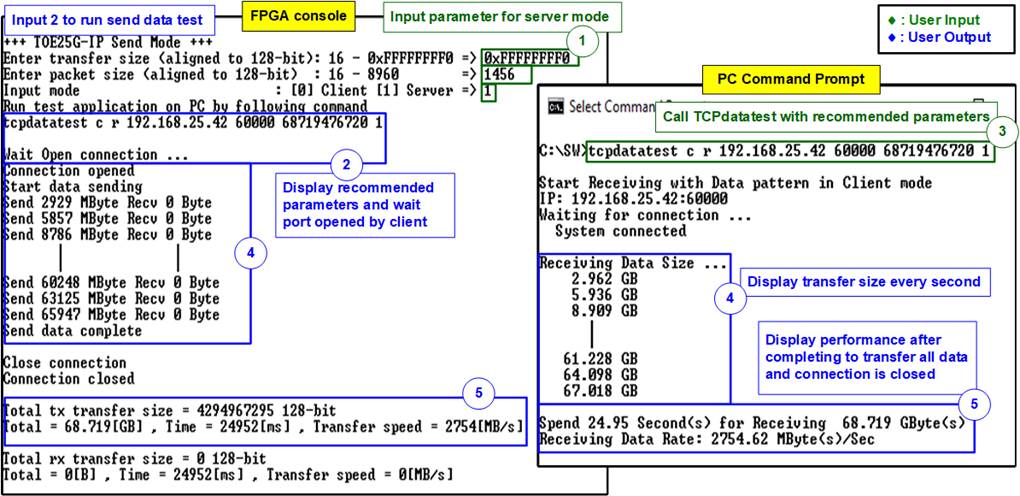
Figure 3‑4 Send data test by using non-jumbo frame
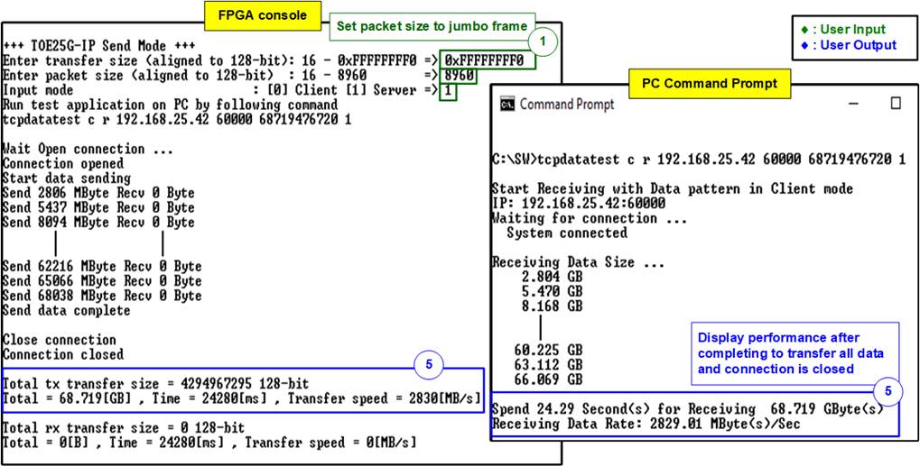
Figure 3‑5 Send data test by using jumbo frame
If the input is invalid, “Out-of-range input” or “Invalid input” is displayed. After that, the operation is cancelled, as shown in Figure 3‑6 - Figure 3‑8.

Figure 3‑6 Error from invalid transfer size

Figure 3‑7 Error from invalid packet size
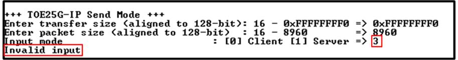
Figure 3‑8 Error from invalid mode
3.4 Receive Data Test
To transfer data from PC to FPGA, select ‘3’ to run receive data test on FPGA and run “tcpdatatest.exe” on PC to send data. User inputs test parameters on FPGA for receiving data on FPGA console. On PC, user inputs test parameters of “tcpdatatest” to send data on Command prompt. The sequence to run the test is shown as below.
1) On FPGA console, input three parameters in receive data test.
a) Input transfer size: Unit of transfer size is byte. Valid value is 0x10 - 0xF_FFFF_FFF0. The input must be aligned to 16. The input is decimal unit when input only digit number. User adds “0x” to be a prefix for hexadecimal unit.
b) Input data verification mode: Set ‘0’ to disable data verification or ‘1’ to enable data verification sent from PC.
c) Input Mode: Mode of FPGA to transfer data. Input ‘1’ to transfer as server mode.
2) If inputs are valid, the recommended parameters to run test application on PC are displayed. Next, “Wait Open connection …” is displayed to wait until the application on PC running.
3) On Command prompt, input test parameters following the recommended value. There are six parameters for “tcpdatatest”.
>> tcpdatatest <mode> <dir> <server IP> <server port> <bytelen> <pattern>
a) Mode: Input ‘c’ to run Test PC as a client.
b) Dir: Input ‘t’ to run Test PC for sending test data to FPGA
c) Server IP: Input the same value as IP address of FPGA
d) Server port: Input the same value as port number of FPGA
e) Bytelen: Input the same value as “Input transfer size” of step 1a)
f) Pattern: Input the same value as “Input data verification mode” of step 1b). Select ‘0’ to send dummy data or ‘1’ to send incremental data.
4) After running the test application, the port is created. Current transfer size is displayed on FPGA console (receive size) and Command prompt (transmit size) every second.
5) “Connection closed” and “Received data completed” are displayed on FPGA console after PC finishes sending all data and closing the connection. Finally, total transfer size and performance are displayed on FPGA console (receive performance) and Command prompt (transmit performance).
Figure 3‑9 shows the example of receive data test when data verification mode on FPGA is disabled and dummy data is sent by PC. The left window is test result on FPGA console while the right window is test result on Command prompt.
Figure 3‑10 shows the example of receive data test when data verification mode on FPGA is enabled and incremental data is sent by PC.
Figure 3‑11 shows the example of error when data verification is failed. In the example, the error is caused from mismatch verification mode value. FPGA enables data verification while “tcpdatatest” sends dummy data. The error message is displayed on FPGA console.
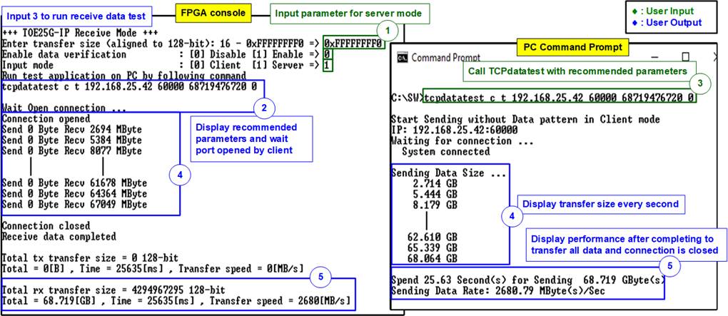
Figure 3‑9 Receive data test without data verification
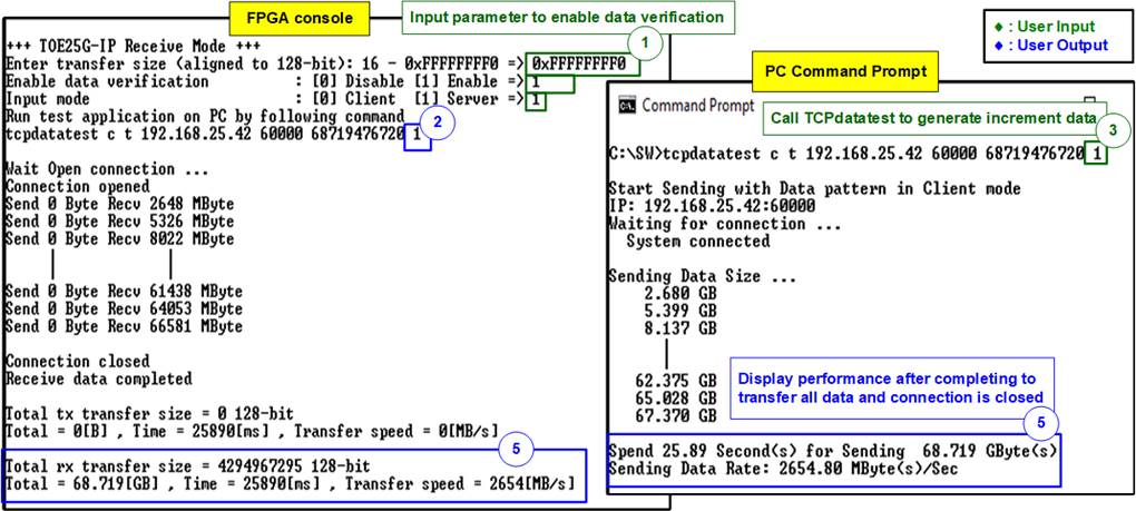
Figure 3‑10 Receive data test when enabling data verification

Figure 3‑11 Receive data test when data verification is failed
3.5 Full duplex Test
Select ‘4’ to run full duplex test to transfer data between FPGA and PC in both directions at the same time. User inputs test parameters on FPGA console and on PC Command prompt. “tcp_client_txrx_40G” application is called on PC to send and receive data by using the same port number. The sequence to run the test is shown as below.
1) On FPGA console, input four parameters in full duplex test.
a) Input transfer size: Unit of transfer size is byte. Valid value is 0x10 - 0xF_FFFF_FFC0. The input must be aligned to 16. The input is decimal unit when input only digit number. User adds “0x” to be a prefix for hexadecimal unit. This value must be equal to total transfer size, set on test application.
b) Input packet size: Unit of packet size is byte. Valid value is 16 – 8960. The input must be aligned to 16. The input is decimal unit when input only digit number. User adds “0x” to be a prefix for hexadecimal unit.
c) Input data verification mode: Set ‘0’ to disable data verification or ‘1’ to enable data verification sent from PC.
d) Input Mode: Mode of FPGA to transfer data. Input ‘1’ to transfer as Server mode.
2) If all inputs are valid, the recommended parameters to run test application on PC are displayed. Next, “Wait Open connection …” is displayed to wait the application on PC running.
3) On Command prompt, input test parameters following the recommended value. There are four parameters for “tcp_client_txrx_40G”.
>> tcp_client_txrx_40G <server IP> <server port> <bytelen> <pattern>
a) Server IP: Input the same value as IP address of FPGA
b) Server port: Input the same value as port number of FPGA
c) ByteLen: Total transfer size in byte unit. Input the same value as “Input transfer size” of step 1a).
d) Pattern: Input the same value as “Input data verification mode” of step 1c). Select ‘0’ to send dummy data or ‘1’ to send incremental data.
4) After running the test application, the port is created. During transferring data, current transfer size is displayed on FPGA console and Command prompt every second.
5) “Send data complete” is displayed on FPGA console after finishing sending data, receiving data, and closing the connection. Finally, total transfer size and performance are displayed on FPGA console and Command prompt.
Repeat Step 4) – 5) as forever loop until the user enters any keys on FPGA console and then enters “Ctrl+C” on Command prompt.
As shown in Figure 3‑12 - Figure 3‑13, transfer performance when running full duplex without data verification shows better performance than the test with data verification. Running without data verification takes less PC resource. The left window is the test result on FPGA console while the right window is the test result on Command prompt.
Note: There is an issue when running tcp_client_txrx_40G application on some Windows10 versions. The performance is much reduced. The results displayed in Figure 3‑12 and Figure 3‑13 use Windows10 Pro version1909. While using Windows10 Pro version2004 or 20H2, the performance is less than 200 MB/s.
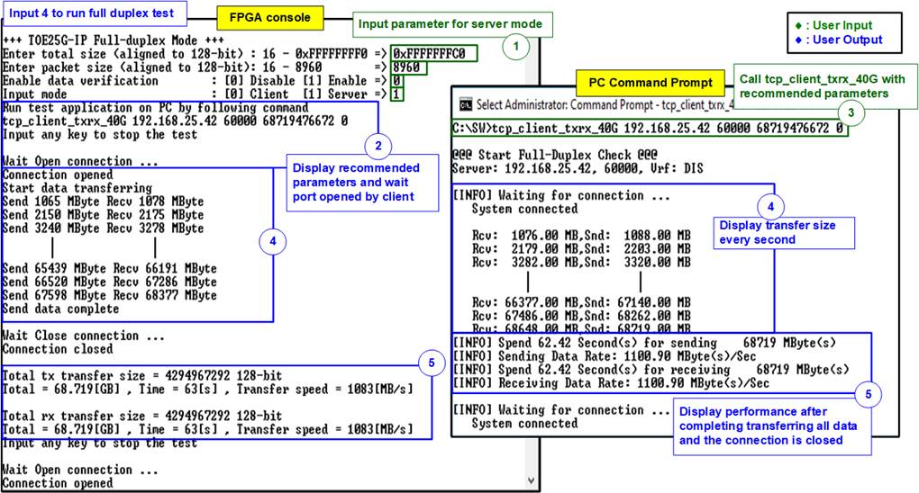
Figure 3‑12 Full duplex test without data verification
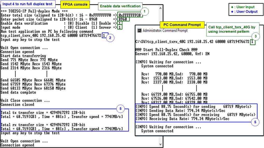
Figure 3‑13 Full duplex test with data verification
3.6 Ping reply Test
Select ‘5’ to run Ping reply mode. After selecting this menu, “Press any key to exit Ping test” is displayed on the console as shown in Figure 3‑14. After that, user can type “ping <FPAG board IP address>” command on Command prompt to start Ping command test, as shown in Figure 3‑15.
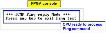
Figure 3‑14 Ping reply mode result on FPGA console
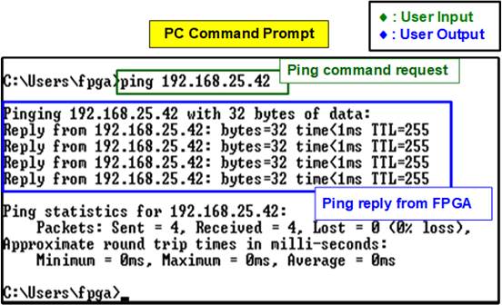
Figure 3‑15 Ping command result on PC
User can exit this menu by pressing any key(s) to the console. After that, main menu is displayed as shown in Figure 3‑16.

Figure 3‑16 Main menu is displayed after exit the Ping test
4 DHCP demo
Before running DHCP demo, Test PC must be prepared to perform a DHCP server. In this demo, the application “dhcpsrv” (version 2.5.2) is applied for running on Windows OS. After that, prepare the test environment as described in “dg_toeudp25gip_fpgasetup_xilinx” document. When finishing downloading configuration file to FPGA, the main menu of DHCP test is displayed. The menu for testing the fast port connection by TOE25G-IP has the same operation as Ping test. Please see more details from topic 3.1 - 3.5. This topic describes only menu [5] Release IP address. The details of running DHCP demo are described as follows.
Note: When running DHCP demo, FPGA IP address is not allowed to be assigned by user to avoid the conflict with FPGA IP address that is assigned by DHCP.
4.1 DHCP Server Setting
The procedure to run DHCP server software interface as shown in Figure 4‑1.

Figure 4‑1 DHCP server software
1) From the installation package, user selects “dhcpwiz.exe”. After the software wizard is displayed, click “Next >” to start DHCP server configuration.
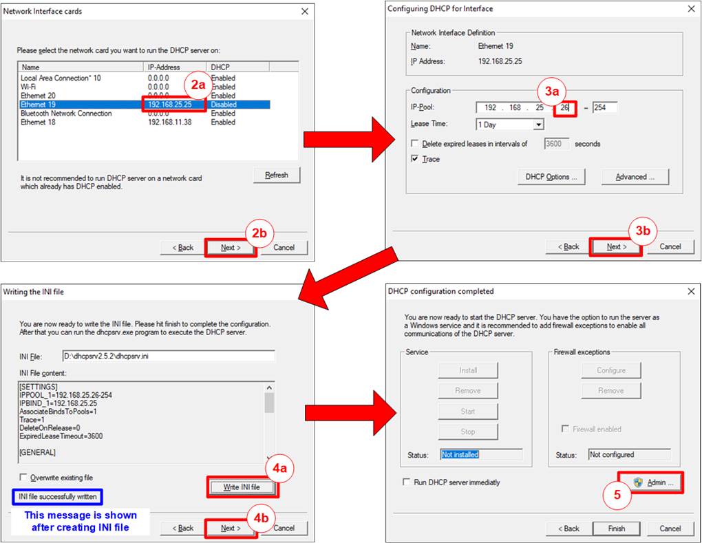
Figure 4‑2 DHCP server configuration
2) Select the network interface that is connected to FPGA board. In this demo, the connection which uses 192.168.25.25 is applied. After that, click “Next >” to continue the next step.
3) Assign the IP address range that is allowed to assign to DHCP client. The example sets 26 to be the first IP address for DHCP client. After that, click “Next >” to continue the next step.
4) Click “Write INI file” to create the script file to run the server. The message “INI file successfully written” is displayed after clicking the button. Next, click “Next >” to continue the next step.
5) Click “Admin” for entering the administration mode. The DHCP server software is able to run after allowing the software for admin mode.
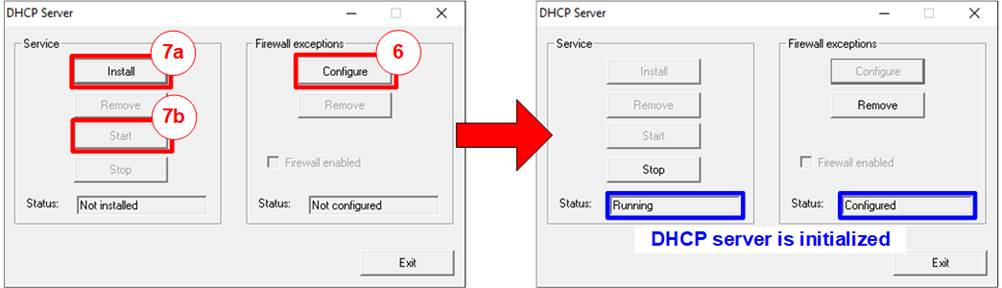
Figure 4‑3 DHCP server software running
6) Click the “Configure” button in the Firewall exceptions block. Then, the status of Firewall exceptions is changed to “Configured”.
7) Click the “Install” button in the Service block and then click the “Start” button in the Service block. After that, the Status is changed to “Running” and the DHCP server is initialized.
More details about the DHCP server software are provided from the website.
https://www.dhcpserver.de/cms/
4.2 DHCP test
4.2.1 Boot menu
Please prepare test environment following the FPGA setup document. However, the system boot-up procedure is slightly different in the last step because the boot menu for IP address assignment by DHCP is displayed.
Note: Please make sure that the DHCP server is run, as described in topic 4.1, before continuing the next step.
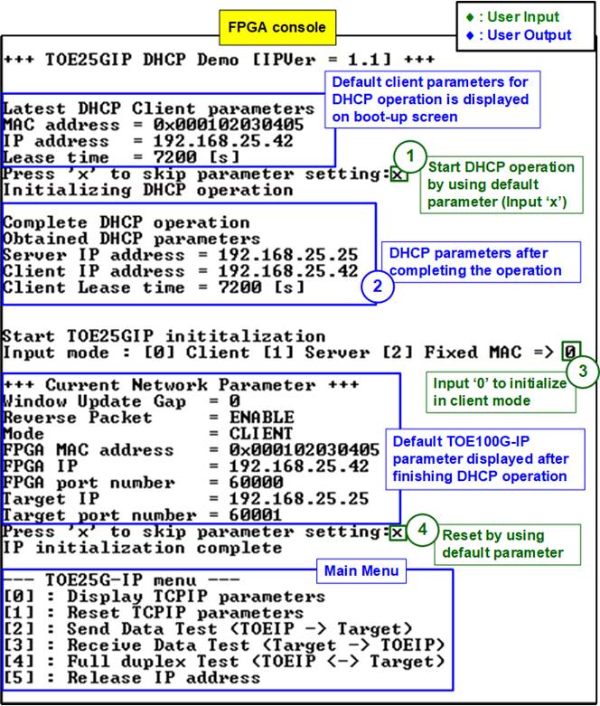
Figure 4‑4 Message after system boot-up of DHCP test
1) The default parameters for IP address assignment by DHCP is displayed. User enters ‘x’ to start DHCP operation by using the default parameters. If other keys are set, the menu to change DHCP parameters are displayed, similar to menu [5] (Release IP address). After that, the DHCP operation is started.
2) After DHCP operation is completed, the parameters assigned by DHCP server are displayed on the console.
3) The menu to start TOE100G-IP initialization is displayed. Input ‘0’ to start TOE100G-IP initialization in client mode (asking PC MAC address by sending ARP request). After that, the default parameters for TOE100G-IP are displayed on the console.
4) User enters ‘x’ to skip parameter setting for using default parameters to run TOE100G-IP initialization. If user enters other keys, the menu for changing parameter is displayed, similar to menu [1] (Reset TCPIP parameters).
4.2.2 Release IP address
Select ‘5’ to release IP address of FPGA that is assigned by DHCP server. This menu can be used to change FPGA MAC address or FPGA IP address. When finishing IP release process, “Release IP address completed” is displayed, as shown in Figure 4‑5.

Figure 4‑5 Release IP address complete
After that, it returns to the boot menu to display the latest DHCP parameters on the console. User enters ‘x’ to use the same parameters for the DHCP operation. Other keys are entered to change some parameters. There are three parameters to set in this menu.
1) MAC address: This parameter is the FPGA MAC address. Default value is 0x000102030405. To change the parameter, input 12 digits of hex value. Add “0x” as a prefix to input as hex value.
2) IP address: This parameter is the preferred IP address requested to DHCP server. If the DHCP server allows the FPGA to use this IP address, it will be assigned to the FPGA IP address. Otherwise, the DHCP server assigns other value to be the FPGA IP address. The default value is 192.168.25.42. To change the requested parameter, input a set of four decimal digits is separated by “.”. The valid range of each decimal digit is 0-255.
3) Lease time: This parameter is the requested lease time in second unit that sent to DHCP server. However, the final value is determined by DHCP server. Default value is 7200 second. The valid range is 600 (decimal unit) - 0xFFFFFFFF (hex unit).
Note: According the DHCP protocol, 0xFFFFFFFF is reserved for infinite lease time.
Each parameter is verified by CPU. The parameter is updated when the input is valid. If the input is not valid, the parameter does not change. After user inputs all parameters, the CPU starts the DHCP operation using the assigned parameters. If the DHCP operation is completed, the parameters that the DHCP server set to the FPGA are displayed. The parameters may be different from the requested parameters if the DHCP server changes it. Three parameters are displayed on the console.
1) Server IP address: The IP address of DHCP server.
2) Client IP address: The IP address that is assigned to be the FPGA IP address.
3) Client Lease time: The IP address lease time assigned by DHCP server in the second unit. User needs to perform the release IP address before this lease time is run out.
Note: The demo does not implement the timer to check lease time. If auto release must be implemented, please add Timer to the test system.
After completing the DHCP operation and displaying DHCP parameters, the message “Start TOE25GIP initialization” is displayed. Finally, the CPU automatically starts the Reset TCPIP parameters process to reset and re-assign the TOE25G-IP and its parameters, as shown in Figure 4‑6.
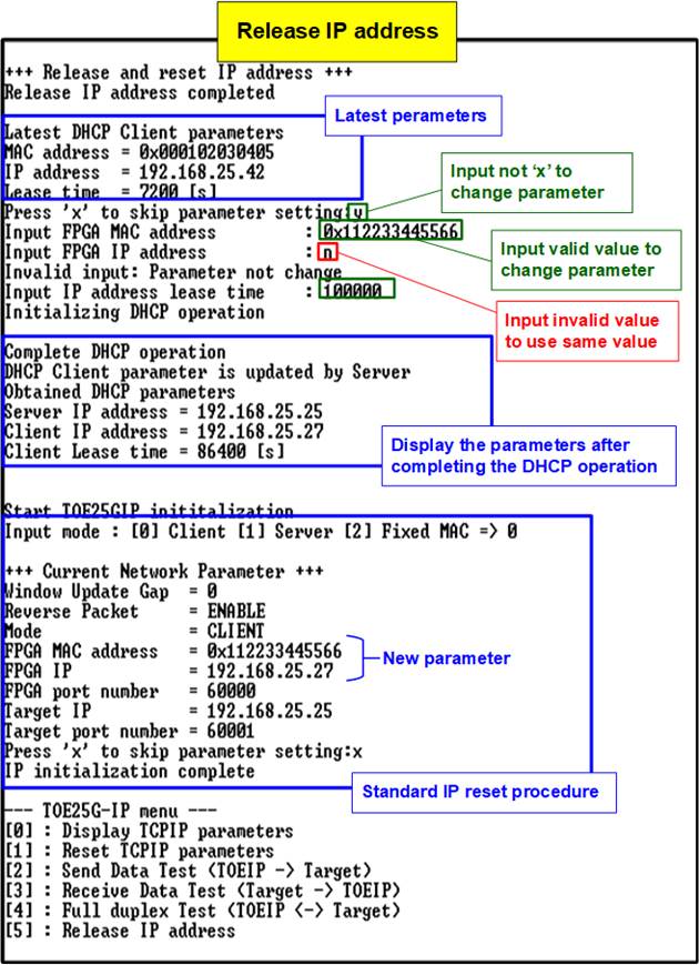
Figure 4‑6 Re-initialize the DHCP operation
5 Revision History
|
Revision |
Date |
Description |
|
1.0 |
27-May-22 |
Initial version release |