TOE40G-IP Demo Instruction
Rev1.2 15-Jun-23
Part A TOE40G-IP demo by using FPGA and PC..
Part B TOE40G-IP demo by using two FPGAs
8.3 Send Data Test (server to client)
8.4 Receive Data Test (client to server)
1 Overview
The demo is designed to run TOE40G-IP for transferring 40 Gb Ethernet data by using TCP/IP protocol. The destination device may be Test PC or TOE40G-IP on another FPGA as shown in Figure 1‑1.
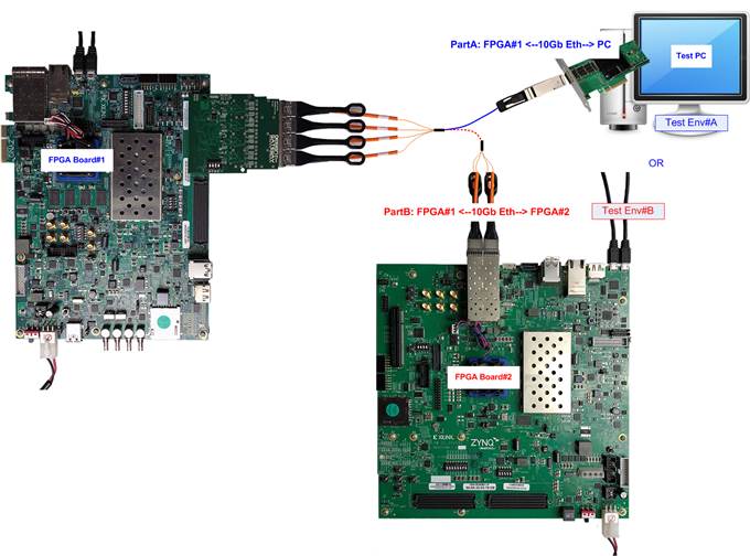
Figure 1‑1 Two test environments for the demo
To describe the step for running the demo in more details, the document is split into two parts following the test environment, i.e. “Part A TOE40G-IP demo by using FPGA and PC” and “Part B TOE40G-IP demo by using two FPGAs”. User interface to set test parameters and monitor the operation on FPGA board is Serial console by using UART interface.
Part A TOE40G-IP demo by using FPGA and PC
To transfer data between TOE40G-IP and Test PC, user selects to run half-duplex or full-duplex demo. “tcpdatatest” application is run on Test PC for half-duplex demo (sending data from TOE40G-IP to PC or receiving data from PC to TOE40G-IP). “tcp_client_txrx_40G.exe” application is run on Test PC for full-duplex demo (sending and receiving data with PC at the same time). More details of the demo are described as follows.
2 Environment Setup
To operate TOE40G-IP demo, please prepare following test environment.
1) FPGA development boards (ZCU102/ZCU106/KCU105)
2) PC with 40 Gigabit Ethernet support or 40 Gigabit Ethernet card
3) QSFP+ to four SFP+ cable for network connection between FPGA board and 40G Ethernet card that plug-in on PC
4) For ZCU106/KCU105, prepare AB15-SFPFMC board (provided by Design Gateway) for connecting 4 SFP+ Cable to FPGA
5) Two micro USB cable for programming FPGA and Serial console, connecting between FPGA board and PC
6) “tcpdatatest.exe” and “tcp_client_txrx_40G.exe” which are test application provided by Design Gateway, installed on PC
7) Serial console software such as HyperTerminal (Baudrate=115,200 Data=8 bit Non-parity Stop=1), installed on PC
8) Vivado tool for programming FPGA, installed on PC
Note: Test result in this document is captured by using following test environment.
[1] 40G Network Adapter: Intel XL710-Q1
[2] 40-Gigabit QSFP to 4x10-Gigabit SFP+ cable
https://www.finisar.com/active-optical-cables/fcbn510qe2cxx
[3] PC: Motherboard ASUS Z170-K, Intel i7-6700K CPU, 32 GB RAM
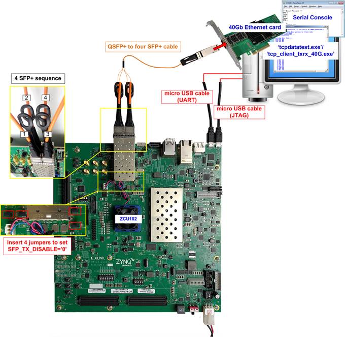
Figure 2‑1 TOE40G-IP demo environment setup on ZCU102

Figure 2‑2 TOE40G-IP demo environment
setup on ZCU106

Figure 2‑3 TOE40G-IP demo environment setup on KCU105
3 PC Setup
Before running demo, network setting on PC is required. The example to set the network is described as follows.
3.1 IP Setting
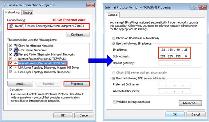
Figure 3‑1 Setting IP address for PC
1) Open Local Area Connection Properties of 40-Gb connection, as shown in left window of Figure 3‑1.
2) Select “TCP/Ipv4” and then click Properties.
3) Set IP address = 192.168.40.25, and Subnet mask = 255.255.255.0, as shown in right window of Figure 3‑1.
3.2 Speed and Frame Setting

Figure 3‑2 Set frame size = jumbo frame
1) On Local Area Connection Properties window, click “Configure” as shown in Figure 3‑2.
2) On Advanced Tab, select “Jumbo Packet”. Set Value to “9014 Bytes” for Jumbo Frame support or set value to “Disabled” for non-Jumbo Frame support, as shown in bottom window of Figure 3‑2.
3) On Advanced Tab, select “Performance Options” and click “Properties” button.
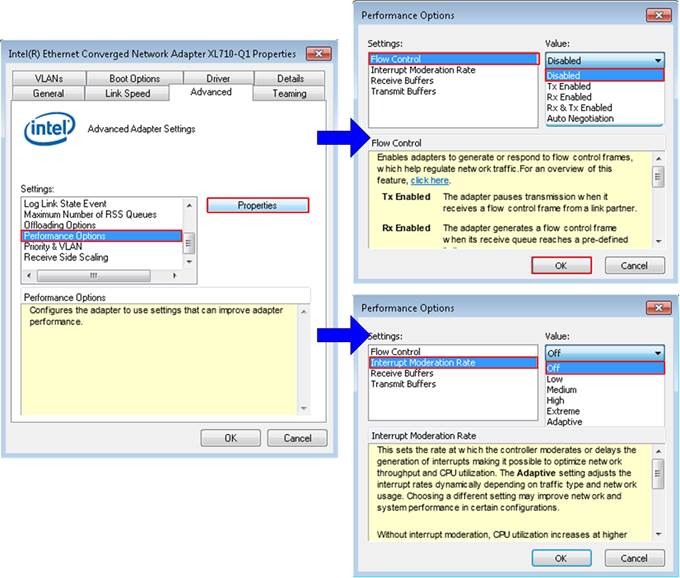
Figure 3‑3 Performance option
4) Set “Flow Control” = Disabled.
5) Set “Interrupt Moderation Rate” = Off.
6) Click “OK” button to save and exit all setting windows.
3.3 Power Option Setting
1) Open Control Panel and select Power Options as shown in the left window of Figure 3‑4.
2) Change setting to High Performance as shown in the right window of Figure 3‑4.
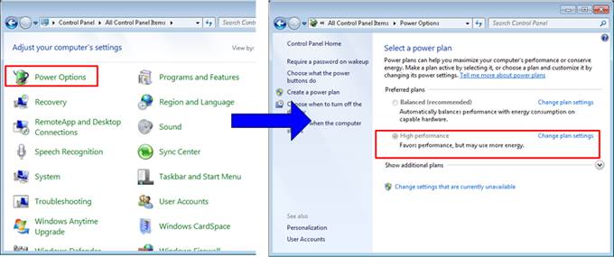
Figure 3‑4 Power options
4 FPGA board setup
1) Power off system.
2) For ZCU102/ZCU106 board, set ARM Boot mode of ARM to be JTAG by setting SW6[4:1] to be ON, ON, ON, ON.
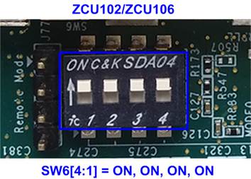
Figure 4‑1 Set ARM boot mode to JTAG for ZCU102/ZCU106
3) For ZCU102 board, insert jumper to J16, J17, J42, and J54 to set SFP_TX_DISABLE=’0’.
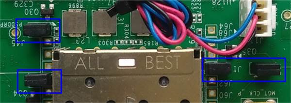
Figure 4‑2 Set SFP[0]-[3] TX DISABLE for ZCU102
4) Connect two micro USB cable from FPGA board to PC for JTAG programming and USB UART (Serial Console).
5) Connect power supply to FPGA development board.
6) Insert QSFP cable side to PC and insert four SFP+ cables to FPGA board.
a) For ZCU102, insert four SFP+ cable to SFP+ on board. Please check channel number of four cables to match with Figure 4‑3.
Figure 4‑3 Four SFP+ cable connecting to ZCU102 board
b) For ZCU106/KCU105, insert AB15-SFPFMC adapter to FMC-HPC0 on FPGA board. After that, insert four SFP+ cable to SFP+ on AB15-SFPFMC adapter. Please check channel number of four cables to match with Figure 4‑4 for each board.
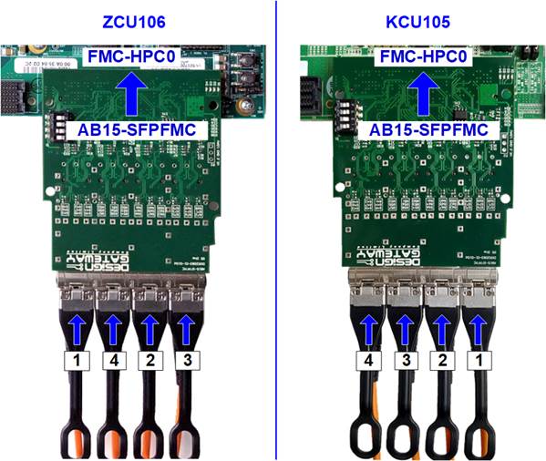
Figure 4‑4 Four SFP+ cable connecting to ZCU106/KCU105 board
7) Power on FPGA board.
8) Open Serial console. When connecting FPGA board to PC, many COM ports from FPGA connection are detected and displayed on Device Manager.
In case of KCU105, select Standard COM port.
In case of ZCU102/ZCU106, select COM port number of Interface0 (COM15 in right side of Figure 4‑5) for Serial console.
On Serial console, use following setting: Buad rate=115,200, Data=8 bit, Non-Parity, and Stop = 1.

Figure 4‑5 COM port number for Serial console
9) Download and program configuration file and firmware to FPGA board.
a) For ZCU102/ZCU106, open Vivado TCL shell and change current directory to download folder which includes demo configuration file. Type “toe40cputest_zcu102 (or zcu106).bat, as shown in Figure 4‑6.
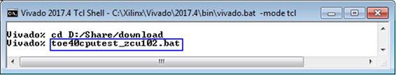
Figure 4‑6 Example command script for download to ZCU102/ZCU106 by Vivado tool
b) For KCU105, configure FPGA by using Vivado, as shown in Figure 4‑7.

Figure 4‑7 Program FPGA by Vivado for KCU105
10) Input ‘0’ to initialize TOE40G-IP in client mode (ask PC MAC address by sending ARP request).
11) Default parameter in client mode is displayed on the console.
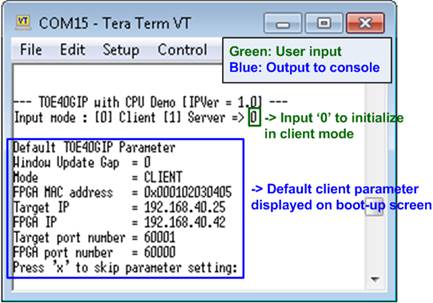
Figure 4‑8 Message after system boot-up
12) User inputs ‘x’ to skip parameter setting and use default parameters for system initialization, as shown in Figure 4‑9. If user inputs other keys, the menu to change parameter will be displayed. The example to change parameter is shown in topic 5.2.

Figure 4‑9 Initialization complete
Note: Transfer performance depends on Test PC resource in Test platform.
5 Main menu
5.1 Display current parameter
Select ‘0’ to check current parameter in the demo. There are seven parameters displayed on the console.

Figure 5‑1 Display current parameter result
1) Window Update Gap: Set threshold value to transmit window update packet. Valid value is 0x00 – 0x3F (0-63). The unit size of threshold value is 1 Kbyte. Default value is 0 (disable window update feature).
2) Mode: Set mode to TOE40G-IP to act as server or client. To run with PC, please input ‘0’ to initialization the IP in client mode.
3) FPGA MAC address: 48-bit hex value to be MAC address of FPGA. Default value is 0x000102030405.
4) Target IP: IP address of destination device (40 Gb Ethernet card on PC) to transfer 40 Gb Ethernet data. Default value is 192.168.40.25.
5) FPGA IP: IP address of FPGA. Default value is 192.168.40.42.
Note: This value is used to be server IP address parameter for test application on PC.
6) Target port number: Port number of destination device to transfer 40 Gb Ethernet data. Default value is 60001.
7) FPGA port number: Port number of FPGA. Default value is 60000.
Note: This value is used to be server port for test application on PC.
To change some parameters, user can set by using menu [1].
5.2 Reset TOE40G-IP
Select ‘1’ to reset the IP and change IP parameters.
This menu is used to change IP parameters. After user selects this menu, the current parameters are displayed. User inputs ‘x’ to use same parameters or inputs other keys to change parameters. Seven parameters are designed to change from user. If user inputs invalid value such as ‘n’, the parameter will not change. After setting parameters completely, IP is reset. More details of each parameter are described as follows.
1) Window Update Gap: Set threshold value to transmit window update packet. Valid value is 0x00 – 0x3F (0-63). The unit size of threshold value is 1 Kbyte. Default value is 0 (disable window update feature).
2) Mode: Input ‘0’ to initialization the IP as client mode.
3) FPGA MAC address: Input 12-digit of hex value. Add “0x” as a prefix to input as hex value.
4) FPGA IP address: A set of four decimal digits is separated by “.”. The valid range of each decimal digit is 0-255.
5) FPGA port number: Valid range is 0-65535.
6) Target IP address: A set of four decimals like FPGA IP address. This value is IP address of Test PC.
7) Target port number: Valid range is 0-65535.
After complete to assign all parameters, new parameters are displayed on the console. Next, reset signal is sent to the IP to load new parameters. Finally, “IP initialization complete” is shown after IP completes initialization process, as shown in Figure 5‑2.

Figure 5‑2 Change IP parameter result
5.3 Send Data Test
To transfer data from FPGA to PC, select ‘2’ to run send data test on FPGA and prepare “tcpdatatest.exe” on PC to receive data. User inputs test parameters on FPGA through Serial console and inputs test parameters on PC through command prompt. The sequence to run the test is shown as below.
1) On Serial console, input three parameters in send data test.
a) Input transfer size: Unit of transfer size is byte. Valid value is 32 - 0x1F_FFFF_FFE0. The input must be aligned to 32. User selects to input as decimal or hexadecimal unit. To input as hex value, user adds “0x” as a prefix.
b) Input packet size: Unit of packet size is byte. Valid value is 32 – 8960. The input must be aligned to 32. User selects to input as decimal or hexadecimal unit. To input as hex value, user adds “0x” as a prefix.
c) Input Mode: Mode of FPGA to transfer data. Input ‘1’ to set server mode.
2) If inputs are valid, recommended parameters to run test application on PC and “Wait Open connection …” will be displayed.
3) On Command prompt, input test parameters following the recommended value. There are six parameters for “tcpdatatest”.
>> tcpdatatest <mode> <dir> <server IP> <server port> <bytelen> <pattern>
a) Mode: Input ‘c’ to run Test PC as a client.
b) Dir: Input ‘r’ to run Test PC for receiving test data from FPGA
c) Server IP: Input same value as IP address of FPGA
d) Server port: Input same value as port number of FPGA
e) Bytelen: Input same value as “Input transfer size” of step 1a)
f) Pattern: Input ‘1’ to verify data from FPGA
4) After running test application, the port is created. Current transfer size is displayed on Serial console and Command prompt every second. “Send data complete” is displayed on Serial console after all data are sent.
5) FPGA closes the connection. Finally, total transfer size and performance are displayed on Serial console and Command prompt.
Figure 5‑3 shows the example of send data test when using non-jumbo frame size. Left window is Serial console on FPGA operating as server and right window is Command prompt on PC operating as client.
Figure 5‑4 shows the example of send data test when using jumbo frame size.
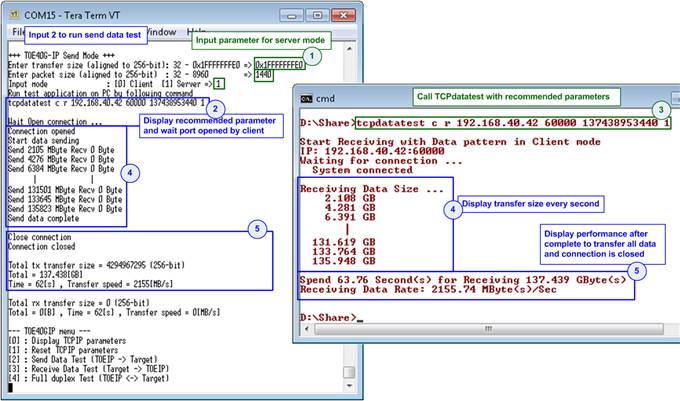
Figure 5‑3 Send data test by using non-jumbo frame
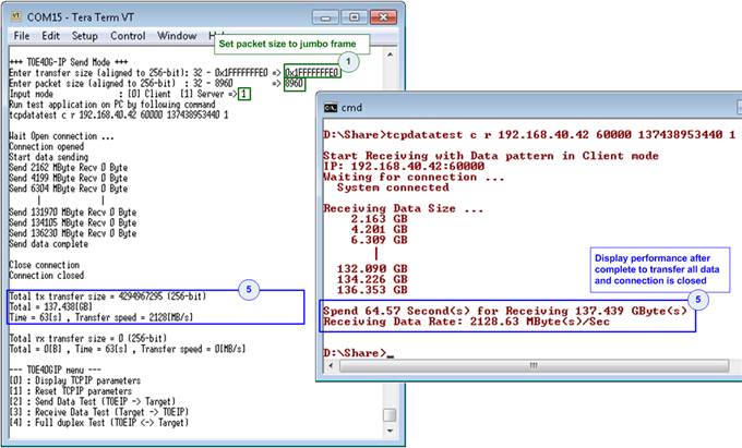
Figure 5‑4 Send data test by using jumbo frame
If the input is invalid, “Out-of-range input”/”Invalid input” will be displayed and the operation will be cancelled, as shown in Figure 5‑5 - Figure 5‑7.
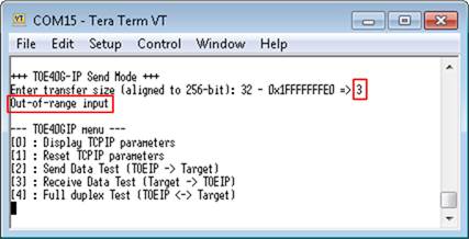
Figure 5‑5 Error from invalid transfer size
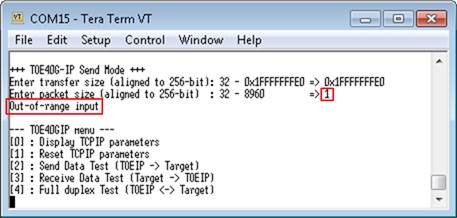
Figure 5‑6 Error from invalid packet size
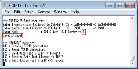
Figure 5‑7 Error from invalid mode
5.4 Receive Data Test
To transfer data from PC to FPGA, select ‘3’ to run receive data test on FPGA and prepare “tcpdatatest.exe” on PC to send data. User inputs test parameters on FPGA through Serial console and inputs test parameters on PC through Command prompt. The sequence to run the test is shown as below.
1) On Serial console, input three parameters in receive data test.
a) Input transfer size: Unit of transfer size is byte. Valid value is 32 - 0x1F_FFFF_FFE0. The input must be aligned to 32. User selects to input as decimal or hexadecimal unit. To input as hex value, user adds “0x” as a prefix.
b) Input data verification mode: Set ‘0’ to disable data verification or ‘1’ to enable data verification sent from PC.
c) Input Mode: Mode of FPGA to transfer data. Input ‘1’ to set server mode.
2) If inputs are valid, recommended parameters to run test application on PC and “Wait Open connection …” will be displayed.
3) On Command prompt, input test parameters following the recommended value. There are six parameters for “tcpdatatest”.
>> tcpdatatest <mode> <dir> <server IP> <server port> <bytelen> <pattern>
a) Mode: Input ‘c’ to run Test PC as a client.
b) Dir: Input ‘t’ to run Test PC for sending test data to FPGA
c) Server IP: Input same value as IP address of FPGA
d) Server port: Input same value as port number of FPGA
e) Bytelen: Input same value as “Input transfer size” of step 1a)
f) Pattern: Input same value as “Input data verification mode” of step 1b). Select ‘0’ to send dummy data or ‘1’ to send increment data.
4) After running test application, the port is created. Current transfer size is displayed on Serial console and Command prompt every second.
5) “Connection closed” and “Receive data completed” are displayed on Serial console after PC completes to send all data and closes the connection. Finally, total transfer size and performance are displayed on Serial console and Command prompt.
Figure 5‑8 shows the example of receive data test when disable data verification mode on FPGA and send dummy data on PC. The left window is test result on Serial console while the right window is test result on Command prompt.
Figure 5‑9 shows the example of receive data test when enable data verification mode on FPGA and send increment data on PC. The performance when disable data verification is better than the performance when enable data verification because generating dummy data uses less PC resource than increment data.
Figure 5‑10 shows the example of error when data verification is failed. In the example, the error is caused from mismatch verification mode value. FPGA enables data verification while “tcpdatatest” sends dummy data. The error message is displayed on Serial console.

Figure 5‑8 Receive data test without data verification
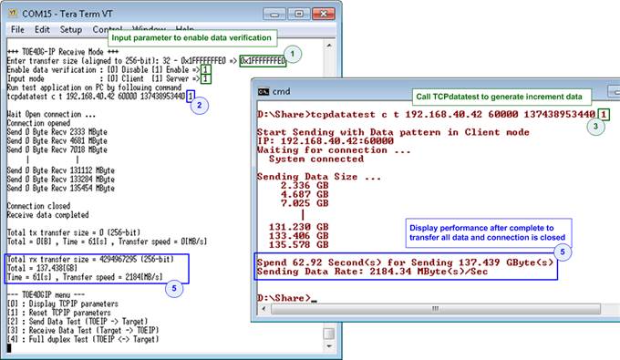
Figure 5‑9 Receive data test when enable data verification

Figure 5‑10 Receive data test when data verification is failed
5.5 Full duplex Test
Select ‘4’ to run full duplex test to transfer data between FPGA and PC in both directions at the same time. User inputs test parameters on FPGA through Serial console and inputs test parameters on PC through Command prompt. The sequence to run the test is shown as below.
1) On Serial console, input four parameters in full duplex test.
a) Input transfer size: Unit of transfer size is byte. Input “0x7FFFFFC0” which is equal to total transfer size setting on test application.
b) Input packet size: Unit of packet size is byte. Valid value is 32 – 8960. The input must be aligned to 32. User selects to input as decimal or hexadecimal unit. To input as hex value, user adds “0x” as a prefix.
c) Input data verification mode: Set ‘0’ to disable data verification or ‘1’ to enable data verification sent from PC.
d) Input Mode: Mode of FPGA to transfer data. Input ‘1’ to set server mode.
2) If inputs are valid, recommended parameters to run test application on PC and “Wait Open connection …” will be displayed.
3) On Command prompt, input test parameters following the recommended value. There are three parameters for “tcp_client_txrx_40G”.
>> tcp_client_txrx_40G <server IP> <server port> <pattern>
a) Server IP: Input same value as IP address of FPGA
b) Server port: Input same value as port number of FPGA
c) Pattern: Input same value as “Input data verification mode” of step 1b). Select ‘0’ to send dummy data or ‘1’ to send increment data.
4) After running test application, the port is created. Current transfer size is displayed on Serial console and Command prompt every second.
5) “Send data complete” is displayed on Serial console after it completes to send and receive all data and closes the connection. Finally, total transfer size and performance are displayed on Serial console and Command prompt.
Step 4) – 5) run in forever loop until user cancels the operation. To cancel the operation, input “Ctrl+C” on Command prompt, and then input any keys on Serial console.
As shown in Figure 5‑11 - Figure 5‑12, transfer performance when running full duplex without data verification shows the better performance than the test with data verification. The left window is the test result on Serial console while the right window is the test result on Command prompt.
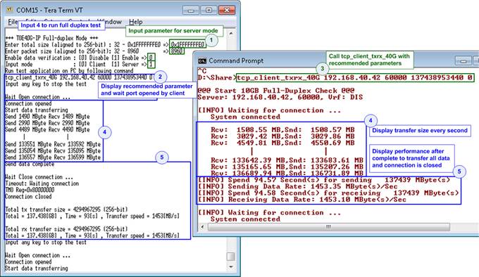
Figure 5‑11 Full duplex test without data verification

Figure 5‑12 Full duplex test with data verification
Part B TOE40G-IP demo by using two FPGAs
6 Environment Setup
As shown in Figure 6‑1, to run TOE40G-IP with CPU demo by using two FPGAs, please prepare following test environment.
1) Two FPGA development boards (ZCU102/ZCU106/KCU105)
Note: In test environment, two FPGA boards could be same or different board. Figure 6‑1 shows the example demo by using ZCU102 and ZCU106 board.
2) 4 SFP+ to SFP+ cables for network connection two between FPGA board
3) For ZCU106, prepare AB15-SFPFMC board (provided by Design Gateway) for connecting 4 SFP+ Cables to FPGA
4) Connects two micro USB cables for programming FPGA and Serial console between each FPGA board and PC (two sets are used for two FPGA boards)
5) Serial console software such as HyperTerminal (Baudrate=115,200 Data=8 bit Non-parity Stop=1), installed on PC
6) Vivado tool for programming FPGA, installed on PC
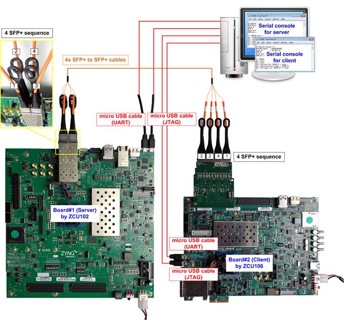
Figure 6‑1 TOE40G-IP with CPU demo (FPGA<->FPGA) by ZCU102 and ZCU106
7 FPGA board setup
Please follow topic 4 FPGA board setup to prepare FPGA board and 4 SFP+ cable connections for running the demo. After two FPGA boards have been configured completely, Serial console displays the menu to select client mode or server mode. The step after FPGA configuration is described as follows.
1) Open Serial console for board#1 and board#2. In this document, COM12 is Serial console for FPGA board#1 which is set to server mode and COM16 is Serial console for FPGA board#2 which is set to client mode.
a. Set ‘1’ on Serial console of FPGA board#1 for running server mode. Set ‘0’ on Serial console of FPGA board#2 for running client mode.
b. Default parameters for server or client are displayed on the console, as shown in Figure 7‑1.

Figure 7‑1 Input mode
2) Input ‘x’ to use default parameters or other keys to change parameters. Please complete to set parameters on server Serial console before client Serial console. Server must be reset to start IP initialization before client.
After finish parameters setting, IP starts initialization process. “IP initialization complete” is displayed when all initialization sequence are completed. Finally, main menu is displayed on Serial console.
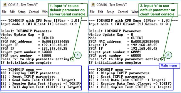
Figure 7‑2 Main menu
8 Main menu
8.1 Display current parameter
Select ‘0’ to check current parameter in the demo. There are seven parameters displayed on Serial console.

Figure 8‑1 Display current parameter result
1) Window Update Gap: Set threshold value to transmit window update packet. Valid value is 0x00 – 0x3F (0-63). The unit size of threshold value is 1 Kbyte. Default value is 0 (disable window update feature).
2) Mode: Set mode to TOE40G-IP to act as server or client. Input ‘0’ for client and ‘1’ for server.
3) FPGA MAC address: 48-bit hex value to be MAC address of FPGA. Default value is 0x000102030405 (client mode) or 0x001122334455 (server mode).
4) Target IP: IP address of destination device to transfer 40 Gb Ethernet data. Default value is 192.168.40.25 (client mode) or 192.168.40.42 (server mode).
5) FPGA IP: IP address of FPGA. Default value is 192.168.40.42 (client mode) or 192.168.40.25 (server mode).
6) Target port number: Port number of the destination device to transfer 40 Gb Ethernet data. Default value is 60001 (client mode) or 60000 (server mode).
7) FPGA port number: Port number of FPGA. Default value is 60000 (client mode) or 60001 (server mode).
To change some parameters, user can set by using menu [1].
8.2 Reset TOE40G-IP
Select ‘1’ to reset the IP and change IP parameters.
This menu is used to change IP parameters. After user selects this menu, the current parameters are displayed. User inputs ‘x’ to use same parameters or inputs other keys to change parameters. Seven parameters are designed to change from user. If user inputs invalid value such as ‘n’, the parameter will not change. After setting parameters completely, IP is reset. More details of each parameter are described as follows.
Note:
1. When user desires to reset parameters on server, the client FPGA must be also reset. Server must be reset firstly to wait ARP request sending from client.
2. Parameter of client and server must be matched, i.e.
a. Target IP of server = FPGA IP of client
b. FPGA IP of server = Target IP of client
c. Target port number of server = FPGA port number of client
d. FPGA port number of server = Target port number of client
1) Window Update Gap: Set threshold value to transmit window update packet. Valid value is 0x00 – 0x3F (0-63). The unit size of threshold value is 1 Kbyte. Default value is 0 (disable window update feature).
2) Mode: Input ‘0’ (client) or ‘1’ (server) to determine FPGA initialization mode. The valid range is 0-1. It needs to set different mode for two FPGA boards. One board is client and another board is server.
3) FPGA MAC address: Input 12-digit of hex value. Add “0x” as a prefix to input as hex value.
4) FPGA IP address: A set of four decimal digits is separated by “.”. The valid range of decimal digit is 0-255.
5) FPGA port number: Valid range is 0-65535.
6) Target IP address: A set of four decimals like FPGA IP address.
7) Target port number: Valid range is 0-65535.
After complete to assign all parameters, new parameters are displayed on Serial console. Next, reset signal is sent to the IP to load new parameters. Finally, “IP initialization complete” is shown after IP completes initialization process, as shown in Figure 8‑2.
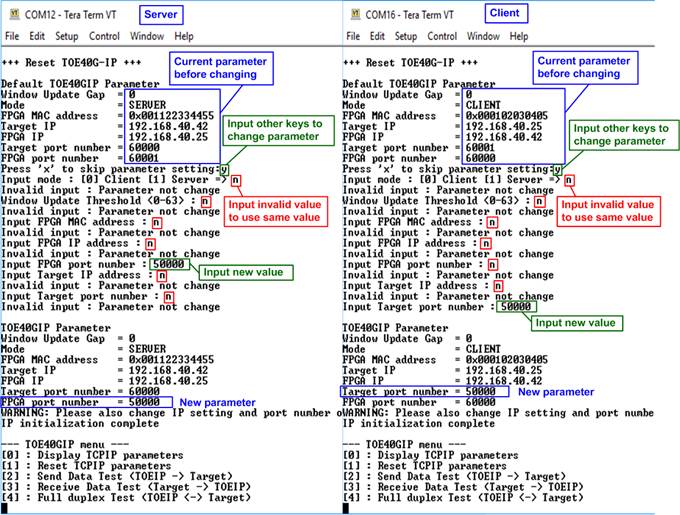
Figure 8‑2 Change IP parameter result
8.3 Send Data Test (server to client)
To transfer data from server to client, select ‘2’ to run send data test on server FPGA and select ‘3’ to run receive data test on client FPGA. User inputs test parameters through Serial console. The sequence to run the test is shown as below.
1) On Serial console of server, input three parameters in send data test.
a) Input transfer size: Unit of transfer size is byte. Valid value is 32 - 0x1F_FFFF_FFE0. The input must be aligned to 32. User selects to input as decimal or hexadecimal unit. To input as hex value, user adds “0x” as a prefix.
b) Input packet size: Unit of packet size is byte. Valid value is 32 – 8960. The input must be aligned to 32. User selects to input as decimal or hexadecimal unit. To input as hex value, user adds “0x” as a prefix.
c) Input Mode: Mode of FPGA to transfer data. Input ‘1’ to set server mode.
2) If inputs are valid, “Wait Open connection …” will be displayed.
3) On Serial console of client, input three test parameters in receive data test.
a) Input transfer size: Unit of transfer size is byte. Valid value is 32 - 0x1F_FFFF_FFE0. The input must be aligned to 32. User selects to input as decimal or hexadecimal unit. To input as hex value, user adds “0x” as a prefix. This value must be equal to transfer size on server FPGA.
b) Input data verification mode: Set ‘0’ to disable data verification or ‘1’ to enable data verification to verify data from FPGA running as server.
c) Input Mode: Mode of FPGA to transfer data. Input ‘0’ to set client mode.
If inputs are valid, the operation will start.
4) After running client, current transfer size is displayed on both Serial consoles every second. “Send data complete” is displayed on Serial console of server after it sends all data.
5) Server closes the connection. Total transfer size and performance are displayed on both Serial consoles.
Figure 8‑3 shows the example of send data test when using non-jumbo frame size. Left window is Serial console from FPGA operating as server and right window is Serial console from FPGA operating as client.
Figure 8‑4 shows the example of send data test when using jumbo frame size. When using jumbo frame size, performance is better than non-jumbo frame.
If the input is invalid, “Out-of-range input”/“Invalid input” will be displayed and the operation will be cancelled, as shown in Figure 5‑5 - Figure 5‑7 (same as FPGA<->PC test).
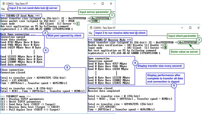
Figure 8‑3 Send data test by using non-jumbo frame
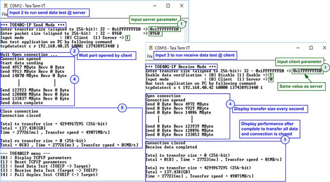
Figure 8‑4 Send data test by using jumbo frame
8.4 Receive Data Test (client to server)
To transfer data from client to server, select ‘3’ to run receive data test on server FPGA and select ‘2’ to run send data test on client FPGA. User inputs test parameters through Serial console. The sequence to run the test is shown as below.
1) On Serial console of server, input three parameters in receive data test.
a) Input transfer size: Unit of transfer size is byte. Valid value is 32 - 0x1F_FFFF_FFE0. The input must be aligned to 32. User selects to input as or hexadecimal unit. To input as hex value, user adds “0x” as a prefix.
b) Input data verification mode: Set ‘0’ to disable data verification or ‘1’ to enable data verification to verify data from FPGA running as client.
c) Input Mode: Mode of FPGA to transfer data. Input ‘1’ to set server mode.
2) If inputs are valid, “Wait Open connection …” will be displayed.
3) On Serial console of client, input three test parameters in send data test.
a) Input transfer size: Unit of transfer size is byte. Valid value is 32 - 0x1F_FFFF_FFE0. The input must be aligned to 32. User selects to input as decimal or hexadecimal unit. To input as hex value, user adds “0x” as a prefix. This value must be equal to transfer size on server FPGA.
b) Input packet size: Unit of packet size is byte. Valid value is 32 – 8960. The input must be aligned to 32. User selects to input as decimal or hexadecimal unit. To input as hex value, user adds “0x” as a prefix.
c) Input Mode: Mode of FPGA to transfer data. Input ‘0’ to set client mode.
If inputs are valid, the operation will start.
4) After running client, current transfer size is displayed on both Serial consoles every second.
5) “Connection closed” and “Received data completed” are displayed on Serial console of server after client completes to send all data and closes the connection. Total transfer size and performance are displayed on both Serial consoles.
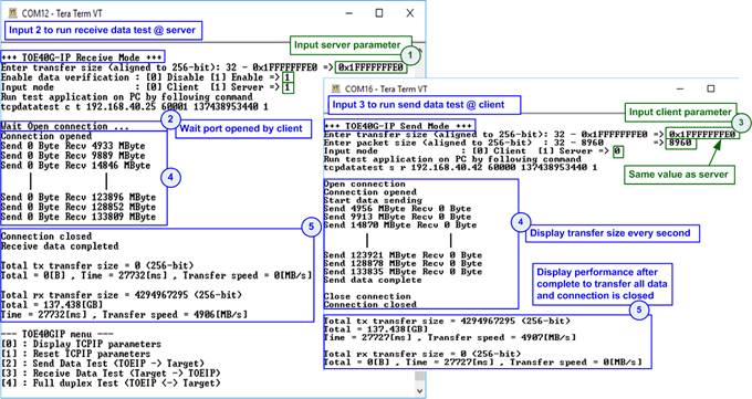
Figure 8‑5 Receive data test with data verification
8.5 Full duplex Test
Select ‘4’ to run full duplex test on server FPGA and client FPGA to transfer data in both directions at the same time. User inputs test parameters through Serial console. The sequence to run the test is shown as below.
1) On Serial console of server, input four parameters in full duplex test.
a) Input transfer size: Unit of transfer size is byte. Valid value is 32 - 0x1F_FFFF_FFE0. The input must be aligned to 32 and must match with transfer size in FPGA running as client. User selects to input as decimal or hexadecimal unit. To input as hex value, user adds “0x” as a prefix.
b) Input packet size: Unit of packet size is byte. Valid value is 32 – 8960. The input must be aligned to 32. User selects to input as decimal or hexadecimal unit. To input as hex value, user adds “0x” as a prefix.
c) Input data verification mode: Set ‘0’ to disable data verification or ‘1’ to enable data verification to verify data from FPGA running as client.
d) Input Mode: Mode of FPGA to transfer data. Input ‘1’ to set server mode.
2) If inputs are valid, “Wait open connection…” will be displayed.
3) On Serial console of client, input four test parameters in full duplex test.
a) Input transfer size: Unit of transfer size is byte. Valid value is 32 - 1F_FFFF_FFE0. The input must be aligned to 32 and must match with transfer size in FPGA running as server. User selects to input as decimal or hexadecimal unit. To input as hex value, user adds “0x” as a prefix.
b) Input packet size: Unit of packet size is byte. Valid value is 32 – 8960. The input must be aligned to 32. User selects to input as decimal or hexadecimal unit. To input as hex value, user adds “0x” as a prefix.
c) Input data verification mode: Set ‘0’ to disable data verification or ‘1’ to enable data verification to verify data from FPGA running as server.
d) Input Mode: Mode of FPGA to transfer data. Input ‘0’ to set client mode.
If inputs are valid, the operation will begin.
4) After running client, current transfer size is displayed on both Serial consoles every second.
5) “Send data complete” is displayed on Serial console of client after it completes to send and receive all data and closes the connection. Total transfer size and performance are displayed on both Serial consoles.
Step 4) – 5) run in forever loop until user cancels the operation. To cancel operation, press any keys on server Serial console and client Serial console.
Figure 8‑6 shows full duplex test. Left window is Serial console from FPGA running as server and right window is Serial console from FPGA running as client.
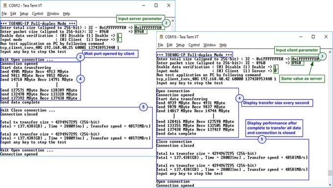
Figure 8‑6 Full duplex test with data verification
9 Revision History
|
Revision |
Date |
Description |
|
1.0 |
2-Oct-18 |
Initial version release |
|
1.1 |
27-Nov-18 |
Support KCU105 board |
|
1.2 |
6-Dec-18 |
Correct Figure 5-10 |