UDP10G IP loopback test instruction
Rev1.0 30-Jun-23
This document describes the instruction to run loopback demo on FPGA development board by using AB15-SFPFMC board. The demo is designed to run TenGEMAC IP loopback test for measuring the latency time and total run time. Two EMAC IPs are integrated in the system to compare the latency time between two IPs. First EMAC IP is DG TenGEMAC IP and another IP is Intel TenGEMAC IP. Other hardwares (UDP10G IP and PCS/PMA IP) to run with TenGEMAC IP are similar. User can set test parameters on FPGA board and monitor the hardware status on NiosII command shell.
1 Environment Setup
To perform UDP10G IP loopback demo, please prepare the following test environment, as shown in Figure 1‑1.
1) Cyclone10 GX FPGA development board
2) Two optical cables with 2x10 Gb SFP+ transceiver (10G BASE-R) for two loopback network connections.
3) micro USB cable for JTAG connection (FPGA programming and JTAG UART), connecting between FPGA board and PC.
4) AB15-SFPFMC, provided by Design Gateway.
5) QuartusII Programmer for programming FPGA and NiosII command shell, installed on PC

Figure 1‑1Test environment for the demo
2 Demo setup
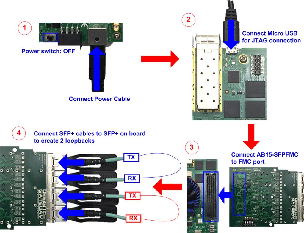
Figure 2‑1 FPGA board setup
1) Turn off power switch and connect power supply to FPGA board.
2) Connect FPGA board with PC by micro USB cable.
3) Connect AB15-SFPFMC to FMC connector on FPGA board
4) Insert SFP+ transceivers with optical cables to create two loopbacks as shown in Figure 2‑1.
5) Turn on power switch of FPGA board.
6) Open QuartusII Programmer to program FPGA through USB-1 by following steps.
a. Click “Hardware Setup…” to select USB-BlasterII[USB-1].
b. Click “Auto Detect” and select FPGA (10CX220YF780).
c. Select Cyclone10 device icon.
d. Click “Change File” button, select SOF file in pop-up window, and click “open” button.
e. Check “Program”.
f. Click “Start” button to program FPGA.
g. Wait until Progress status is successful.
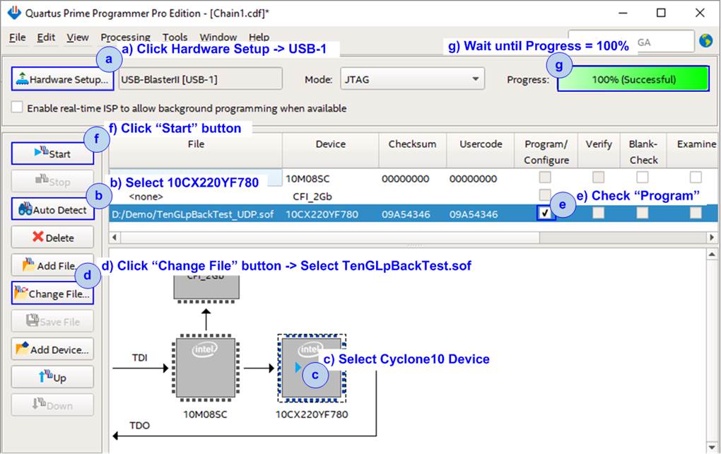
Figure 2‑2 FPGA Programmer
7) Open NiosII command shell.
a. Type “nios2-terminal”.
b. Default parameters are displayed on the console.
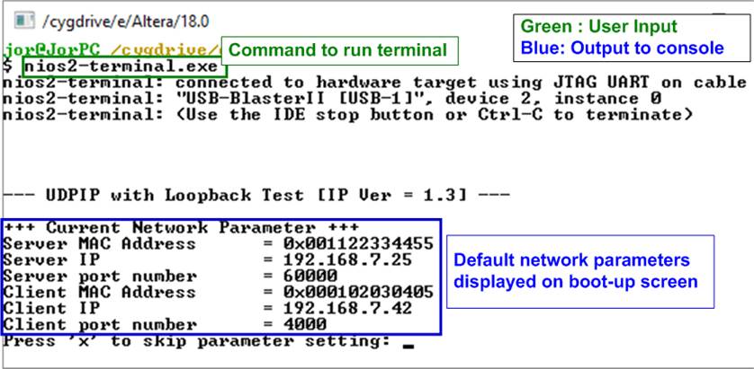
Figure 2‑3 NiosII command shell after boot-up
8) Enter ‘x’ to skip parameter setting. The default parameters are applied for system initialization, as shown in Figure 2‑4. If other keys are entered, the menu to change parameter will be displayed. The example of changing parameter is shown in topic 3.2 (Reset Network parameters).
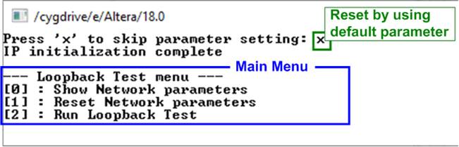
Figure 2‑4 Initialization complete
3 Test menu
3.1 Show Network parameters
Select ‘0’ to check current parameter in the demo. There are six parameters displayed on the console. In this demo, both loopbacks share the same server and client network parameters.
One loopback consists of two UDP10G IPs. The server network parameters are applied to one UDP10G IP which sends data while the client network parameters are applied to another UDP10G IP which receives data.
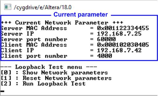
Figure 3‑1 Display current parameter result
1) Server MAC address: 48-bit hex value to be MAC address of server. Default value is 0x001122334455.
2) Server IP: IP address of server. Default value is 192.168.7.25.
3) Server port number: Port number of server. Default value is 60000.
4) Client MAC address: 48-bit hex value to be MAC address of client. Default value is 0x000102030405.
5) Client IP: IP address of Client. Default value is 192.168.7.42.
6) Client port number: Port number of client. Default value is 4000.
To change some parameters can be done by using menu [1] Reset Network parameters.
3.2 Reset Network parameters
Select ‘1’ to reset the IP or change IP parameters. This menu is used to change IP parameters or send reset to all UDP10G IP. After user selects this menu, the current parameters are displayed on the console. Enter ‘x’ to use same parameters and send reset to all UDP10G IPs. Other keys are entered to change some parameters and then reset UDP10G IPs.
There are six parameters to set in this menu. Each of parameters is verified by CPU. The parameters are updated to UDP10G IP when the input is valid. If the input is not valid, the value will not change. After user assigns all parameters, UDP10G IP is reset. The description of each parameter is shown in topic 3.1 (Show Network parameter) and the range of each parameter is described as follows.
1) Server MAC address: Input 12 digit of hex value. Add “0x” as a prefix to input as hex value.
2) Server IP address: A set of four decimal digits is separated by “.”. The valid range of each decimal digit is 0-255.
3) Server port number: Valid range is 0-65535.
4) Client MAC address: Input 12 digit of hex value. Add “0x” as a prefix to input as hex value.
5) Client IP address: A set of four decimal digits is separated by “.”. The valid range of each decimal digit is 0-255.
6) Client port number: Valid range is 0-65535.
After user assigns all parameters, new parameter set is displayed on the console. Next, reset signal is sent to the UDP10G IPs to load new parameter set to all UDP10G IPs in the design. Finally, “IP initialization complete” is shown after all UDP10G IPs finish initialization process, as shown in Figure 3‑2.

Figure 3‑2 Change Network parameters result
3.3 Run Loopback Test
Select ‘2’ to run the loopback test of both loopbacks on FPGA. User enters test parameters on FPGA through NiosII command shell. The sequence to run the test is shown as follows.
1) On NiosII command shell, enter three parameters under run loopback test menu.
a) Input transfer byte size: Unit of transfer size is byte. Valid value is 0x8 - 0xFFFFFFF8. The value must be aligned to 8. The input is decimal when only digit number is assigned. User can add “0x” as a prefix when the input is hexadecimal.
b) Input packet byte size: Unit of packet size is byte. Valid value is 8 – 8968. The value must be aligned to 8. The input is decimal when only digit number is assigned. User can add “0x” as a prefix when the input is hexadecimal.
c) Input number of loops: Valid value is 0x1 – 0xFFFFFFFF. Number of loops to repeat the test with the same inputs as a) and b). The input is decimal when only digit number is assigned. User can add “0x” as a prefix when the input is hexadecimal.
2) After all parameters are given and valid, both loopbacks start transferring data at the same time. Server UDP10G IP sends data to client UDP10G IP in the same loopback. All timers run to measure latency and usage time in the transfer process. During transferring data, the transmitted data size and the received data size are displayed on the console every second.
3) “Transfer data completed” is displayed on the console after all data are sent and received in the loopbacks. Finally, total transfer size, performance, and latency of both loopbacks are displayed as shown in Figure 3‑3.
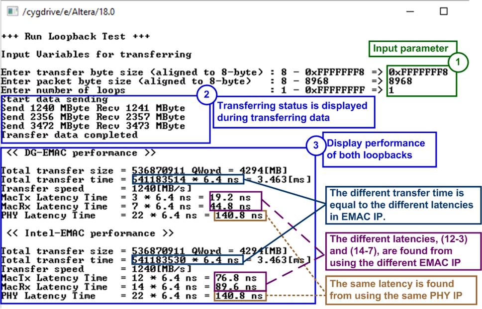
Figure 3‑3 Loopback test with maximum transfer size and packet size for 1 loop
There are six values displayed as the performance result in Figure 3‑3.
a) Total transfer size: Total received size which is sum of the size in each loop. The value is displayed in 64-bit (Qword) unit and B(Byte)/KB(KiloByte)/MB(MegaByte).
b) Total transfer time: Total run time displayed in clock cycle unit. One clock cycle is equal to 6.4 ns. Total time in s(second}/ms(millisecond)/us(microsecond) unit is displayed. The time duration is only measured when data is transferring in the loopback. The time using for other operations in CPU such as sending command process and calculation process is not included.
c) Transfer speed: Performance which is calculated from total transfer size and total transfer time. The unit of transfer speed is B/s (byte per second), KB/s (KiloByte per second), or MB/s (MegaByte per second).
d) MacTx Latency Time: The latency time of Tx data path within TenGEMAC IP in clock cycle unit (6.4 ns per 1 clock cycle) and nanosecond unit.
e) MacRx Latency Time: The latency time of Rx data path within TenGEMAC IP in clock cycle unit (6.4 ns per 1 clock cycle) and nanosecond unit.
f) PHY Latency Time: The latency time of physical layer and external hardware for loopback connection in clock cycle unit (6.4 ns per 1 clock cycle) and nanosecond unit.
The results from two loopback designs are displayed for performance comparison. The different module is EMAC IP, so Tx latency time and Rx latency time within EMAC is different. But PHY latency time is same.
As shown in Figure 3‑3,
- MacTx latency time of DG EMAC is less than Intel EMAC about 9 clock cycles.
- MacRx latency time of DG EMAC is less than Intel EMAC about 7 clock cycles.
- So, total transfer time of DG EMAC is less than Intel EMAC about 16 clock cycles (9 + 7).
The different latency time in EMAC IP has much effect when transfer size per loop is less.
As shown in Figure 3‑4, the test result by using minimum size is displayed. In this case, total time of DG EMAC is less than total time of Intel EMAC about 16% ( (100-84)/100 ).
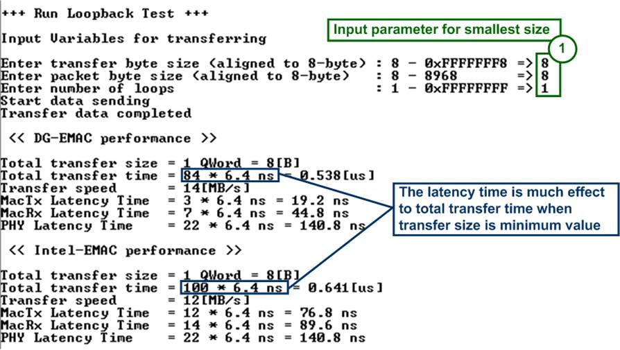
Figure 3‑4 Loopback test with minimum transfer size and packet size for 1 loop
The different time usage is much when running small packet size for many loops. Figure 3‑5 shows the test result when the size is 8 byte and runs for 1,000,000 loops.
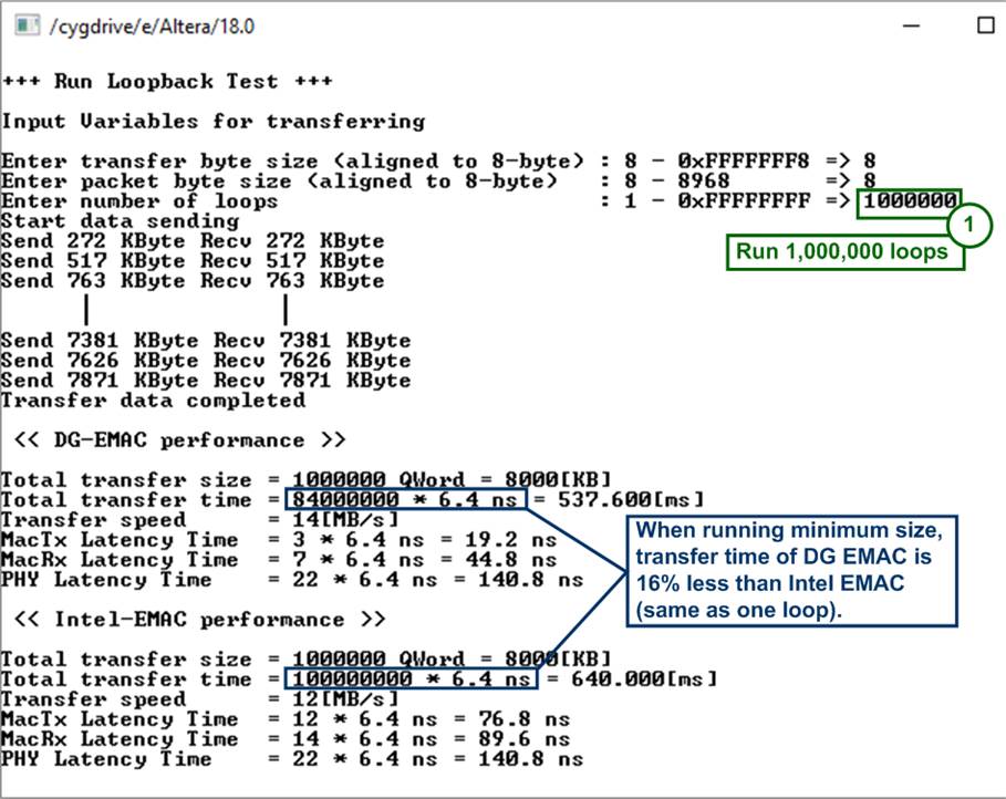
Figure 3‑5 Loopback test with minimum transfer size and packet size for 1,000,000 loops
If the input is invalid, “Out-of-range input” will be displayed and the operation will be cancelled, as shown in Figure 3‑6-Figure 3‑8.
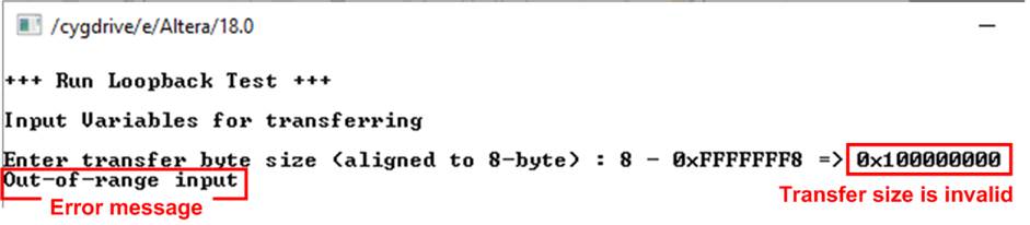
Figure 3‑6 Error from invalid transfer size
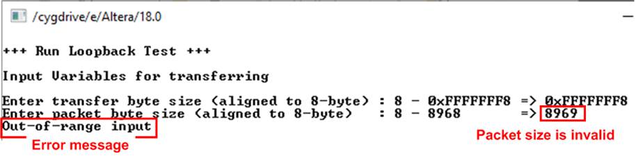
Figure 3‑7 Error from invalid packet size
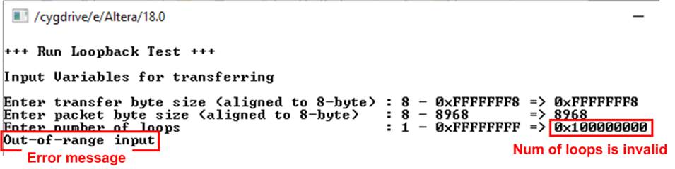
Figure 3‑8 Error from invalid number of loops
4 Revision History
|
Revision |
Date |
Description |
|
1.0 |
15-Aug-19 |
Initial version release |