tCAM IP Search Replace Demo Instruction
Rev1.01 2-Jun-2023
4 tCAMIP Search Replace demo software
4.1 Demo software interface description
4.2 Search and Replace sample table
This document describes the instruction to demonstrate the operation of tCAMIP on Arria10SoC development board. This demonstration shows search/replace text function by using tCAMIP on A10SoC board via 10 Gigabit Ethernet communication.
1 Environment Setup
To operate tCAMIP Search Replace demo, please prepare following test environment.
1) FPGA development boards (Arria10SoC development board)
2) Test PC with 10 Gigabit Ethernet connector.
3) Micro USB cable for JTAG connection between FPGA development board and Test PC
4) 10Gb Ethernet cable.
5) Quartus Prime for programming FPGA, installed on Test PC
6) File “tCAMIPSearchReplacePack.zip” that included Test Application named “tCAMIP Search Replace” and configuration file named “tCAMIPRef_time_limited.sof”.
(to download this file, please visit our web site at www.design-gateway.com)
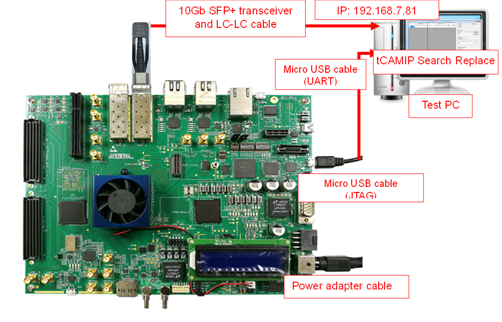
Figure 1‑1 tCAMIP Reference Design demo on Arria10SoC board
2 PC Setup
Before running demo, please check the network setting on PC. Ethernet setting is shown as follows.
2.1 IP Setting

Figure 2‑1 Setting IP address for PC
1) Open Local Area Connection Properties of 10-Gb connection, as shown in the left window of Figure 2‑1.
2) Select “TCP/IPv4” and then click Properties.
3) Set IP address = 192.168.7.81 and Subnet mask = 255.255.255.0, as shown in the right window of Figure 2‑1.
2.2 Speed and Frame Setting

Figure 2‑2 Set frame size = jumbo frame
1) On Local Area Connection Properties window, click “Configure” as shown in Figure 2‑2.
2) On Advanced Tab, select “Jumbo Packet”. Set Value to “9014 Bytes” for Jumbo Frame support or set value to “Disabled” for non-Jumbo Frame support, as shown in the bottom window of Figure 2‑2.
3) On Link Speed, select “10 Gbps Full Duplex” for running 10-Gigabit transfer test, as shown in Figure 2‑3.

Figure 2‑3 Set link speed = 10 Gbps
4) On PROSet Advanced Tab, select “Performance Options” and click “Properties” button.
5) Set “Interrupt Moderation Rate” = OFF.

Figure 2‑4 Interrupt Moderation Rate
6) Select “Low Latency Interrupts” and click “Properties” button.
7) On “Low Latency Interrupts” window, select “Use Low Latency Interrupts” and click “OK” button.
8) Click “OK” button to save and exit all setting windows.

Figure 2‑5 Use Low Latency Interrupts
2.3 Power Option Setting
1) Open Control Panel and select Power Options as shown in the left window of Figure 2‑6.
2) Change setting to High Performance as shown in the right window of Figure 2‑6.
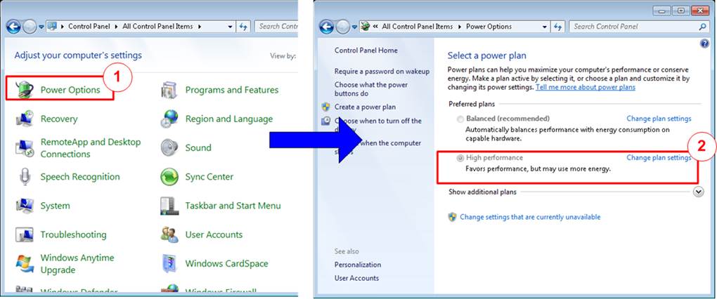
Figure 2‑6 Power options
3 FPGA board setup
1) Make sure power switch is off and connect power supply to FPGA development board.
2) Connect USB cable between FPGA board and PC via micro USB
3) Connect 10Gb Ethernet cable (10 Gb SFP+ DAC (Length<1m), AOC or SFP+ transceiver with LC-LC cable) between FPGA board and PC.
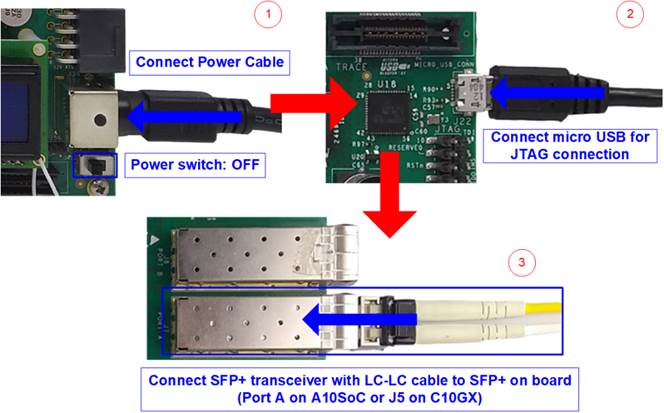
Figure 3‑1 Power, Ethernet, and micro USB cable connection
5) For Arria10 SoC board, set programmable clock to 322.265625 MHz by using “Clock Control” application as following step.
a) Open “Clock Controller” application.
b) Select Si5338 tab (U50) and set CLK3 frequency = 322.265625 MHz.
c) Click “Set” button and wait until the application is active again.
d) Close Clock controller application.

Figure 3‑2 Reference clock programming
6) Open QuartusII Programmer to program FPGA through USB-1 by following step.
e) Click “Hardware Setup…” to select USB-BlasterII [USB-1].
f) Click “Auto Detect” and select FPGA device. (10AS066N3).
g) Select FPGA device icon.
h) Click “Change File” button, select SOF file in pop-up window, and click “open” button
i) Check “program”
j) Click “Start” button to program FPGA and wait until Progress status is equal to 100%
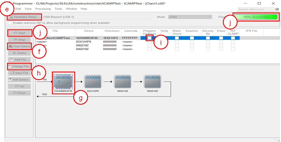
Figure 3‑3 FPGA Programmer
7) When configuration is completed, Quartus will show popup message of OpenCore Plus as shown in Figure 3‑4. Please do not press cancel button, because NiosII in tCAMIP will stop running.
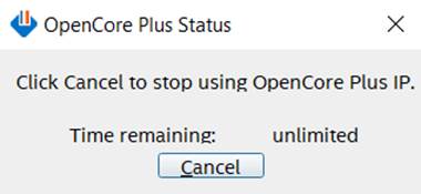
Figure 3‑4 OpenCore Plus Status
8) When configuration is completed, user can check status LEDs on board as Figure 3‑5
o LED0 is turned on when hardware reset switch “S10” is push.
o LED1 is turned on when TOE10GIP is ready for data transfer.
o LED2 is turned on when tCAMIP is initialized successfully.
o LED3 is turned on when software open connection to A10SoC board.
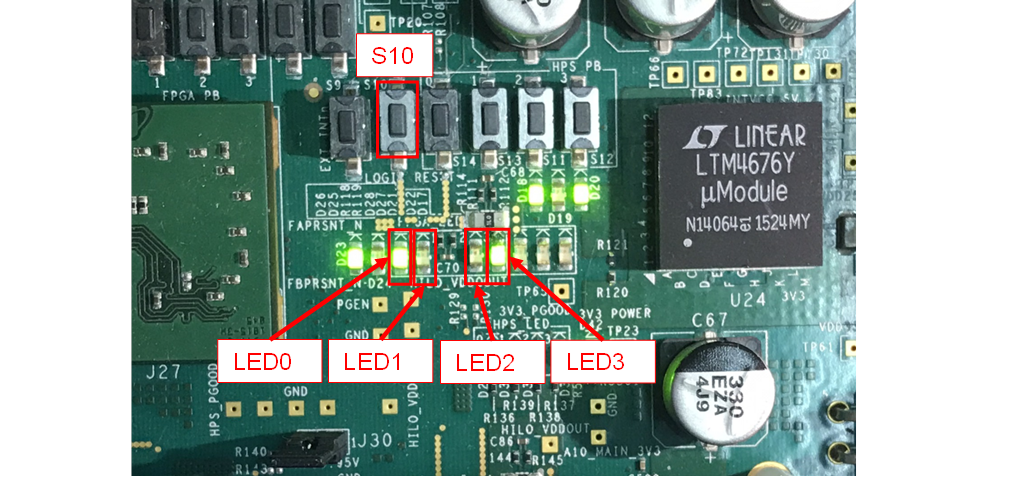
Figure 3‑5 LED[3:0] status on board
4 tCAMIP Search Replace demo software
tCAMIP Search Replace demo software is designed to do search/replace text function by using space bar to be delimiter. tCAMIP Replace button is search and replace text by using tCAMIP on A10SoC board via 10 Gigabit Ethernet.
4.1 Demo software interface description
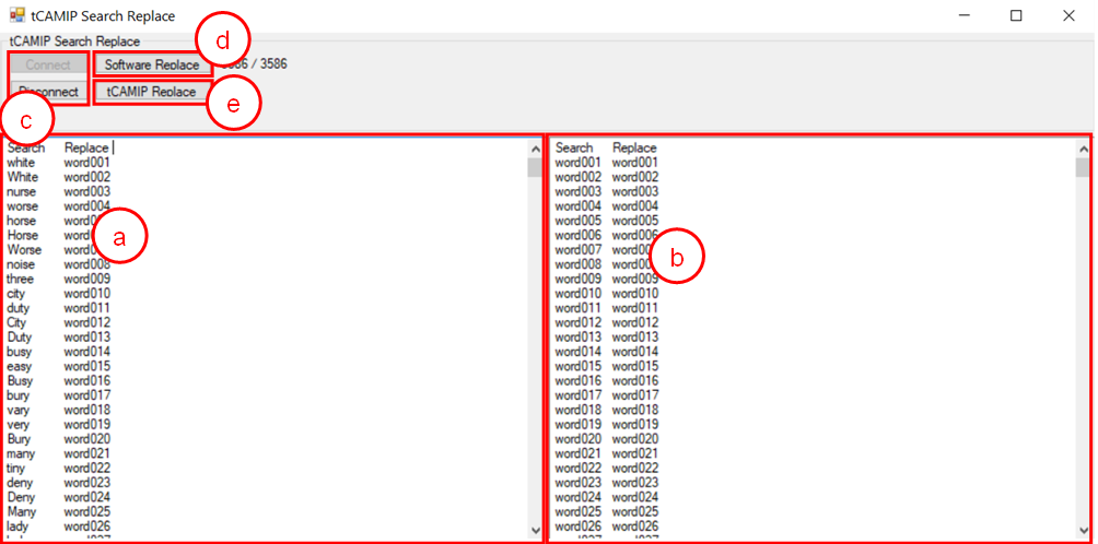
Figure 4‑1 Software interface
Figure 4‑1 shows tCAMIP Search Replace user interface and the description is shown as below.
a) Input source text for search. (“input.txt” is sample text)
b) Output result text after replace.
c) Connect/Disconnect with A10SoC board via 10 Gigabit Ethernet.
d) Software Replace, this button will search and replace text with software.
e) tCAMIP Replace, this button will be sent source text via 10 Gigabit Ethernet to search and replace text by using tCAMIP.
4.2 Search and Replace sample table
Please refer sample table of search and replace word in file “SampleTable.txt”.
4.3 Sample text
“SampleText.txt” is prepared for sample of input source text. Figure 4‑2 shows sample result using “SampleText.txt”
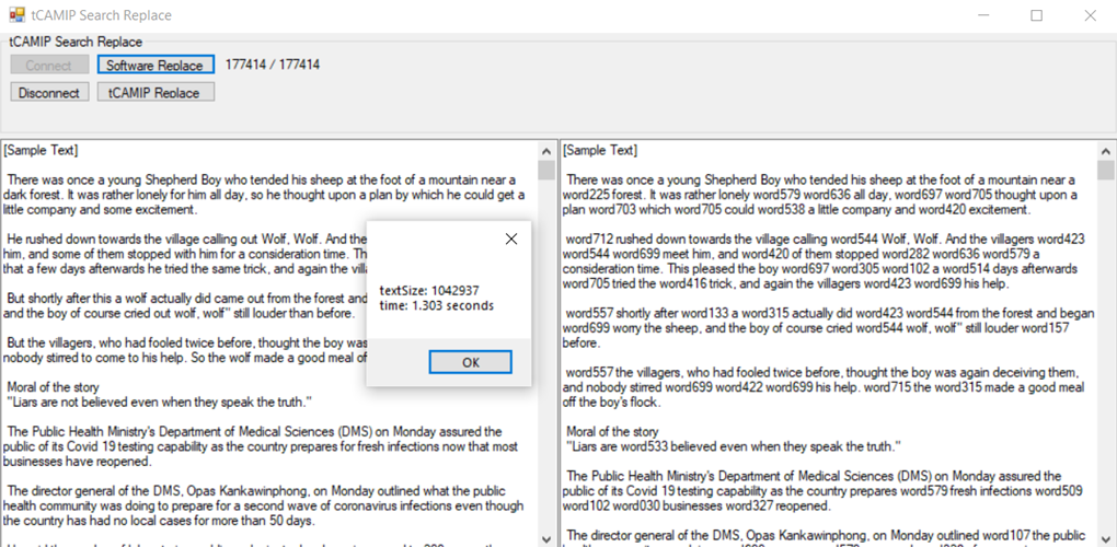
Figure 4‑2 Sample result using “SampleText.txt”
5 Revision History
|
Revision |
Date |
Description |
|
1.01 |
5-Mar-2021 |
Revise
|
|
1.00 |
25-Aug-2020 |
Initial version release
|