tCAMIP reference design by Search Replace function
Rev1.00 1-Sep-2023
2.1.4 tCAMIP searching process
1 Introduction
This document describes the detail of tCAMIP reference design. In this reference design, tCAMIP are used for search/replace function. More details of the hardware design are described as follows.
2 Hardware overview
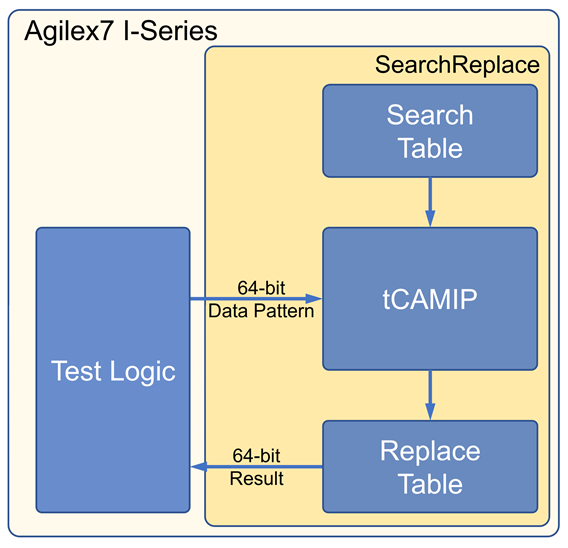
Figure 2‑1 Reference design block diagram
In this test environment, the SearchReplace module comprises a tCAMIP along with two simple dual-port RAMs functioning as a search table and a replace table, respectively. The system incorporates Test Logic to control the operation of the entire system. LEDs are employed to indicate the working status.
2.1 Search Replace module
Search Replace module is designed to search 64-bit dataIn in Search Table. When dataIn is matched in Search Table, dataOut is assigned with replace word from Replace Table. But if dataIn is not matched in Search Table (resultData=0), the dataIn is assigned to dataOut instead.
2.1.1 Search Table
Search Table is dual port RAM, 8K address x 9-bit width. This table is assigned to be rule table for tCAMIP.
Port A is reserved for future used.
Port B is connected with tCAMIP as shown in Table 2‑1.
ruleCount(3) is designed to generate 1 clock cycle pulse delay from ruleRdReq signal and is assigned to be ruleRdValid signal. Figure 2‑2 show timing diagram of ruleRdValid generation.
Table 2‑1 Port B signal mapping of search table
|
Search Table signals |
Dir |
tCAMIP signals |
|
src_wren_b |
<= |
'0' |
|
src_data_b |
<= |
(others => '0') |
|
src_address_b |
<= |
ruleAddr |
|
q_b |
=> |
ruleData |
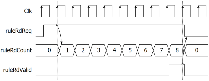
Figure 2‑2 Timing diagram of ruleRdValid generation
Each 8-byte ASCII code of search word is assigned as 8 x 9-bit rule. The “don’t care” byte is assigned as [x], 0x100 value. Table 2‑2 shows sample conversion from search word to rule table. Search Table is initialed values with file “search.mif”.
Table 2‑2 Sample of search word conversion to rule table memory
|
Rule No. |
Search word |
Address |
A+0 |
A+1 |
A+2 |
A+3 |
A+4 |
A+5 |
A+6 |
A+7 |
|
0001 |
white |
0000 |
‘w’, 077 |
‘h’, 068 |
‘i’, 069 |
‘t’, 074 |
‘e’, 065 |
‘ ’, 020 |
[x], 100 |
[x], 100 |
|
0002 |
White |
0008 |
057 |
068 |
069 |
074 |
065 |
020 |
100 |
100 |
|
0003 |
nurse |
0010 |
06E |
075 |
072 |
073 |
065 |
020 |
100 |
100 |
|
0004 |
worse |
0018 |
077 |
06F |
072 |
073 |
065 |
020 |
100 |
100 |
|
0005 |
horse |
0020 |
068 |
06F |
072 |
073 |
065 |
020 |
100 |
100 |
|
0006 |
Horse |
0028 |
048 |
06F |
072 |
073 |
065 |
020 |
100 |
100 |
|
0007 |
Worse |
0030 |
057 |
06F |
072 |
073 |
065 |
020 |
100 |
100 |
|
0008 |
noise |
0038 |
06E |
06F |
069 |
073 |
065 |
020 |
100 |
100 |
|
0009 |
three |
0040 |
074 |
068 |
072 |
065 |
065 |
020 |
100 |
100 |
|
000A |
city |
0048 |
063 |
069 |
074 |
079 |
020 |
100 |
100 |
100 |
|
000B |
duty |
0050 |
064 |
075 |
074 |
079 |
020 |
100 |
100 |
100 |
|
000C |
City |
0058 |
043 |
069 |
074 |
079 |
020 |
100 |
100 |
100 |
|
000D |
Duty |
0060 |
044 |
075 |
074 |
079 |
020 |
100 |
100 |
100 |
|
000E |
busy |
0068 |
062 |
075 |
073 |
079 |
020 |
100 |
100 |
100 |
|
000F |
easy |
0070 |
065 |
061 |
073 |
079 |
020 |
100 |
100 |
100 |
|
0010 |
Busy |
0078 |
042 |
075 |
073 |
079 |
020 |
100 |
100 |
100 |
|
0011 |
bury |
0080 |
062 |
075 |
072 |
079 |
020 |
100 |
100 |
100 |
|
… |
|
|
|
|
|
|
|
|
|
|
Note: All numbers are hex number.
2.1.2 Initial State Machine
This reference design is provided simple state machine to initialize tCAMIP. Figure 2‑3 show timing diagram of Initial State Machine to generate ruleInit signal and check ruleBusy and ruleStatusCode signals. Operation of initialization is described as below.
· When RstB is active (‘0’), rState is set to stIdle.
· When RstB is released (‘1’), rState is changed to stInitStart.
· At stInitStart, rState is changed to stWaitReady when ruleBusy is active from tCAMIP.
· At stWaitReady, rState is changed to stInitCompleted when ruleBusy is released to zero and ruleStatusCode is 0001b (initial completed).
o In case that ruleBusy is released to zero but ruleStatusCode is not 0001b, it means tCAMIP initialization is not success. rState is changed to stIdle for restart initial process again.
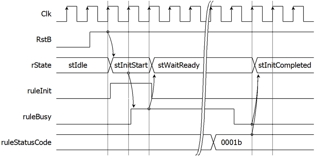
Figure 2‑3 Timing diagram of Initial State Machine
2.1.3 Replace Table
Replace Table is dual port RAM, 1K address x 64-bit width. This table is assigned with replace word. The relation between search word, replace word and memory data is shown as in Table 2‑4. Replace Table is initialed values with file “replace.mif”. For further details and all related parameters, please refer to the file "SampleTable.txt".
According to resultData from tCAMIP is mapping with Rule No., then address of replace word can be calculated by resultData minus 1 (rep_address_b <= resultData – 1). The detailed of signals assignment is shown as below.
Port A is reserved for user logics.
Port B is connected with signals as shown in Table 2‑3.
Table 2‑3 Port B signal mapping of replace table
|
Replace Table signals |
Dir |
tCAMIP signals |
|
rep_wren_b |
<= |
'0' |
|
rep_data_b |
<= |
(others => '0') |
|
rep_address_b |
<= |
resultData - 1 |
|
rep_q_b |
=> |
rep_q_b |
Table 2‑4 Sample of search word conversion to rule table memory
|
Rule No. |
Search word |
Replace word |
Address |
Replace word (hex) |
|
0001 |
white |
word001 |
0000 |
2031303064726F77 |
|
0002 |
White |
word002 |
0001 |
2032303064726F77 |
|
0003 |
nurse |
word003 |
0002 |
2033303064726F77 |
|
0004 |
worse |
word004 |
0003 |
2034303064726F77 |
|
0005 |
horse |
word005 |
0004 |
2035303064726F77 |
|
0006 |
Horse |
word006 |
0005 |
2036303064726F77 |
|
0007 |
Worse |
word007 |
0006 |
2037303064726F77 |
|
0008 |
noise |
word008 |
0007 |
2038303064726F77 |
|
0009 |
three |
word009 |
0008 |
2039303064726F77 |
|
000A |
city |
word010 |
0009 |
2030313064726F77 |
|
000B |
duty |
word011 |
000A |
2031313064726F77 |
|
000C |
City |
word012 |
000B |
2032313064726F77 |
|
000D |
Duty |
word013 |
000C |
2033313064726F77 |
|
000E |
busy |
word014 |
000D |
2034313064726F77 |
|
000F |
easy |
word015 |
000E |
2035313064726F77 |
|
0010 |
Busy |
word016 |
000F |
2036313064726F77 |
|
… |
|
|
|
|
2.1.4 tCAMIP searching process
Figure 2‑4 shows timing diagram of searching data path. After tCAMIP initialization is completed by initial process on topic 2.1.2, In every clock cycle, dataIn will be searching by tCAMIP and set resultData as matched Rule No. by latency 7 clock cycles. rep_address_b (resultData – 1) from tCAMIP is used for address of Replace Table, then rep_q_b is out from Replace Table after 2 clock cycles because Replace Table memory is generated with both registers of input address port and output port. rSearchMatch(0) is set to ‘1’ when resultData from tCAMIP is zero (not match). Then rSearchMatch(1) is one clock cycle delay from rSearchMatch(0). To control timing of input dataIn and rep_q_b in the same clock cycle, dataIn8 is 9 clock cycles delay from dataIn signals, then dataIn8 and rep_q_b is valid in the same clock cycle. rLongWord is set to be ‘1’ when previous cycle of dataIn8[63:56] (last byte of word) is 0x20 (space bar character). Then dataOut is register output multiplexer that is assigned with rep_q_b when rLongWord=’0’ and rSearchMatch(1)=’1’, else is assigned with dataIn8.
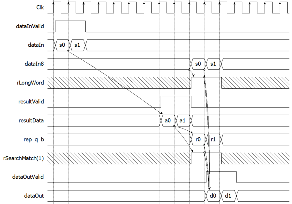
Figure 2‑4 Timing diagram of searching data path
3 Test Logic
For testing, the Search Replace module uses Test Logic to generate dataInValid and dataIn for use as input data to Search Replace module, and validate the output of the Search Replace module. Test Logic will display the operation status through LED. The definition of LED is shown in the Table 3‑1.
Table 3‑1 LED Definition
|
GPIO LED |
ON |
OFF |
|
0 |
Normal operation |
Reset is active |
|
1 |
Ready |
Not Ready |
|
2 |
Error detected |
Normal operation |
|
3 |
dataInValid=‘1’ |
dataInValid=‘0’ |
Figure 3‑1 Example test logic operation timing diagram, after tCAMIP initialization is completed by initial process on topic 2.1.2. Ready signal is asserted to ‘1’, then rCnt[15:0] will be started to count. When rCnt[8:4] is 0x01, dataInValid is asserted to ‘1’ for 16 clock cycles, and dataIn[63:0] is valid by selecting from rPattern data. Then dataOutValid will be active ? clock cycles after dataInValid, So we prepare rResult data pattern and result[63:0] for compare with dataOut[63:0] to show the correct operation of tCAM-IP.
However in case of something wrong, such as dataOut is not same as rResult data pattern, the rError signal is asserted to ‘1’ and will be active LED[2] to show error status.
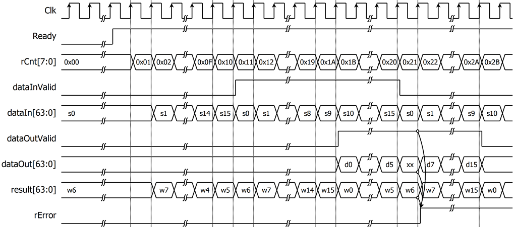
Figure 3‑2 Example test logic operation when dataOut not match result
4 Revision History
|
Revision |
Date |
Description |
|
1.00 |
21-Jul-2023 |
Initial version release |