tCAM IP Search Replace Demo Instruction
Rev1.00 1-Sep-2023
2 FPGA development board setup
3.2 SignalTap trigger condition
3.2.1 To see Input key and Search result signals
This document describes the instruction to demonstrate the operation of tCAMIP on Agilex7 I-series development kit. This demonstration shows search/replace text function by using tCAMIP. User is also able to use SignalTap to see the operation of provided signals in FPGA.
1 Environment Setup
To operate tCAMIP demo, please prepare following test environment.
1) FPGA development boards (Agilex7 I-series development kit)
2) Test PC.
3) Micro USB cable for JTAG connection between FPGA development board and Test PC
4) Quartus programmer for programming FPGA, installed on Test PC
5) SOF file named “tCAMIP.sof” (To download these files, please visit our web site at www.design-gateway.com)
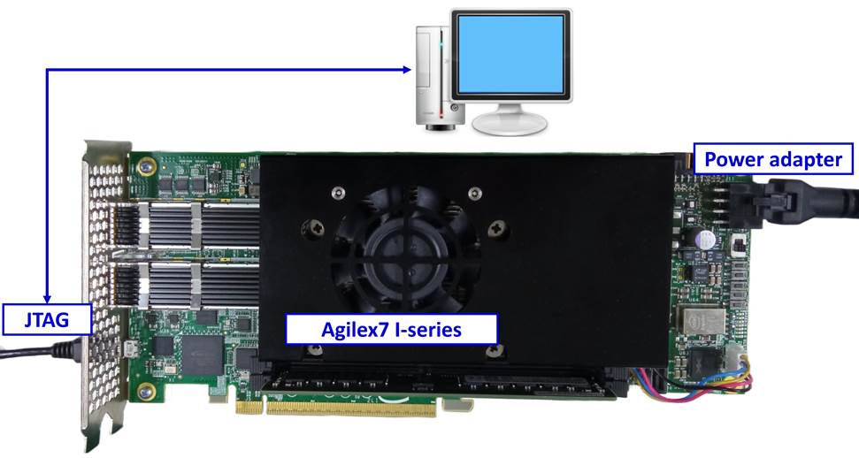
Figure 1‑1 tCAMIP demo on Agilex7 I-series board
2 FPGA development board setup
1) Make sure power switch is off and connect power supply to FPGA development board.
2) Connect USB cables between FPGA board and PC via micro-USB ports.
3) Turn on power switch for FPGA board.
4) Open Quartus Programmer to program FPGA through USB-1 by following step.
i) Click “Hardware Setup…” to select
AGI FPGA Development Kit [USB-1] for Agilex7 I-series
ii) Click “Auto Detect” and select FPGA number.
iii) Select FPGA device icon (Agilex or A10SoC).
iv) Click “Change File” button, select SOF file in pop-up window and click “open” button.
v) Check “program”.
vi) Click “Start” button to program FPGA.
vii) Wait until Progress status is equal to 100%.
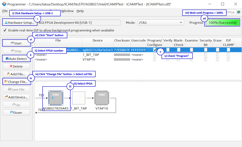
Figure 2‑1 FPGA Programmer for Agilex
5) When configuration is completed, user can check status LEDs on board as Figure 2‑2.
- LED0 is show reset status, This LED is on when the reset signal is not active.
- LED1 is show “Ready” status of Search Replace Module.
- LED2 is show Error status, This LED is on when an error is detected.
- LED3 is always blink to show dataInValid is working.
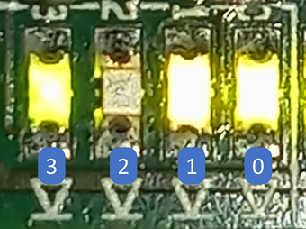
Figure 2‑2 LED[3:0] status on board
3 SignalTap Logic Analyzer
Block diagram of the tCAMIP demonstration is shown as in Figure 3‑1. SignalTap is prepared to show waveform of input and output of tCAMIP in FPGA. User can set trigger condition to show the desired waveform.
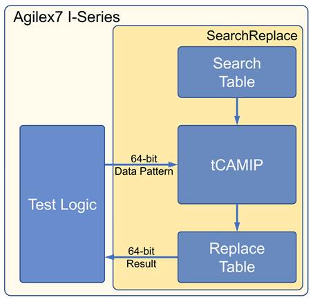
Figure 3‑1 tCAMIP Demo block diagram
3.1 SignalTap operations
Step to use Signal Tap Logic Analyzer is as follows.
a) Click File -> Open …, then select file type to Signal Tap Logic Analyzer Files (*.stp)
b) Select “stp1.stp”, then click Open button as shown in Figure 3‑2
c) As in Figure 3‑3, select Hardware to AGI FPGA Development Kit.
d) Setup trigger condition to specify signals behavior. Sample of trigger condition and result is shown as in topic 3.2
e) Click “Run Analysis” button, wait to capture signals from tCAMIP.
f) The result will be shown, when do SignalTap detect signals same as trigger condition.
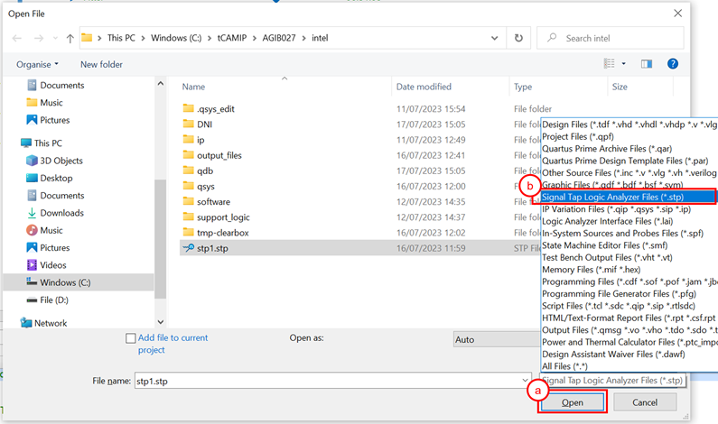
Figure 3‑2 Open file “stp1.stp”
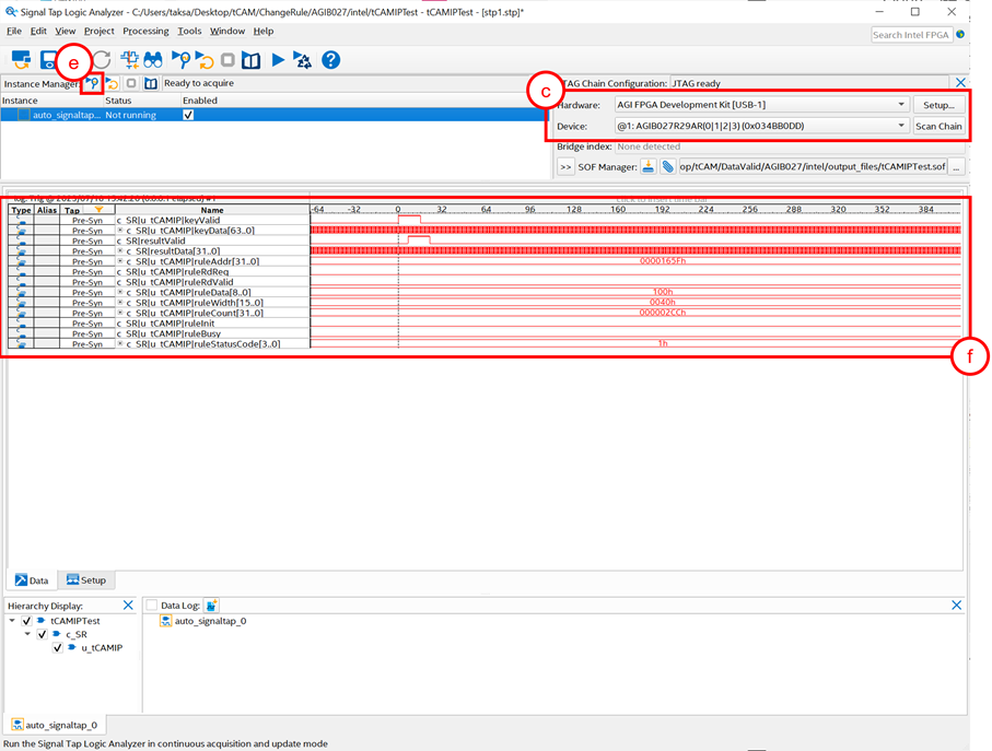
Figure 3‑3 SignalTap II Logic Analyzer
3.2 SignalTap trigger condition
On demo running, user is able to use SignalTap to setup trigger condition and check the signal waveform after trigger is detected. The provided SignalTap signals can be triggered based on Input keys & search result signal.
3.2.1 To see Input key and Search result signals
Figure 3‑4 show trigger condition and Figure 3‑5 show sample result from SignalTap when user search key data.
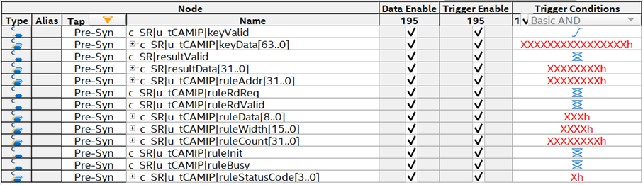
Figure 3‑4 Trigger setup for input key and searching result
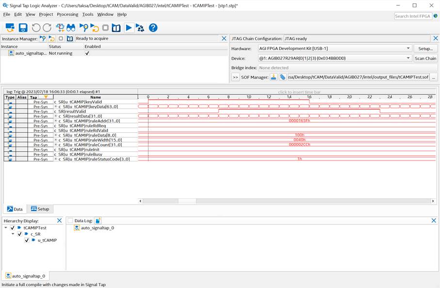
Figure 3‑5 Sample result for input key and searching result
4 Revision History
|
Revision |
Date |
Description |
|
1.00 |
21-Jun-2023 |
Initial version release |