UDP Packet Switching Demo Instruction
2.3 Network properties settings
3 UDP Packet Switching Demo setup
5.5 Clear All Access List Entries
6 Software UDP Client and Server for Test
7 UDP Packet Switching Behavior Demonstration
7.1 Add Access List Entry and Switch to Destination Mode.
7.2 View All Entries in Access List
7.3 Open UDP Server to Listen on Port 4433
8 Demonstration of UDP Packet Filtering
8.1 Add Access List Entry and Switch to Destination Mode
8.2 View all Entries in Access List
8.3 Open UDP Server to Listen on Port 4433
All configurations for this demo can be easily managed through the serial console interface. This instruction will guide you through setting up the test environment, running the demo, and interpreting the results.
1 Environment Setup
To operate tCAM-IP demo, please prepare following test environment.
1) FPGA development board (KCU116 development board)
2) Test PC with 10 Gigabit Ethernet card.
3) Micro USB cable for JTAG connection between FPGA board and Test PC.
4) Micro USB cable for UART connection between FPGA board and Test PC.
5) 10Gb Ethernet cable (SFP+ to SFP+).
6) Vivado tool for programming FPGA installed on Test PC.
7) Serial console software such as TeraTerm installed on PC. The setting on the console is Baudrate=115,200, Data=8-bit, Non-parity and Stop=1.
8) Demo configuration file (To download this file, please visit our web site at www.design-gateway.com).
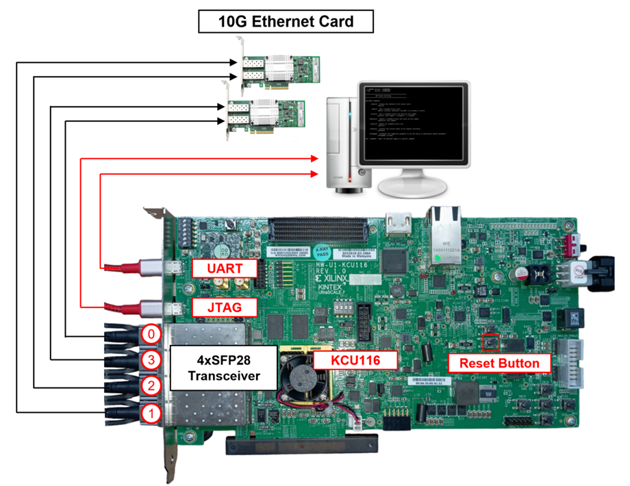
Figure 1 tCAM-IP demo on KCU116 board
2 PC Setup
Before running demo, please check the network setting on PC. Ethernet setting is shown as follows.
2.1 IP Setting
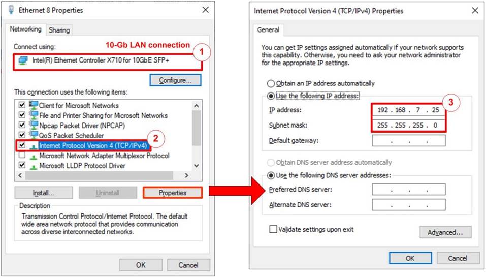
Figure 2 Setting IP address for PC
1) Open Local Area Connection Properties of 10 Gb connection, as shown in the left window of Figure 2.
2) Select “TCP/IPv4” and then click Properties.
3) Set the IP addresses to 192.168.7.25, 192.168.7.20, 192.168.7.30, and 192.168.7.35 with a subnet mask of 255.255.255.0, as shown in the right window of Figure 2.
2.2 Speed and duplex settings
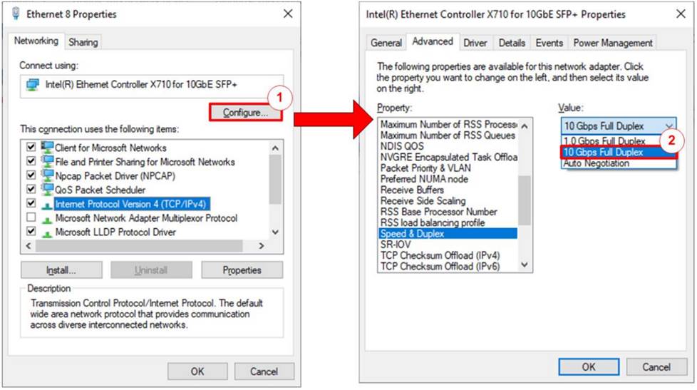
Figure 3 Set Link Speed = 10 Gbps
1) On Local Area Connection Properties window, click “Configure”, as shown in Figure 3.
2) On Advanced Tab, select “Speed and Duplex”. Set the value to “10 Gbps Full Duplex” for running 10 Gigabit transfer test, as shown inFigure 3.
2.3 Network properties settings
Some of network parameter settings may affect network performance. The example of network properties setting is as follows.
1) On “Interrupt Moderation” window, select “Disabled” to disable interrupt moderation which would minimize the latency during transferring data, as shown in Figure 4
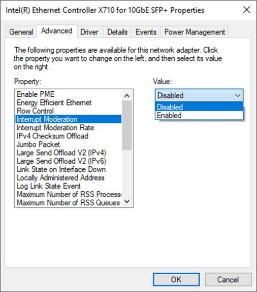
Figure 4 Interrupt Moderation
2) On “Interrupt Moderation Rate” window, set the value to “OFF”, as shown in Figure 5.
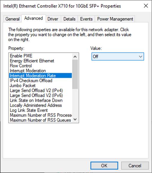
Figure 5 Interrupt Moderation Rate
3) On “Jumbo packet” window, set the value to “9014 Bytes”, as shown in Figure 6.
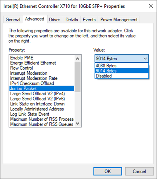
Figure 6 Jumbo packet
4) On “Receive Buffers” window, set the value to the maximum value, as shown in Figure 7.
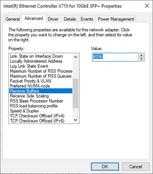
Figure 7 Receive Buffers
5) On “Transmit Buffers” window, set the value to the maximum value, as shown in Figure 8.
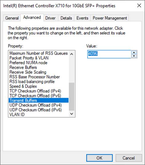
Figure 8 Transmit buffers
3 UDP Packet Switching Demo setup
1) Make sure the power switch is off and connect the power supply to KCU116 development board.
2) Connect 10Gb SFP+ cable from KCU116 board to PC.
i) SFP0 to NIC with IP 192.168.7.25
ii) SFP1 to NIC with IP 192.168.7.20
iii) SFP2 to NIC with IP 192.168.7.35
iv) SFP3 to NIC with IP 192.168.7.30
3) Connect USB cable between PC to JTAG micro USB port.
4) Power on the system.
5) Open Vivado Hardware Manager to program FPGA by following steps.
i) Click open Hardware Manager.
ii) Click “Auto Connect” to connect with the board.
iii) Select FPGA device to program bit file.
iv) Click Program device.
v) Click “…” to select program bit file.
vi) Click Program button to start FPGA Programming.
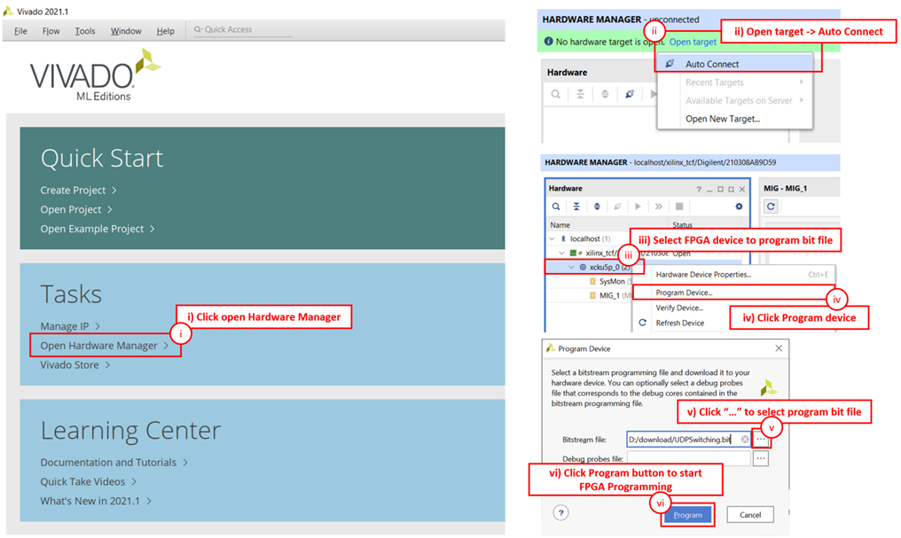
Figure 9 Program Device
4 Serial Console
Users can configure various parameters and manage the UDP packet switching application directly through the serial console. The available commands allow users to control access list, filter UDP packets, and monitor network status. The UDP packet switching commands and their usages are displayed as shown in Figure 10. Detailed information about each command is described in topic 5.
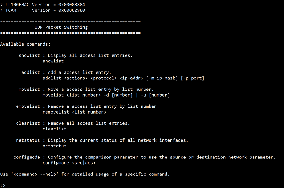
Figure 10 Serial console
5 Command detail
5.1 Show Access List
command> showlist
This command displays all access list entries, including detailed information, for UDP packet switching. The entries are prioritized based on their list numbers, with lower numbers taking precedence.
5.2 Add Access List Entry
command> addlist <action> <protocol> <ip-addr> [-m ip-mask] [-p port]
This command adds a new entry to the access list. Users must specify the active channels in binary format in the action field, protocol (TCP, UDP, ICMP), IP address in ip-addr, optional wildcard mask for the IP address with -m, and port number (TCP, UDP) with -p if required.
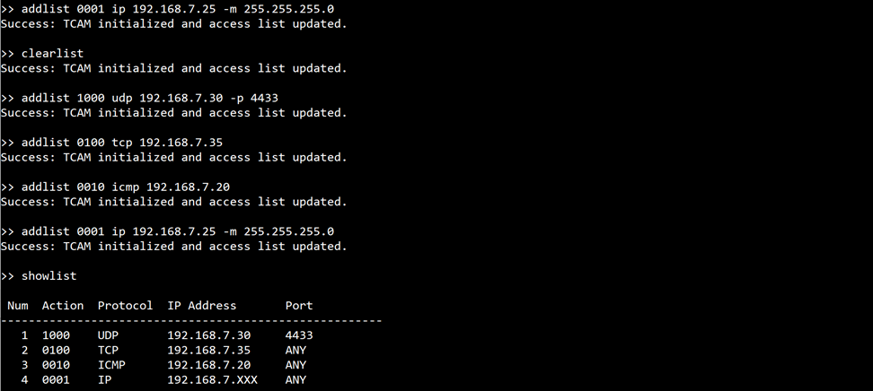
Figure 11 Example of the showlist and addlist command usage
5.3 Move Access List Entry
command> movelist <list number> -d [number] | -u [number]
This command moves an access list entry up or down in the list. Use the -d option to move down and -u to move up by the specified number of positions.
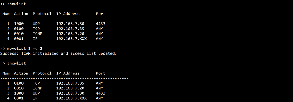
Figure 12 Example of the movelist command usage
5.4 Remove Access List Entry
command> removelist <list number>
This command removes a specific access list entry based on its list number.
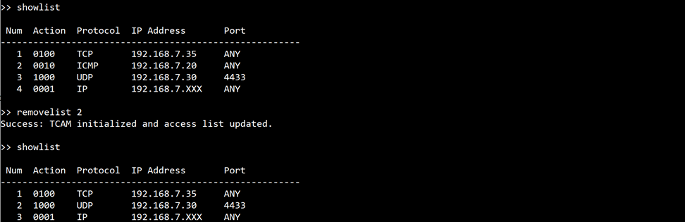
Figure 13 Example of the removelist command usage
5.5 Clear All Access List Entries
command> clearlist
This command removes all entries from the access list, clearing all previously configured rules from the system.
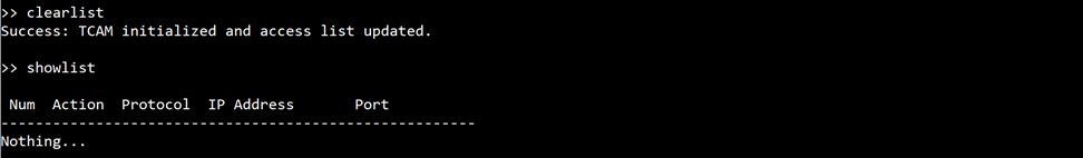
Figure 14 Example of the clearlist command usage
5.6 Show Network Status
command> netstatus
This command displays the current status of all ethernet interfaces card.
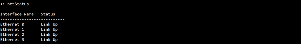
Figure 15 Example of the netstatus command usage
5.7 Configure Comparison Mode
command> configmode <src|des>
This command configures the comparison mode to use either the source (src) or destination (des) network parameter for filtering and switching UDP packets.
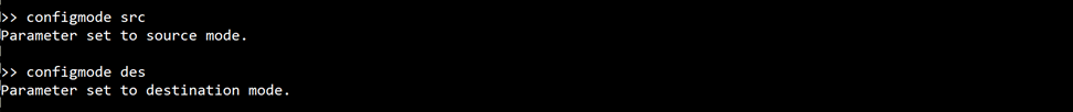
Figure 16 Example of the configmode command usage
6 Software UDP Client and Server for Test
This section details the software components used for testing UDP packet transmission and reception, implemented in Python. The demo utilizes two distinct programs: a UDP client and a UDP server.
6.1 UDP Client
The UDP client is designed to send UDP packets to a specified IP address and port. It can be configured with several options, including the delay between packets, the number of packets to send, and the size of each packet. The client is executed with the following command-line arguments:
l Client IP : The IP address of the client (e.g., 192.168.7.25).
l - d <delay> : The delay between packets in seconds (default: 0).
l - n <loop> : The number of packets to send (default: 100).
l - s <size> : The size data to extend (default: 0).
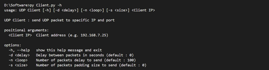
Figure 17 Example of the UDP client displaying help options
Additional Client Configuration
In addition to the above options, the UDP client allows users to specify multiple server targets. Users can configure the "server" variable in the “Client.py” file to include a list of server IP addresses and ports, enabling the client to send packets to multiple servers. Users can modify the server IP addresses and ports, and add or remove server targets as needed.
For example, the “server” variable can be set as follows:
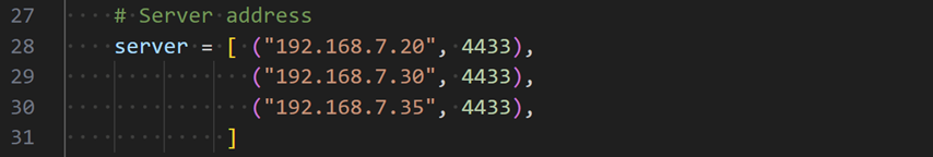
Figure 18 Example of the configmode command usage
6.2 UDP Server
The UDP server listens for incoming UDP packets on all IP addresses and a specified port. It is configured with the following command-line argument:
l Server IP:Port : The server's IP address and port (e.g., 192.168.7.25:4433).
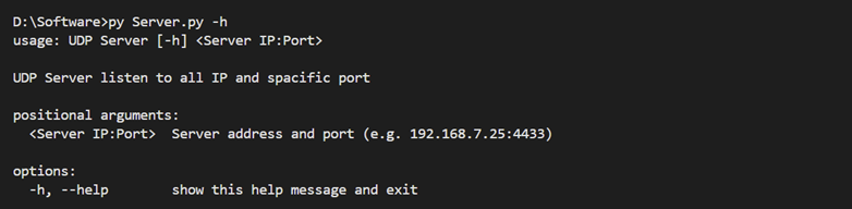
Figure 19 Example of the UDP server displaying help options
The client and server are both implemented in Python,
providing a straightforward and flexible setup for demonstrating UDP packet
switching.
7 UDP Packet Switching Behavior Demonstration
In this demonstration, the UDP packet switching behavior will be observed after configuring the access list and switching to destination mode. The UDP client will send packets through the interface card with IP “192.168.7.25”, and the system will route these packets to the correct destination servers based on the access list.
7.1 Add Access List Entry and Switch to Destination Mode
First, define the access list to route packets to specific servers, with each entry corresponding to a different server IP address and port. After configuring the access list, switch the system to destination mode to enable packet routing based on the destination IP addresses.
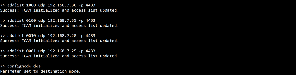
Figure 20 Example of adding access list entry and switching to destination mode
7.2 View All Entries in Access List
After defining the lists, verify the configuration using the showlist command.
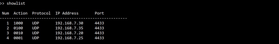
Figure 21 Example of displaying all configured access list
7.3 Open UDP Server to Listen on Port 4433
To receive the UDP packets, the server needs to run by excusing “server.py” with ip address and port of ethernet interface.
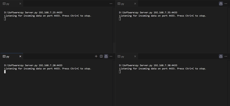
Figure 22 Example of opening UDP servers listening on port 4433 for all four channels
7.4 Packet Transmission
Configure the UDP client to send packets to the following servers. Open the “Client.py” script and update the “server” variable as shown below.
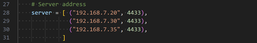
Figure 23 Example of updating the “server” variable in UDP client
Run the UDP client with the following command to start sending packets through the interface with IP 192.168.7.25.

Figure 24 Example of command to start UDP client
7.5 Result
From the demonstration, it can be observed that the UDP client sends data to UDP servers at 192.168.7.30, 192.168.7.35, and 192.168.7.20. Each UDP server successfully receives and displays the data. Figure 26 show the Wireshark capture, showing that each ethernet interface card only receives packets that match its own IP address. This confirms that the packet switching system correctly routes the UDP packets according to the configured access list.
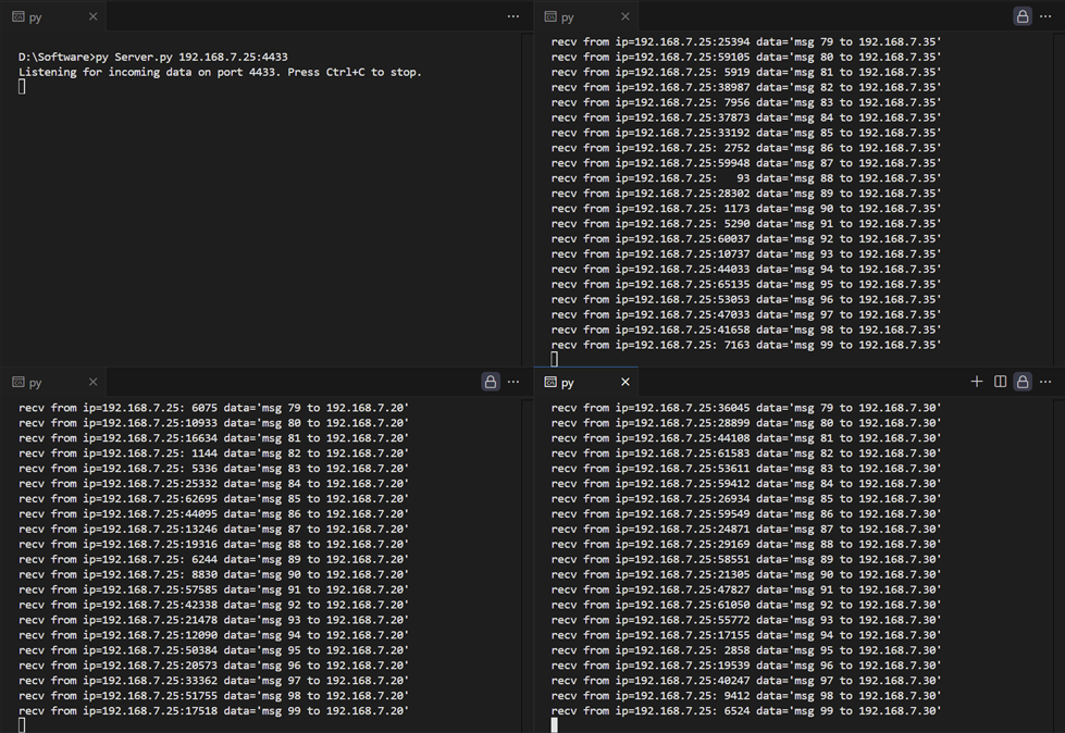
Figure 25 Example of UDP servers receiving data from UDP client
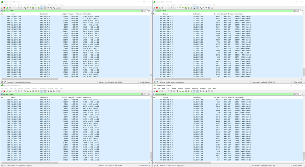
Figure 26 Wireshark capture of UDP packet transmission
8 Demonstration of UDP Packet Filtering
In this demonstration showcase how to implement UDP packet filtering within the system. The focus will be on configuring the access list to control the flow of UDP packets based on their destination IP address. It will show how certain packets can be selectively blocked from reaching specific servers, while allowing others to be routed to their designated destinations.
8.1 Add Access List Entry and Switch to Destination Mode
First, configure access list to control the routing of UDP packets to specific servers. Set up rules to ensure that UDP packets destined for 192.168.7.30 on port 4433 are not forwarded to any port, effectively filtering out these packets from being sent to any interface card. On the other hand, packets intended for 192.168.7.20, 192.168.7.25, and 192.168.7.35 on port 4433 will be directed to the designated interfaces as specified in our access list configuration. Then switch the system to destination mode, allowing the packet routing to be based on the destination IP addresses.
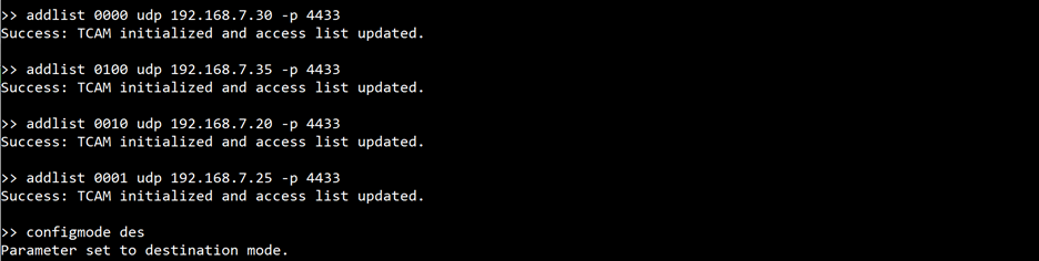
Figure 27 Example of adding access list and switching to destination mode
8.2 View all Entries in Access List
After defining the lists, verify the configuration using the showlist command.
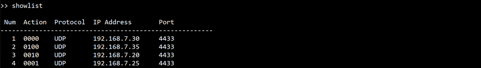
Figure 28 Example of displaying all configured access list
8.3 Open UDP Server to Listen on Port 4433
To receive the UDP packets, the server needs to run by excusing “server.py” with ip address and port of ethernet interface.
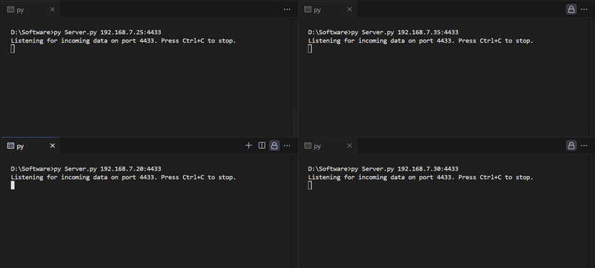
Figure 29 Example of opening UDP servers listening on port 4433 for all four channels
8.4 Packet Transmission
Configure the UDP client to send packets to the following servers. Open the “Client.py” script and update the “server” variable as shown below.

Figure 30 Example of updating the “server” variable in UDP client
Run the UDP client with the following command to start sending packets through the interface with IP 192.168.7.25.

Figure 31 Example of command to start UDP client
8.5 Result
From the demonstration, it can be observed that the UDP client sends data to UDP servers at 192.168.7.30, 192.168.7.35, and 192.168.7.20. Each UDP server successfully receives and displays the data, except for the server at 192.168.7.30, which does not receive any packets. Figure 33 shows the Wireshark capture, where the interface 192.168.7.25 is seen sending data to 192.168.7.20, 192.168.7.30, and 192.168.7.35. The other interface card only receives packets that match its own IP address, except for interface 192.168.7.30 having no packets received. This indicates that the system filtered out packets intended for IP 192.168.7.30.
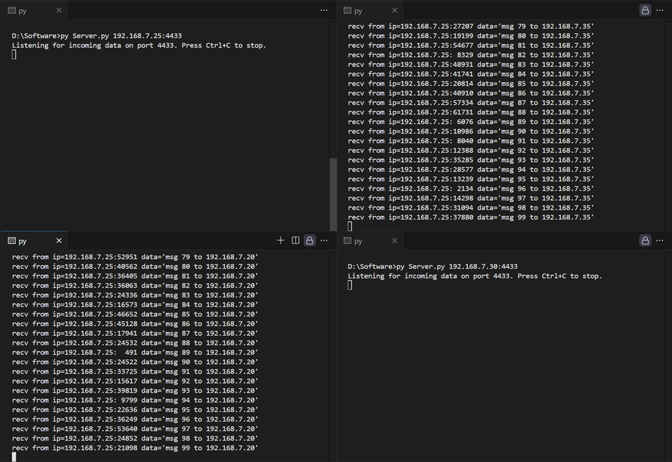
Figure 32 Example of UDP servers receiving data from UDP client
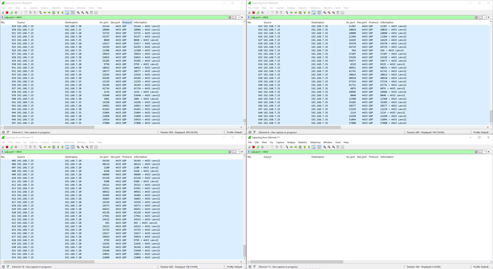
Figure 33 Wireshark capture of UDP packet transmission
9 Revision History
|
Revision |
Date (D-M-Y) |
Description |
|
1.01 |
14-Oct-24 |
Update table of contents. |
|
1.00 |
2-Oct-24 |
Initial version release |