UDP Packet Switching Reference Design
2.5 Xilinx Transceiver (PMA for 10GBASE-R)
3.5 Clear All Access List Entries
1 Introduction
This document outlines the details of the UDP Packet Switching Reference Design. In this design, the tCAM-IP serves as the core decision-making component, with a focus on processing packets similarly to Access Control Lists (ACLs). Users can configure access lists by entering supported commands via a serial console. Further details on the hardware design and CPU firmware are provided in the sections below.
2 Hardware Overview
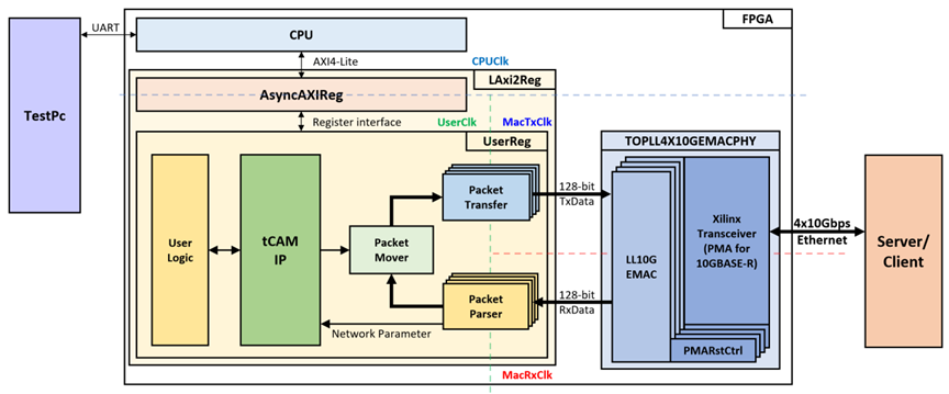
Figure 1 UDP Packet Switching reference design block diagram
In this test environment, two devices are used to transfer data over four 10G Ethernet ports. The FPGA functions as a switch, while the target device, which can be either a PC or another FPGA, is responsible for sending and receiving data, as shown in Figure 1. The tCAM-IP is integrated into the UserReg module, which is connected to the CPU via AsyncAXIReg using a register interface. The CPU connects to AsyncAXIReg through the AXI4-Lite interface.
The PacketParser module analyzes network parameters from ethernet packets received from the EMAC, forwarding them to the tCAM-IP. The tCAM-IP processes the network parameters according to the access list configured by the user. Following this, the PacketMover module directs the ethernet packets from PacketParser to PacketTransfer as defined by the tCAM-IP. The PacketTransfer module then sends the data back to the EMAC.
There are four system clocks in this reference design: CPUClk, UserClk, MacTxClk, and MacRxClk. The CPUClk is used for interfacing with the CPU through the AXI4-Lite bus. The UserClk domain is where the tCAM-IP operates and connects with user logic. The MacTxClk is synchronized with the Tx interface of the EMAC, while the MacRxClk is synchronized with the Rx interface of the EMAC. The details of each module are described as follows.
2.1 LAxi2Reg
The LAxi2Reg module is connected to the CPU through the AXI4-Lite bus. The hardware registers are mapped to the CPU’s memory address, as shown in Table 1. This module is responsible for the control and status registers that the CPU accesses via LAxi2Reg.
LAxi2Reg is composed of two main components: AsyncAxiReg and UserReg. The AsyncAxiReg converts the AXI4-Lite signals into a simple register interface with a 32-bit data bus size (similar to that of AXI4-Lite). As depicted in Figure 1, two clock domains are applied in this block: CpuClk, used for interfacing with the CPU via the AXI4-Lite bus, and UserClk, which serves as the user clock domain for tCAM-IP. The AsyncAxiReg includes asynchronous circuitry to manage the interaction between the CpuClk and UserClk domains.
The UserReg module contains the register file, which stores parameters and status signals related to test logic, including user logic and the tCAM-IP. Further details on AsyncAxiReg and UserReg are provided in the following sections.
2.2 AsyncAxiReg
This module is designed to convert the AXI4-Lite signal interface into a register interface, while enabling communication between two clock domains.
For writing to a register, the RegWrEn signal is asserted to '1' along with valid signals for RegAddr (the register address in 32-bit units), RegWrData (the write data for the register), and RegWrByteEn (the byte enable for this access: bit[0] controls write enable for RegWrData[7:0], bit[1] for RegWrData[15:8], and so on, with bit[3] controlling RegWrData[31:24]).
To read from a register, the AsyncAxiReg module asserts RegRdReq to '1' with a valid value for RegAddr (the register address in 32-bit units). The module then waits for the RegRdValid signal to be asserted to '1', at which point the read data is received through the RegRdData signal within the same clock cycle.
The register interface address is shared for both write and read transactions, meaning that a user cannot perform read and write operations on the same register simultaneously. The timing diagram for the register interface is shown in Figure 2.
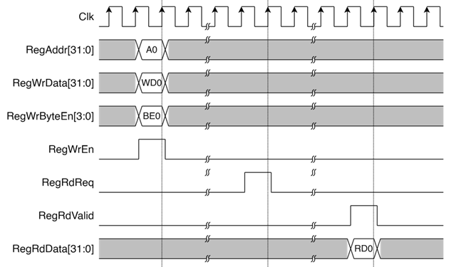
Figure 2 Register interface timing diagram
2.3 UserReg
For register file, UserReg is designed to write/read registers, control and check alert of the tCAM-IP corresponding with write register access or read register request from AsyncAvlReg module. The memory map inside UserReg module is shown in Table 1.
Table 1 Register map Definition of UDP Packet Switching
|
Address |
Register Name |
Rd/Wr |
Description |
|
0x0000 |
TCAM_RSTB_REG |
Wr |
[0] - Reset signal active low (rTCAMRstB). |
|
0x0004 |
TCAM_VERSION_REG |
Rd |
[31:0] - tCAM-IP version (IPversion[31:0]). |
|
0x0008 |
TCAM_STATUS_REG |
Rd |
[3:0] - tCAM-IP status code (IPruleStatusCode[3:0]) |
|
0x000C |
TCAM_START_REG |
Rd |
[0] - tCAM-IP initial operations busy status (IPruleBusy). |
|
Wr |
[0] - tCAM-IP initial start flag (rTCAMInitStart). |
||
|
0x0010 |
TCAM_RULEWIDTH_REG |
Wr |
[15:0] - The width of the rule in bit unit (rTCAMRuleWidth[15:0]). |
|
0x0014 |
TCAM_RULECOUNT_REG |
Wr |
[31:0] -
Number of rules to initialize tCAM-IP |
|
0x0100 |
USER_PARSER_MODE_REG |
Wr |
[3:0] - Network parser mode (rParserMode[3:0]). |
|
0x0400 |
USER_EMAC_LINKUP_REG |
Rd |
[3:0] -
Linkup status of LL10GEMAC |
|
0x0404 |
USER_EMAC_VERSION_REG |
Rd |
[31:0] - LL10GEMAC IP Version (EMacIPVersion). |
|
0x0408 |
USER_EMAC_RESET_REG |
Wr |
[0] - Reset signal for EMAC, active high (rEmacRst). |
|
0x4000 |
TCAM_RULE_BASE_ADDR |
Rd/Wr |
Base address for tCAM-IP rule configuration. |
|
0x8000 |
USER_MATCH_BASE_ADDR |
Rd/Wr |
Base address for user rule match table. |
2.3.1 PacketParser Module
The PacketParser module receives ethernet packets from the EMAC using a data stream interface. It stores the data in an internal buffer and analyzes network parameters from the ethernet packet. Users can access the analyzed network parameters through a FIFO interface.
As shown in Figure 3, the reception of a packet begins when the EMacRxValid signal is asserted, indicating valid data on EMacRxData[31:0]. The EMacRxByteEn[3:0] signal specifies which bytes within EMacRxData[31:0] are valid, while EMacRxEOP signal is asserted to ‘1’ at the end of the packet. In case of errors during reception, EMacRxError is asserted to '1' at the end of the packet, leading to the packet being discarded. The reception of data (D0 to D72) occurs when EMacRxValid is asserted.

Figure 3 Example of PacketParser receives packets from MAC Interface timing diagram
After the ethernet packet has been analyzed by the PacketParser module, it updates the network parameters. As show in Figure 4, when AFWFTMetaEmpty is ‘0’, network parameter data is available for use. To read the data, the user sets AFWFTMetaRdEn to '1', enabling the reading of AFWFTMetaOut[71:0], valid on the same clock cycle. The output data is structured as follows:
l AFWFTMetaOut[71:60] : Ethernet packet length (in 32-bit words).
l AFWFTMetaOut[59:56] : Ethernet type (e.g., “0001” for IPv4, “0010” for ARP).
l AFWFTMetaOut[55:48] : IP protocol (e.g., “0x11” for UDP, “0x06” for TCP).
l AFWFTMetaOut[47:16] : IP address for Ethernet type IPv4.
l AFWFTMetaOut[15:0] : Port for UDP or TCP protocols.
Additionally, when AFWFTDataEmpty is ‘0’, ethernet packet data is ready for access. The user sets AFWFTDataRdEn to '1' to read AFWFTDataOut[191:0], valid on the same clock cycle. To flush the current ethernet packet, the user must write the length of the packet (in 32-bit words) into AFWFTDataFlushCount[11:0], and AFWFTDataFlush is set to '1' to discard it.
The UserMode signal is used to determine whether the PacketParser analyzes ethernet packets based on source or destination network parameters. Specifically:
l UserMode[0] : Indicates whether source or destination UDP/TCP port to be processed.
l UserMode[1] : Indicates whether source or destination IPv4 addresses to be processed.
l UserMode[3:2] : Reserved.
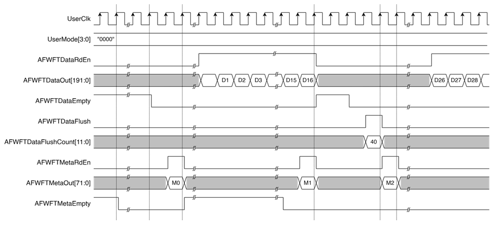
Figure 4 Example of accessing data from the PacketParser module timing diagram
2.3.2 PacketTransfer Module
The PacketTransfer module is responsible for receiving ethernet packets from the user, storing them in an internal buffer via a FIFO interface, and then transmitting the data to EMAC using a Data Stream interface.
Figure 5 shows the process of sending data to the PacketTransfer module. When the user wants to transmit data, they set AFWFTDataWrEn=‘1’, and the data in AFWFTDataIn[191:0] is validated and sent to the PacketTransfer module. If the buffer exceeds 75% capacity, AFWFTDataAFull will be asserted to ‘1’, indicating the user should stop sending data. Users must monitor this signal to avoid overflow. After writing the ethernet packet, the user writes the packet length (in 32-bit words) to AFWFTMetaIn[15:0] and sets AFWFTMetaWrEn=‘1’ to confirm it to the PacketTransfer module. Similar to data, AFWFTMetaAFull will indicate when the buffer is over 75% full.
Figure 6 shows an example of packet transmission. EMacTxValid is set to '1' along with valid values of EMacTxData, EMacTxEOP, and EMacTxByteEn. Transmission pauses when EMacTxReady is de-asserted to '0' and resumes when it is asserted again. EMacTxByteEn[3:0] indicates which bytes within EMacTxData[31:0] are valid, such as EMacTxByteEn[0] for EMacTxData[7:0] and EMacTxByteEn[1] for EMacTxData[15:8]. EMacTxEOP is asserted to signal the end of the packet.
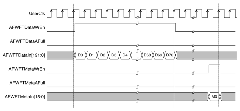
Figure 5 Example of transfer packet to PacketTransfer module timing diagram
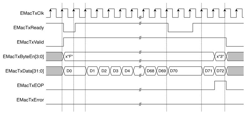
Figure 6 Example of PacketTransfer transfer packet to MAC Interface timing diagram
2.3.3 tCAM-IP Rule Initialize
In the reference design, the tCAM-IP analyzes network parameters to determine if they match any entries in the access list and identifies which list entry corresponds to the packet. Whenever the access list is modified, users must reinitialize the rules for the tCAM-IP. The width of the rule can be set by writing to the TCAM_RULEWIDTH_REG, which maps to the signal rTCAMRuleWidth[15:0]. Additionally, users can specify the number of rules by writing to the TCAM_RULECOUNT_REG, which maps to rTCAMRuleCount[31:0]. To begin the rule initialization process, the user writes to the TCAM_START_REG, where the signal rTCAMInitStart is set to 1 for one clock cycle.
While the tCAM-IP is initializing the rules, it reads data from the Rule Table by sending IPruleAddr[31:0] along with IPruleRdReq=’1’. In this design, the Rule Table is implemented as dual-port RAM. Port A is available for users to read and write rules, while Port B is dedicated to tCAM-IP for reading. The read process from Port B has a latency of 1 clock cycle, and the signal rTCAMRuleReadValid=‘1’ confirms that the data retrieved from the Rule Table (via RamRdDataA[8:0]) is valid.
Users can confirm that the tCAM-IP has completed the rule initialization by checking if IPruleBusy=‘0’, which can be read from TCAM_START_REG. Once the tCAM-IP has successfully initialized the rules, users should verify that IPruleStatusCode[3:0]=“0001”, indicating that the rule initialization has been successfully completed and the tCAM-IP is ready for use. This status can be read from TCAM_STATUS_REG.
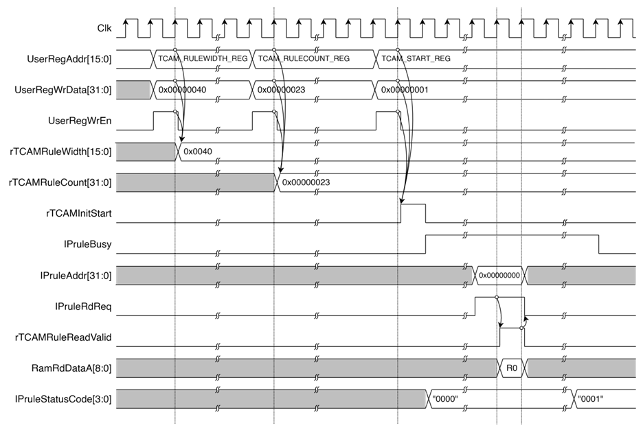
Figure 7 Example timing diagram for tCAM-IP Rule initialization
2.3.4 tCAM-IP Key Search
In the reference design, the tCAM-IP analyzes network parameters from the PacketParser module. Since the design utilizes four Ethernet interfaces, four instances of the PacketParser module are required. After the tCAM-IP rule initialization is complete and the PacketMover module is not almost full (i.e., wDMAQueueAFull!=‘1’), if some PacketParser modules are not empty (i.e., wFWFTMetaEmpty[3:0]!=0), the system will sequentially read available data from the non-empty PacketParser modules. It reads from one module per clock cycle by setting rReadFWFTMetaRdEn[3:0] to match the module being read.
The system processes the modules in a round-robin fashion, starting from the lowest index (0 -> 1 -> 2 -> 3). If a module is empty, it skips to the next. The values of rReadFWFTMetaRdEn[3:0] are cycled through as 0001, 0010, 0100, 1000, and then 0000 when no data is available. The system ensures that no module is read twice within the same clock cycle. The network parameters from the PacketParser modules are available on the signal wFWFTMetaOut[3:0][71:0].
Once the network parameters are received from the PacketParser modules, a key is generated for tCAM-IP lookup. This module uses only 60-bit LSB of wFWFTMetaOut at the corresponding channel i (wFWFTMetaOut[i][59:0]) to derive key. The key is stored in rTCAMKeyData[63:0]. The data is validated by setting rTCAMKeyValid=‘1’. When tCAM-IP completes the lookup, IPresultValid is set to ‘1’ and provides the rule index in IPresultValid[31:0]. If the network parameters do not match any rule, IPresultValid[31:0] will be set to ‘0’.
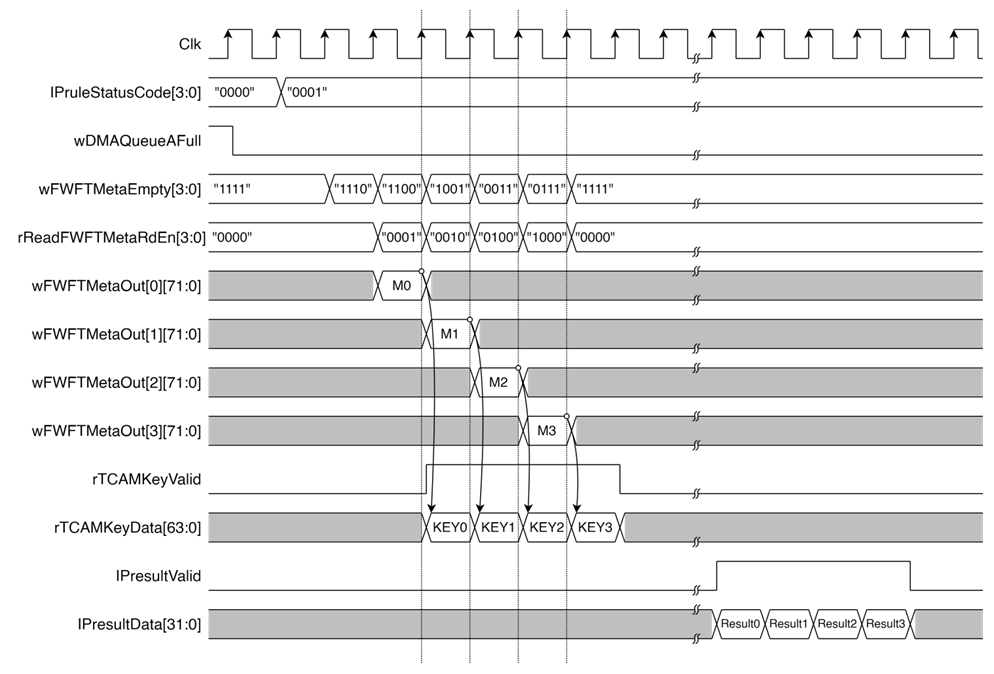
Figure 8 Example timing diagram of tCAM-IP Key Search
2.3.5 PacketMover
As shown in Figure 9, once the tCAM-IP completes the search, with IPresultValid=‘1’, the system uses IPresultValid[9:0] to read data from the Match Table. The data is provided through the MemRdDataA[15:0] signal, where MemRdDataA[3:0] indicates the destination ethernet channel, and MemRdDataA[15:4] is reserved.
In this design, the Match Table is implemented using dual-port RAM. Port A is dedicated to reading data based on the results from the tCAM-IP, while Port B is reserved for user read/write operations. After reading from the Match Table, the data is written to a FIFO to buffer it for the PacketMover. The signal rDMAQueueAdd='1' is asserted to confirm that the data in wDMAQueueValue[17:0] is ready.
The fields of wDMAQueueValue are as follows:
l wDMAQueueValue[11:0] specifies the length of the ethernet packet in 32-bit words.
l wDMAQueueValue[13:12] indicates the source ethernet buffer from which the data should be moved.
l wDMAQueueValue[17:14] specifies the target ethernet buffer(s) where the data should be transferred.
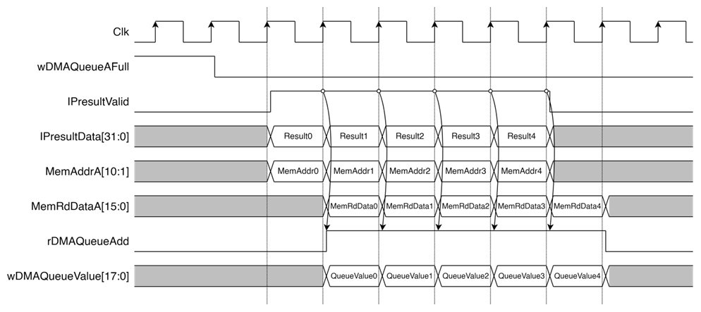
Figure 9 Example timing of tCAM-IP lookup and Match Table access for ethernet packet forwarding
The PacketMover module starts in the “stIdle” state. When the FIFO status is detected as not empty (aDMAQueueEmpty=‘0’), the module reads data from the FIFO and transitions to the “stCheckBusy” state. At this point, it checks whether the source ethernet buffer is busy using the rDMASrcBusy[3:0] signal, and also checks if the target ethernet buffer(s) are busy using rDMADesBusy[3:0]. Additionally, it ensures that the target ethernet information buffer(s) are not almost full by checking the wFWFTMetaTxAFull[3:0] signal. If both the source and target buffers are ready, the state changes to “stDMAStart”, where the system initiates reading from the source and sends data to the target. Once the data transfer starts, the system returns to the “stIdle” state, ready to handle the next ethernet packet transfer.
As shown in Figure 10, this process shows the transfer of an ethernet packet from PacketParser Module 0 to PacketTransfer Module 0. The process begins by reading data from the FIFO by asserting wDMAQueueRdEn=‘1’. In the “stCheckBusy” state, the system verifies that the source and target buffers are ready for operation (rDMASrcBusy[0]=‘0’, rDMADesBusy[0]=‘0’, wFWFTMetaTxAFull[0]=‘0’). Once the buffers are ready, it transitions to the “stDMAStart” state and then returns to “stIdle” in the next clock cycles. The signal wFWFTDataRdEn[0]=‘1’ is asserted to read data from the PacketParser, and this data is sent to the PacketTransfer module through the wFWFTBuffTxIn[0][191:0] signal. The wFWFTBuffTxWrEn[0]=‘1’ signal is set to confirm the write data.
When the final part of the ethernet packet is being sent, the length of the packet, measured in 32-bit words, is written to rFWFTMetaTxIn[0][15:0], and wFWFTMetaTxWrEn[0]=‘1’ is asserted to confirm the transfer to the PacketTransfer module. In the following clock cycle, the rDMASrcBusy[0] and rDMADesBusy[0] signals return to zero, indicating that both the source and target buffers are available for the next operation.
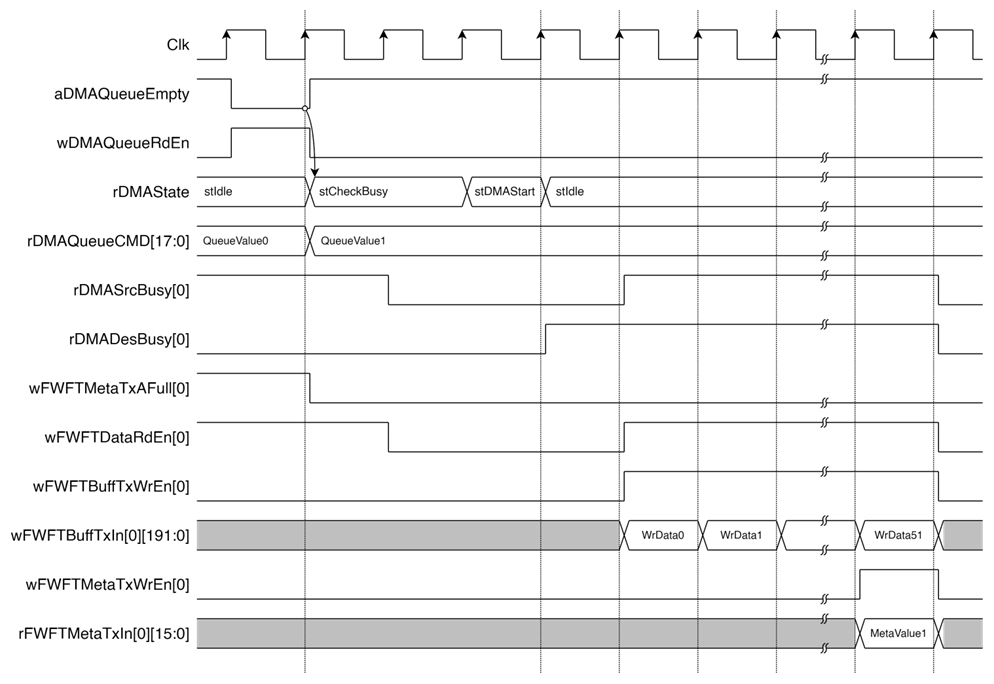
Figure 10 Example of ethernet packet transfer from PacketParser Module 0 to PacketTransfer Module 0
As shown in Figure 11, the scenario demonstrates the case where an ethernet packet from PacketParser Module 0 is decided not to be forwarded to any ethernet destination. The process begins with reading data from the FIFO by setting wDMAQueueRdEn=‘1’. In the “stCheckBusy” state, the system checks that the source buffer is available (rDMASrcBusy[0]='0'). Once confirmed, the state transitions to stFlushBuff, and then returns to “stIdle” in the next clock cycles.
The length of the ethernet packet, measured in 32-bit words, is written to wAFWFTDataFlushCnt[0][11:0], and the signal rFWFTDataFlush[0]='1' is asserted, instructing PacketParser Module 0 to flush the packet. This discards the ethernet packet without forwarding it to any destination, ensuring filtering of unnecessary packets.
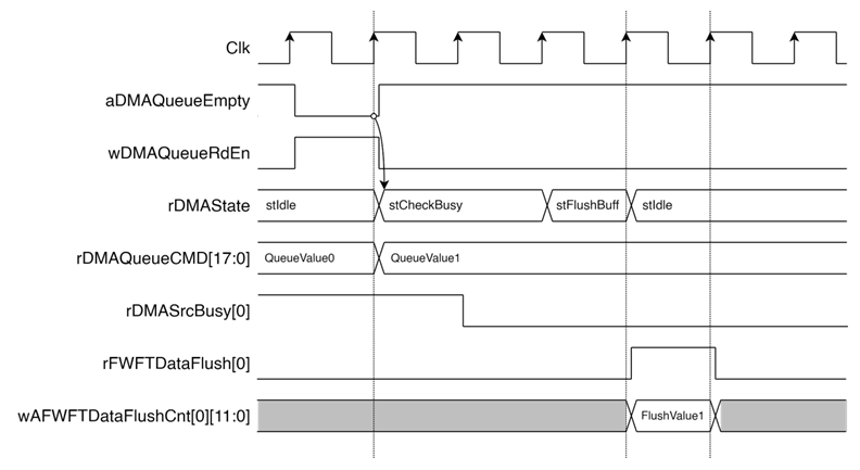
Figure 11 Ethernet Packet Flush Process in PacketParser Module 0
2.4 LL10GEMAC
The IP core by Design Gateway implements low-latency EMAC and PCS logic for 10Gb Ethernet (BASE-R) standard. The user interface is 32-bit AXI4-stream bus. Please see more details from LL10GEMAC datasheet on our website.
https://dgway.com/products/IP/Lowlatency-IP/dg_ll10gemacip_data_sheet_xilinx_en/
2.5 Xilinx Transceiver (PMA for 10GBASE-R)
PMA IP core for 10Gb Ethernet (BASE-R) can be generated by using Vivado IP catalog. In FPGA Transceivers Wizard, The settings are divided into two tabs:
Basic Tab:
l Transceiver configuration preset : GT-10GBASE-R
l Encoding/Decoding : Raw
l Transmitter Buffer : Bypass
l Receiver Buffer : Bypass
l User/Internal data width : 32
Optional Features Tab:
l Buffer Control
l Receiver elastic buffer bypass mode : Single-lane mode
The example of Transceiver wizard in Ultrascale model is described in the following link.
https://www.xilinx.com/products/intellectual-property/ultrascale_transceivers_wizard.html
2.6 PMARstCtrl
When the buffer inside Xilinx Transceiver is bypassed, the user logic must control reset signal of Tx and Rx buffer. The module is designed by state machine to run following step.
1) Assert Tx reset of the transceiver to ‘1’ for one cycle.
2) Wait until Tx reset done, output from the transceiver, is asserted to ‘1’.
3) Finish Tx reset sequence and de-assert Tx reset to allow the user logic beginning Tx operation.
4) Assert Rx reset to the transceiver.
5) Wait until Rx reset done is asserted to ‘1’.
6) Finish Rx reset sequence and de-assert Rx reset to allow the user logic beginning Rx operation.
3 CPU Firmware
After the system boots, the CPU initializes peripheral devices such as UART and Timer, then displays the supported commands. The main function runs in an infinite loop to receive command input from the user. Users can directly configure various parameters and manage UDP packet switching applications through the serial console. The details of each command are as follows:
3.1 Show Access List
command> showlist
Users can display all access list entries, including detailed information for UDP packet switching, by inputting showlist. The showRuleTable function is called to read data from the Rule Table and Match Table to display all access list entries. The showRuleTable function is described in Table 2.
Table 2 showRuleTable function
|
void showRuleTable(uint16_t *table_base_addr, uint16_t *match_base_addr, uint32_t rule_cnt) |
|
|
Parameter |
table_base_addr: Pointer to the base address of the Rule Table. match_base_addr: Pointer to the base address of the Match Table. rule_cnt: The number of rules in the rule table to be displayed. |
|
Return value |
None |
|
Description |
This function prints the rules from the rule table and their associated actions from the match addresses. |
3.2 Add Access List Entry
command> addlist <action> <protocol> <ip-addr> [-m ip-mask] [-p port]
Users can add a new entry to the access list by inputting addlist followed by the action, protocol (TCP, UDP, ICMP), and additional parameters. The addRuleTable function is called to add a new rule to the Rule Table and reinitialize rule of tCAM-IP. The addRuleTable function is described in Table 3.
Table 3 addRuleTable function
|
int addRuleTable(char *arg_str[], uint32_t arg_cnt, uint32_t *rule_cnt) |
|
|
Parameter |
arg_str: Array of pointers to the command-line arguments for adding the rule. arg_cnt: The number of arguments in the ‘arg_str’ array. rule_cnt: Pointer to the total number of rules. |
|
Return value |
0 on success, otherwise -1 if there is an error. |
|
Description |
This function processes command-line arguments to add a rule to the rule table. |
3.3 Move Access List Entry
command> movelist <list number> -d [number] | -u [number]
Users can move an access list entry up or down in the list by inputting movelist followed by the direction. The movRuleTable function is called to move a rule within the Rule Table and reinitialize rule of tCAM-IP. The movRuleTable function is described in Table 4.
Table 4 movRuleTable function
|
int movRuleTable(uint32_t rule_cnt, uint32_t rule_num, uint32_t direct, uint32_t mov_num) |
|
|
Parameter |
rule_cnt: The total number of rules in the rule table. rule_num: The number of the rule to be moved. direct: The direction of the move (1: MOVE_UP or 0: MOVE_DOWN). mov_num: The number of positions to move the rule. |
|
Return value |
0 on success, otherwise -1 if there is an error. |
|
Description |
This function moves a rule within the rule table, either up or down by a specified number of positions. |
3.4 Remove Access List Entry
command> removelist <list number>
Users can remove an access list entry by inputting removelist followed by access list number entry. The delRuleTable function is called to delete a rule from the Rule Table and reinitializes the tCAM-IP. The delRuleTable function is described in Table 5.
Table 5 delRuleTable function
|
int delRuleTable(unsigned int *rul_cnt, unsigned int rul_number) |
|
|
Parameter |
rule_cnt: Pointer to the total number of rules. rule_number: The number of the rule to be deleted. |
|
Return value |
0 on success, otherwise -1 if there is an error. |
|
Description |
This function removes a specified rule from the Rule Table. It handles adjusting the positions of the remaining rules and reinitializes the tCAM-IP with the updated rule count. |
3.5 Clear All Access List Entries
command> clearlist
Users can clear all access list entries by inputting clearlist. This command sets the total number of rules to zero and reinitializes the tCAM-IP.
3.6 Show Network Status
command> netstatus
Users can display the status of ethernet by inputting netstatus. The ethlinkStatus function is called to display the status of Ethernet links for all interfaces. The ethlinkStatus function is described in Table 6.
Table 6 ethlinkStatus function
|
void ethlinkStatus(void) |
|
|
Return value |
None |
|
Description |
This function reads the Ethernet link status from a register and prints whether each ethernet interface (0 through 3) is "Link Up" or "Link Down". |
3.7 Configure Comparison Mode
command> configmode <src|des>
Users can configure the comparison mode by inputting configmode followed by “src” to use the source network parameter or “des” to use the destination network parameter for filtering and switching UDP packets. This command sets the USER_PARSER_MODE_REG for the PacketParser.
4 Revision History
|
Revision |
Date (D-M-Y) |
Description |
|
1.00 |
2-Oct-24 |
Initial version release |