tCAM-IP Reference Design
1 Introduction
This document describes the details of the tCAM-IP reference design. In this reference design, the tCAM-IP is used to search for a key provided by the user, based on rules defined in the Rule Table. Users can configure rules, input keys, and control the test operation via the serial console on a test PC. More details of the hardware design and CPU firmware are described as follows.
2 Hardware Overview
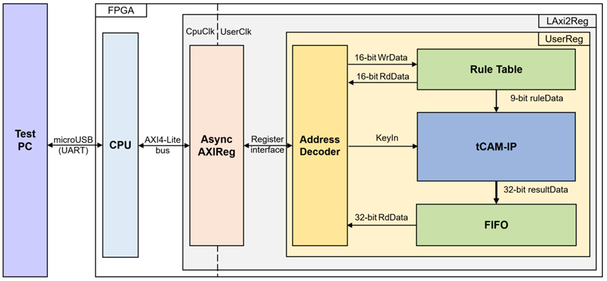
Figure 1 tCAM-IP reference design block diagram
In this test environment, as shown in Figure 1, the tCAM-IP is integrated into the UserReg module, which is connected to the CPU via AsyncAXIReg using a register interface. The CPU communicates with AsyncAXIReg through the AXI4-Lite interface. The tCAM-IP interacts with the Rule Table for initializing rules, and users can define keys via the register interface. The search results are stored in a FIFO, allowing users to retrieve and utilize them later. The details of each module are described as follows.
2.1 LAxi2Reg
The LAxi2Reg module is connected to the CPU through the AXI4-Lite bus. The hardware registers are mapped to the CPU’s memory address, as shown in Table 1. This module is responsible for the control and status registers that the CPU accesses via LAxi2Reg.
LAxi2Reg is composed of two main components: AsyncAxiReg and UserReg. The AsyncAxiReg converts the AXI4-Lite signals into a simple register interface with a 32-bit data bus size (similar to that of AXI4-Lite). As depicted in Figure 1, two clock domains are applied in this block: CpuClk, used for interfacing with the CPU via the AXI4-Lite bus, and UserClk, which serves as the user clock domain for tCAM-IP. The AsyncAxiReg includes asynchronous circuitry to manage the interaction between the CpuClk and UserClk domains.
The UserReg module contains the register file, which stores parameters and status signals related to test logic, including user logic and the tCAM-IP. Further details on AsyncAxiReg and UserReg are provided in the following sections.
2.2 AsyncAxiReg
This module is designed to convert the AXI4-Lite signal interface into a register interface, while enabling communication between two clock domains.
For writing to a register, the RegWrEn signal is asserted to '1' along with valid signals for RegAddr (the register address in 32-bit units), RegWrData (the write data for the register), and RegWrByteEn (the byte enable for this access: bit[0] controls write enable for RegWrData[7:0], bit[1] for RegWrData[15:8], and so on, with bit[3] controlling RegWrData[31:24]).
To read from a register, the AsyncAxiReg module asserts RegRdReq to '1' with a valid value for RegAddr (the register address in 32-bit units). The module then waits for the RegRdValid signal to be asserted to '1', at which point the read data is received through the RegRdData signal within the same clock cycle.
The register interface address is shared for both write and read transactions, meaning that a user cannot perform read and write operations on the same register simultaneously. The timing diagram for the register interface is shown in Figure 2.
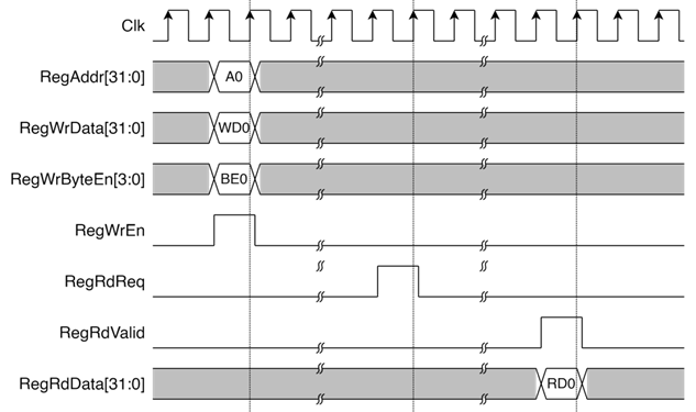
Figure 2 Register interface timing diagram
2.3 UserReg
For register file, UserReg is designed to write/read registers, control and check alert of the tCAM-IP corresponding with write register access or read register request from AsyncAvlReg module. The memory map inside UserReg module is shown in Table 1.
Table 1 Register map Definition
|
Address |
Register Name |
Rd/Wr |
Description |
|
0x0000 |
TCAM_RSTB_REG |
Wr |
[0] - Reset signal active low (rTCAMRstB). |
|
0x0004 |
TCAM_VERSION_REG |
Rd |
[31:0] - tCAM IP version (IPversion[31:0]). |
|
0x0008 |
TCAM_STATUS_REG |
Rd |
[3:0] - tCAM status code (IPruleStatusCode[3:0]) |
|
0x000C |
TCAM_START_REG |
Rd |
[0] - tCAM initail operations busy status (IPruleBusy). |
|
Wr |
[0] - tCAM initail start flag (rTCAMInitStart). |
||
|
0x0010 |
TCAM_RULEWIDTH_REG |
Wr |
[15:0] - Number bits of rule (rTCAMRuleWidth[15:0]). |
|
0x0014 |
TCAM_RULECOUNT_REG |
Wr |
[31:0] -
Number of rules to initialize tCAM |
|
0x0020 |
TCAM_KEY_HIGH_REG |
Wr |
[31:0] -
Upper 32 bits of key data |
|
0x0024 |
TCAM_KEY_LOW_REG |
Wr |
[31:0] -
Lower 32 bits of key data |
|
0x0028 |
TCAM_KEY_VALID_REG |
Wr |
[0] - Key valid flag (rTCAMKeyValid). |
|
0x0040 |
USER_BUFFER_AVAILABLE_REG |
Rd |
[0] - FIFO empty flag (FIFOEmpty). |
|
Wr |
[0] - Clear buffer (rUserClearBuff). |
||
|
0x0044 |
USER_BUFFER_RDDATA_REG |
Wr |
[31:0] - Data read from FIFO (FIFORdData[31:0]). |
|
0x4000 |
TCAM_RULE_BASE_ADDR |
Rd/Wr |
Base address for tCAM rule configuration. |
2.3.1 tCAM-IP Rule Initialize
In the reference design, the tCAM-IP analyzes network parameters to determine if they match any entries in the access list and identifies which list entry corresponds to the packet. Whenever the access list is modified, users must reinitialize the rules for the tCAM-IP. The width of the rule can be set by writing to the TCAM_RULEWIDTH_REG, which maps to the signal rTCAMRuleWidth[15:0]. Additionally, users can specify the number of rules by writing to the TCAM_RULECOUNT_REG, which maps to rTCAMRuleCount[31:0]. To begin the rule initialization process, the user writes to the TCAM_START_REG, where the signal rTCAMInitStart is set to 1 for one clock cycle.
While the tCAM-IP is initializing the rules, it reads data from the Rule Table by sending IPruleAddr[31:0] along with IPruleRdReq=’1’. In this design, the Rule Table is implemented as dual-port RAM. Port A is available for users to read and write rules, while Port B is dedicated to tCAM-IP for reading. The read process from Port B has a latency of 1 clock cycle, and the signal rTCAMRuleReadValid=‘1’ confirms that the data retrieved from the Rule Table (via RamRdDataA[8:0]) is valid.
Users can confirm that the tCAM-IP has completed the rule initialization by checking if IPruleBusy=‘0’, which can be read from TCAM_START_REG. Once the tCAM-IP has successfully initialized the rules, users should verify that IPruleStatusCode[3:0]=“0001”, indicating that the rule initialization has been successfully completed and the tCAM-IP is ready for use. This status can be read from TCAM_STATUS_REG.
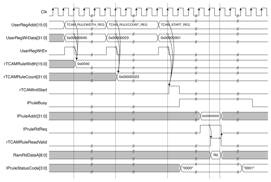
Figure 3 Example of tCAM-IP Rule initialize
2.3.2 tCAM-IP Key Search
In the reference design, users can input a key by writing to the TCAM_KEY_LOW_REG to set rTCAMKeyData[31:0] and to the TCAM_KEY_HIGH_REG to set rTCAMKeyData[63:32]. Once the key is configured, users can start the tCAM-IP search operation by writing to the TCAM_KEY_VALID_REG, setting the signal rTCAMKeyValid to ‘1’ only one clock cycle.
When the tCAM-IP completes the search, it writes the result to the FIFO. Users can check USER_BUFFER_AVAILABLE_REG to verify if data is available in the FIFO. Once it is confirmed that the FIFO is not empty (FIFOEmpty='0'), users can read the search result from USER_BUFFER_RDDATA_REG, which retrieves the tCAM-IP search result through the signal FIFORdData[31:0].
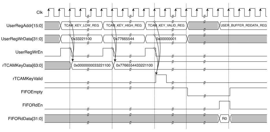
Figure 4 Example of tCAM-IP Key Search
3 CPU Firmware
After the system boots, the CPU initializes peripheral devices such as UART and Timer and then displays the commands. The main function operates in an infinite loop, continuously receiving command inputs from the user. Through the serial console, users can directly configure various parameters and manage the tCAM-IP. The details of each command are described as follows:
3.1 Initial Rule Table
This command initializes the tCAM-IP rule table by loading user-defined rules from the serial console. The function validates and stores the rules at a specified base address and ensures that the tCAM-IP is properly initialized with these rules. The process is handled by calling the init_rule_table function as described below:
Steps performed by the function:
1) The function first receives the rule width from the user via the serial console, specifying the number of bytes for each rule.
2) After receiving the rule width, it collects the rule data from the user and calculates the total number of rules to be initialized.
3) The input is checked to ensure that both the rule width and the number of rules are within the allowed system limits and follow the correct format.
4) The validated rules are then written to the tCAM-IP's rule table, starting at the specified base address in memory.
5) After the rules are stored, the function signals the tCAM-IP to begin the initialization process.
6) Finally, the function checks the status of the tCAM-IP to confirm that the rule initialization was completed successfully.
Table 2 init_rule_table function
|
int init_rule_table(uint16_t *base_addr, uint32_t *rule_width, uint32_t *rule_count) |
|
|
Parameter |
base_addr: Pointer to the base address where rules will be stored. rule_width: Pointer to store the width of each rule in bytes. rule_count: Pointer to store the total number of rules initialized. |
|
Return value |
0 on success, -1 on input error or tCAM-IP initialization error. |
|
Description |
This function initializes the rule table with user-defined rules from serial console. |
3.2 Display Rule Table
This command is used to display the rules stored at a specified memory address by calling the display_rule_table function. The function begins by printing the width of each rule and the total count of rules. It then iterates through the rules, retrieving and formatting each rule's data from the memory address pointed to by base_addr. The rules are presented in a structured format, showing the byte values for each rule sequentially.
Table 3 display_rule_table function
|
void display_rule_table(uint16_t *base_addr, uint32_t rule_width, uint32_t rule_count) |
|
|
Parameter |
base_addr: Pointer to the base address in memory where the rule data starts. rule_width: The width of each rule in bytes. rule_count: The total number of rules to display. |
|
Return value |
None. |
|
Description |
Displays a table of rules from a specified memory address. |
3.3 Key Search
This command reads the keys from the serial console as provided by the user and searches for these keys using the tCAM-IP to find matches against the entries defined in the rules by calling the key_search function. The steps involved in this process are as follows:
1) The function starts by reading the keys from the serial console as provided by the user.
2) It processes these keys based on the specified rule width, which is defined by rule_width.
3) The function then checks the tCAM-IP search results and displays them.
4) During this process, it counts the total number of keys that were processed and how many of those matched.
Table 4 key_search function
|
int key_search(uint32_t rule_width) |
|
|
Parameter |
rule_width: The width of each rule in bytes. |
|
Return value |
0 on successful completion, -1 on error due to invalid key or width issues. |
|
Description |
Displays a table of rules from a specified memory address. |
3.4 Initial Word Table
This command initializes the tCAM-IP rule word table and replaces the word table by loading user-defined rules from the serial console. The function validates and stores the rules at a specified base address and ensures that the tCAM-IP is properly initialized with these rules. The process is handled by calling the init_word_table function as described below:
1) The function first receives the rule width from the user via the serial console, specifying the number of bytes for each rule.
2) After receiving the rule width, it collects the rule word and replace word from the user and calculates the total number of rules to be initialized.
3) The input is checked to ensure that both the rule width and the number of rules are within the allowed system limits and follow the correct format.
4) The validated rules are then written to the tCAM-IP's rule table, starting at the specified base address in memory.
5) After the rules are stored, the function signals the tCAM-IP to begin the initialization process.
6) Finally, the function checks the status of the tCAM-IP to confirm that the rule initialization was completed successfully.
Table 5 init_rule_table function
|
int init_word_table(uint16_t *rule_base_addr, uint8_t *replace_base_addr, uint32_t *rule_width, uint32_t *rule_count) |
|
|
Parameter |
rule_base_addr: Pointer to the base address where rules will be written. replace_base_addr: Pointer to the base address where replacement values will be written. rule_width: Pointer to store the width of each rule. rule_count: Pointer to store the number of rules processed. |
|
Return value |
0 on success, -1 on input error or tCAM-IP initialization error. |
|
Description |
This function initializes the rule table and replaces the word table with user-defined rules from serial console. |
3.5 Display Word Rule
This command is used to display the rules along with their corresponding replacement values stored at specified memory addresses by calling the display_word_table function. The function begins by printing the width of each rule and the total count of rules. It then iterates through the rules, retrieving and formatting each rule's data from the memory address pointed to by rule_base_addr, as well as the associated replacement values from replace_base_addr. The rules and their replacements are presented in a structured format, showing the byte values for each rule and its corresponding replacement sequentially.
Table 6 display_word_table function
|
void display_word_table(uint16_t *rule_base_addr, uint8_t *replace_base_addr, uint32_t rule_width, uint32_t rule_count) |
|
|
Parameter |
rule_base_addr: Pointer to the base address in memory for rule data. replace_base_addr: Pointer to the base address in memory for replacement data. rule_width: The width of each rule in bytes. rule_count: The total number of rules to display. |
|
Return value |
None. |
|
Description |
Displays a table of rules with their corresponding replacement values. |
3.6 Search Replace
This command is used to receive words from the serial console as provided by the user and apply them to the tCAM-IP for search and replacement operations. By calling the search_replace function, the system checks if the incoming word matches any of the predefined rules. If a match is found, the corresponding replacement word will be displayed; if not, the original word will be shown instead. After the operation, the command will report the total number of searches conducted and how many words were replaced. The steps involved in this process are as follows:
1) The function starts by reading words from the serial console as provided by the user.
2) It processes these words based on the specified rule width, defined by rule_width.
3) The function checks the tCAM-IP search results and displays the corresponding output.
4) During this process, the function counts the total number of words processed and the number of words that were successfully replaced.
Table 7 search_replace function
|
int search_replace(uint32_t rule_width, uint8_t *replace_base_addr) |
|
|
Parameter |
rule_width: The width of the rules for matching words. replace_base_addr: Pointer to the base address where replacement words are stored. |
|
Return value |
0 on successful completion, -1 on error due to invalid character. |
|
Description |
This function processes input for searching and replacing words using tCAM-IP. |
4 Revision History
|
Revision |
Date (D-M-Y) |
Description |
|
14-Oct-24 |
Update table of contents. |
|
|
2.00 |
2-Oct-24 |
Improve reference design to be standalone version. |
|
1.00 |
30-Jun-21 |
Initial version release. |