AES256GCM10G25G-IP Demo Instruction
2 FPGA Development Board Setup
2.1 ZCU106, ZCU102 Board Setup
4 Command Details and Test Results
This document describes the instruction to demonstrate the operation of AES256GCM10G25G-IP on FPGA Evaluation Board. In the demonstration, AES256GCM10G25G-IP, called AESGCM-IP, is used to encrypt/decrypt data between two memories in FPGA and provide authentication tag. User can fill memory with Additional Authenticated Data (AAD), DataIn patterns, set encryption/decryption key, Initialization Vector (IV), and control test operation via serial console.
1 Environment Setup
To operate AESGCM-IP demo, please prepare following test environment.
a) FPGA development board.
b) Test PC.
c) Micro USB cable for JTAG connection between FPGA board and Test PC.
d) Micro USB cable for UART connection between FPGA board and Test PC.
e) Vivado tool for programming FPGA installed on Test PC.
f) Serial console software such as TeraTerm installed on PC. The setting on the console is Baudrate=115,200, Data=8-bit, Non-parity and Stop=1.
g) Demo configuration file (To download this file, please visit our web site at www.design-gateway.com).

Figure 1 AESGCM-IP demo environment on ZCU106 board
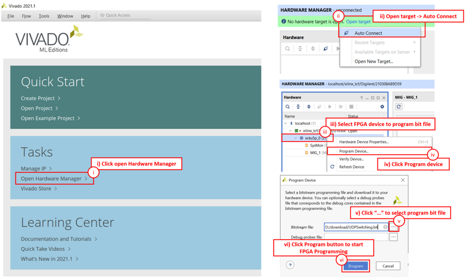
Figure 2 AESGCM-IP demo environment on ZCU102 board
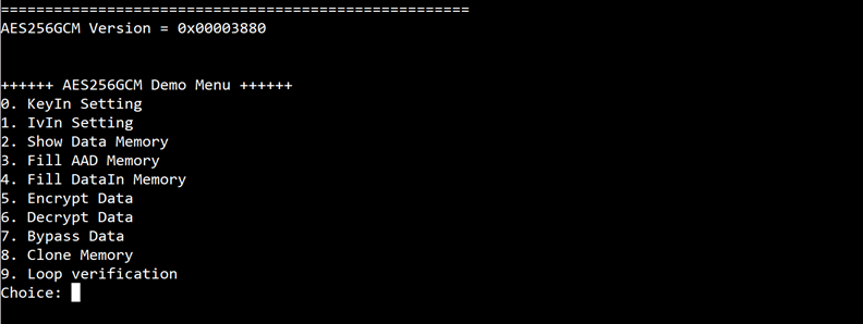
Figure 3 AESGCM-IP demo environment on KR260 board
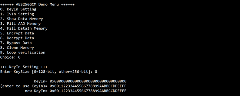
Figure 4 AESGCM-IP demo environment on KCU116 board
2 FPGA Development Board Setup
2.1 ZCU106, ZCU102 Board Setup
1) Make sure power switch is off and connect power supply to FPGA development board.
2) Connect USB cable between PC to JTAG micro USB port.
3) Power on the system.
4) Download configuration file and firmware to FPGA board by following step
i) Open Vivado TCL shell.
ii) Change current directory to download folder which includes demo configuration file.
iii) Run bat script to program bit file, as show in Figure 5.
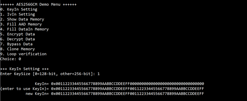
Figure 5 Program Device on ZCU102
2.2 KR260 Board Setup
1) Make sure power switch is off and connect power supply to FPGA development board.
2) Connect USB cable between PC to JTAG micro USB port.
3) Power on the system.
4) Download configuration file and firmware to FPGA board by following step
i) Open Xilinx XSCT.
ii) Change current directory to download folder which includes demo configuration file.
iii) Run tcl script to program bit file, as show in Figure 6.
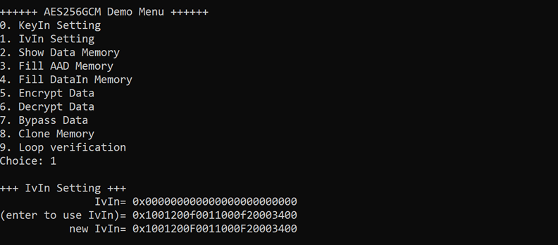
Figure 6 Program Device on KR260
2.3 KCU116 Board Setup
1) Make sure the power switch is off and connect the power supply to FPGA development board.
2) Connect USB cable between PC to JTAG micro USB port.
3) Power on the system.
4) Open Vivado Hardware Manager to program FPGA by following steps.
i) Click open Hardware Manager.
ii) Open target -> Auto Connect.
iii) Select FPGA device to program bit file.
iv) Click Program device.
v) Click “…” to select program bit file.
vi) Click Program button to start FPGA Programming.
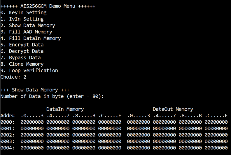
Figure 7 Program Device on KCU116
3 Serial Console
User can fill RAMs with AAD, plain or cipher data patterns, set encryption/decryption key, IV and control test operation via serial console. When configuration is completed, AESGCM-IP demo command menu will be displayed as shown in Figure 8. The detailed information of each menu is described in topic 4.
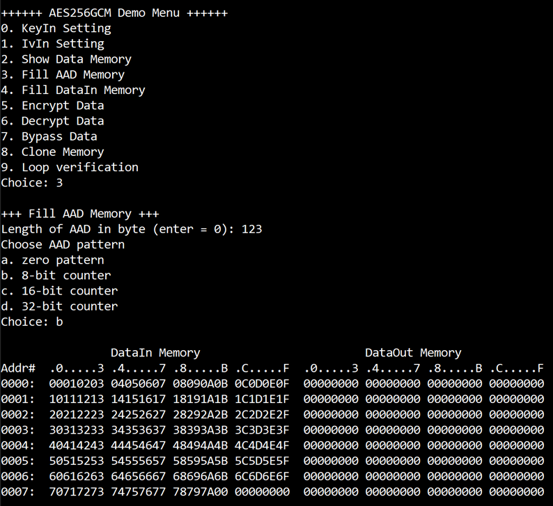
Figure 8 Serial Console
4 Command Details and Test Results
4.1 KeyIn Setting
Step to set key as follows
a) Select “KeyIn Setting”.
b) Choose Key Size:
· Enter 0 for 128-bit key.
· Enter other for 256-bit key.
c) Current key will be displayed on serial console as shown in Figure 9.
d) Set new key: User is allowed to input new key in hex format or press “enter” to skip setting new key. Then the current key is printed again.
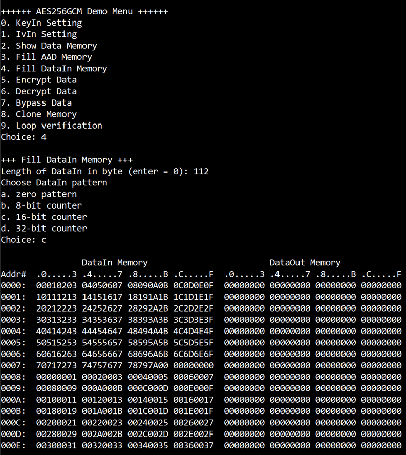
Figure 9 KeyIn setting example for 128-bit key
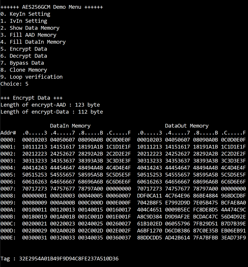
Figure 10 KeyIn setting example for 256-bit key
4.2 IvIn Setting
Step to set IV as follows
a) Select “IvIn Setting”.
b) Current IV will be displayed on serial console as shown in Figure 11.
c) Set new IV: User is allowed to input new IV in hex format or press “enter” to skip setting new IV. Then the current IV is printed again.
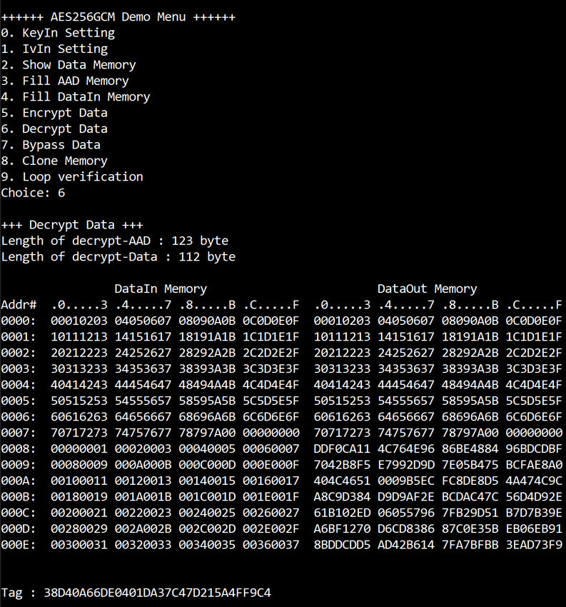
Figure 11 IvIn setting example
4.3 Show Data Memory
To show data in memory, user can select “Show Data Memory”. User can input the desired length of data in byte to show. The data length will be aligned to 128 bits. DataIn and DataOut will be displayed in table-form as shown in Figure 12. User can press “enter” to use 80 bytes as default value.
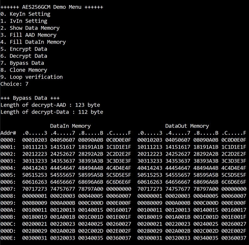
Figure 12 Displayed data when input the desired length of data
4.4 Fill AAD Memory
Step to set AAD as follows
a) Select “Fill AAD Memory”.
b) Input the desired length of AAD in byte. In case of zero-length AAD operation, user can input “0” or press “enter” then end process of this menu. In case of non-zero-length AAD, user can select AAD pattern as shown in Figure 13.
c) There are four pattern to fill AAD memory.
a. zero pattern
b. 8-bit counter
c. 16-bit counter
d. 32-bit counter
d) AAD memory will be filled with selected pattern by the number of AAD and zero-padding to become 128-bit padded data.

Figure 13 Displayed data when set AAD pattern
4.5 Fill DataIn Memory
Step to fill DataIn in memory as follows
a) Select “Fill DataIn Memory”.
b) Input the desired length of data in byte. In case of zero-length DataIn operation, user can input “0” or press “enter” on keyboard then end process of this menu. In case of non-zero-length DataIn, user can select data pattern.
c) There are four pattern to fill memory.
a. zero pattern
b. 8-bit counter
c. 16-bit counter
d. 32-bit counter
d) Whole DataIn memory is filled with selected pattern after AAD according to the number of input data length as displayed in Figure 14.
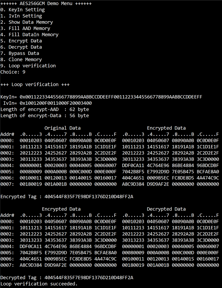
Figure 14 Displayed data when setting DataIn length and data pattern
4.6 Encrypt Data
Select “Encrypt Data” to encrypt DataIn in memory. Current length of AAD and length of DataIn are printed on serial console. When the encryption process is finished, both DataIn and DataOut will be displayed in table-form and 128-bit encryption tag will be printed as shown in Figure 15.

Figure 15 Serial console after finished encryption process
4.7 Decrypt Data
Select “Decrypt Data” to decrypt DataIn in memory. Current length of AAD and length of DataIn are printed on serial console. When the decryption process is finished, both DataIn and DataOut will be displayed in table-form and 128-bit decryption tag will be printed as shown in Figure 16.

Figure 16 Serial console after finished decryption process
4.8 Bypass Data
Select “Bypass Data” to bypass DataIn in memory. Current length of AAD and length of DataIn are printed on serial console. When the Bypass process is finished, both DataIn and DataOut will be displayed in table-form as shown in Figure 17.

Figure 17 Serial console after finished Bypass process
4.9 Clone Memory
Select “Clone Memory” to copy the DataOut memory to the DataIn memory. When the process is finished, both DataIn and DataOut will be displayed in table-form as shown in Figure 18.

Figure 18 Serial console after finished Clone Memory process
4.10 Loop Verification
Select “Loop verification”, to check both encryption and decryption. In this menu, DataIn in memory will be encrypted/decrypted with all current parameters (key, IV, AAD and data in DataIn memory).
The function begins by reading and storing data from the DataIn memory as the original data. It then clears the DataOut memory before starting the encryption process. After the encryption is completed, the data from the DataOut memory is cloned to the DataIn memory and decryption process is performed. Once the decryption is completed, the decrypted data is compared with the original data, and the encryption tag is compared with the decryption tag.
If the decrypted data and decryption tag match with original data and encryption tag, respectively, “Loop verification succeeded.” is printed on serial console as shown in Figure 19.

Figure 19 Serial console after loop verification is succeeded
4.11 NIST Test Vector
Select “NIST Test Vector” to verify both encryption and decryption operations using standardized test data provided in NIST’s official RSP format. The system receives input parameters through the serial console, following the format used in the NIST test vector files.
During the process, the firmware reads and interprets each parameter from the user input, including the key, IV, plaintext (PT), additional authenticated data (AAD), ciphertext (CT), and tag. These values are used to configure the encryption or decryption settings of the hardware.
Once the required parameters are entered, the system automatically performs the cryptographic operation. After completion, it checks the result by comparing the output data and authentication tag with the expected values defined in the test vector file. If all values match, the response “OK” is displayed. If any part does not match, the system displays “NG”. If there is no received uart data for more than 100 milliseconds, the test session ends automatically.

Figure 20 Serial console screen after selecting “NIST Test Vector”

Figure 21 Example of sending a test vector file through UART

Figure 22 Sample GCM decryption test vector with 128-bit key in RSP format

Figure 23 Example of test progress and validation during execution
Note:
You can download official test vector files directly from the NIST website at
the following URL:
https://csrc.nist.gov/CSRC/media/Projects/Cryptographic-Algorithm-Validation-Program/documents/mac/gcmtestvectors.zip
These test vectors are also included in the “gcmtestvectors” folder within the
demo configuration package (last updated on 22-May-2025).
Because the UART communication is set to 115200 baud, data is transferred at approximately 11,520 bytes per second. For large test files, such as 1 MB, transmission may take up to 90 seconds. Users should be aware of this delay and ensure the serial terminal remains open throughout the test.
5 Revision History
|
Revision |
Date (D-M-Y) |
Description |
|
2.02 |
28-May-25 |
- Add support for NIST test vectors. |
|
2.01 |
1-Nov-24 |
- Revise wording. - Correct missing cross-reference. |
|
2.00 |
14-Oct-24 |
Update KeyIn Setting command |
|
1.00 |
1-Jan-24 |
Initial version release |