
|
Core Facts |
|
|
Provided with Core |
|
|
Documentation |
User Guide, Design Guide |
|
Design File Formats |
Encrypted File |
|
Instantiation Templates |
VHDL |
|
Reference Designs & Application Notes |
Vivado Project, See Reference design manual |
|
Additional Items |
Demo on |
|
Support |
|
|
Support Provided by Design Gateway Co., Ltd. |
|
Design Gateway Co., Ltd
E-mail: ip-sales@design-gateway.com
URL: design-gateway.com
Features
· Support AES-GCM mode standard.
· Support 256-bit key size, 96-bit iv size.
· Support zero-length AAD or data input.
· Peak throughput rate at 9.14 Mbits/MHz.
· Speed up to 2.285 Gbps @250MHz.
Table 1 Table Description
|
Family |
Example Device |
Fmax (MHz) |
ALMs |
Registers1 |
Block Memory bit |
Design Tools |
|
Agilex5 E-Series |
A5ED065BB32AE5SR0 |
250 |
4809.6 |
10263 |
- |
Quartus 24.3.1 |
Notes:
1) The actual logic resource depends on the percentage of unrelated logic.
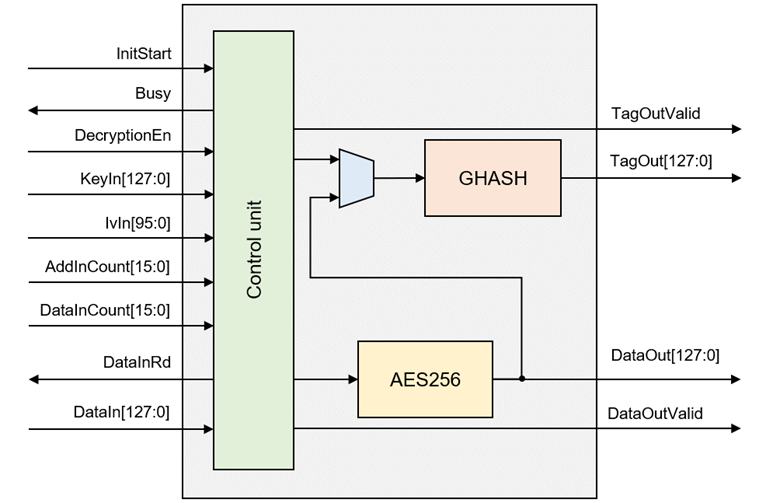
Figure 1 Block Diagram
General Description
AES256-GCM-1G IP Core (AES256GCM1GIP) implement the advanced encryption standard (AES) with 256-bit key in Galois/Counter Mode (GCM) which is widely used for Authenticated Encryption with Associated Data (AEAD) application.
There are 2 main operations in AES-GCM, AES encryption/decryption and tag calculation by GHASH algorithm. AES256GCM1GIP works with 256-bit AES-key and 96-bit Initialization Vector (IV). It can provide confidentiality and data authentication by using Additional Authenticated Data (AAD) and authentication tag. It is designed to support zero-length plaintext/ciphertext input which is the special case of GCM mode, called GMAC, and also support zero-length AAD.
Functional Description
AES256GCM1G interface signals can be divided into 2 parts, i.e. parameter setting signals and data control signals.
Table 2 Interface signals of AES256GCM1G
|
Signal name |
Dir |
Description |
|
RstB |
In |
IP core system reset. Active low. |
|
Clk |
In |
IP core system clock. |
|
version[31:0] |
Out |
32-bit version number of IP |
|
Parameter setting signals |
||
|
InitStart |
In |
InitStart is a user signal to start AES256GCM1G operation. |
|
Busy |
Out |
AES256GCM1G Busy status. Busy is active after user sets InitStart, until operation is done. |
|
Finish |
Out |
Finish specifies finish status of AES256GCM1G. Assert to ‘1’ at the last cycle of operation. |
|
DecryptionEn |
In |
DecryptionEn is a user signal to specify mode of operation. DecryptionEn=‘0’ for encryption, DecryptionEn=‘1’ for decryption. DecryptionEn must be valid during operation. |
|
KeyIn [255:0] |
In |
KeyIn is 256-bit key data for AES block cipher in CTR mode of operation. KeyIn must be valid during operation. |
|
IvIn [95:0] |
In |
IvIn is 96-bit IV data for AES block cipher in CTR mode of operation. IvIn must be valid during operation. |
|
AadInCount[15:0] |
In |
AadInCount is the number of AAD in byte. AadInCount must be valid during operation. |
|
DataInCount[15:0] |
In |
DataInCount is the number of input data in byte. DataInCount must be valid during operation. |
|
Data control signals |
||
|
DataInRd |
Out |
DataInRd is a control signal to read DataIn. |
|
DataIn [127:0] |
In |
DataIn is 128-bit input data, both of AAD and data. DataIn must be valid when DataInRd is asserted to ‘1’. |
|
DataOutValid |
Out |
DataOutValid specifies data valid for DataOut. Assert to ‘1’ when cipher data is valid for encryption mode or plain data is valid for decryption mode. |
|
DataOut [127:0] |
Out |
DataOut is 128-bit data output of AES256GCM1G. Valid when DataOutValid is asserted to ‘1’. |
|
TagOutValid |
Out |
TagOutValid specifies tag valid. Assert to ‘1’ when operation is done, after Busy signal is reset. |
|
TagOut [127:0] |
Out |
TagOut is 128-bit tag output of AES256GCM1G. Valid when TagOutValid is asserted to ‘1’. |
· Parameter setting
AES256GCM1G is designed to start operation when InitStart is asserted to ‘1’. DecryptionEn, KeyIn, IvIn, AadInCount and DataInCount must be valid when InitStart=‘1’ and be hold during operation. User can set DecryptionEn to ‘0’ for operating in encryption mode as shown in Figure 2 or set DecryptionEn to ‘1’ for operating in decryption mode as shown in Figure 3.
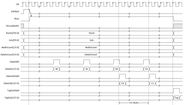
Figure 2 AES256GCM1G timing diagram in encryption mode
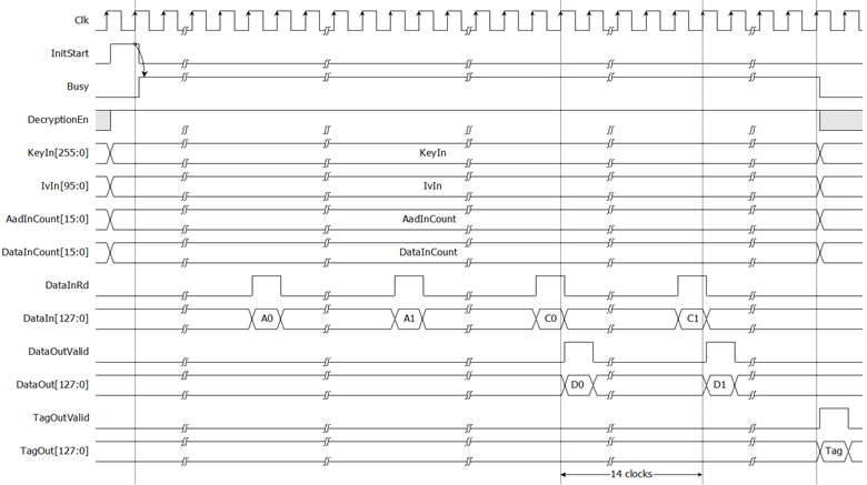
Figure 3 AES256GCM1G timing diagram in decryption mode
For the best performance, user can use Finish as a trigger signal for setting new parameters and sending new start command in next cycle as shown in Figure 4.
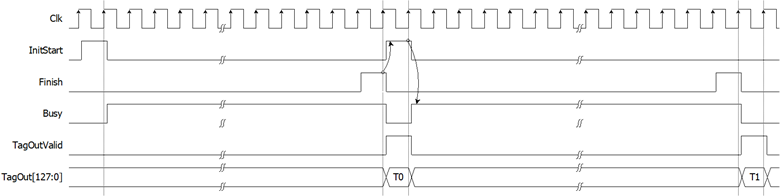
Figure 4 Continuous and pipelining operation
· Data control
After starting operation, DataIn[127:0] must be set and valid when DataInRd is asserted to ‘1’. User need to prepare 128-bit DataIn. In case of non-zero length AAD, if AadInCount is not aligned to 128 bits, the last 128-bit data of AAD must be right-padded with zeros. If DataInCount is non-zero, the next 128-bit data will be plain/cipher data. AES256GCM1G is designed to read DataIn every 14 clock cycles after read the first data. User may use DataInRd as a condition to prepare next 128-bit data.
As shown in Figure 2, after the first DataIn is read, the DataOut is valid in the next clock. In case of zero-length data, DataOutValid is not active during operation. Authentication tag is valid after finished operation. As shown in Figure 3, TagOutValid is active only one clock when Busy is reset to be ‘0’.
Verification Methods
The AES256-GCM-1G IP Core functionality was verified by simulation and also proved on real board design by using Sulfur Agilex5 E-Series boards.
Recommended Design Experience
The user must be familiar with HDL design methodology to integrate this IP into a system.
Ordering Information
This product is available directly from Design Gateway Co., Ltd. Please contact Design Gateway Co., Ltd. For pricing and additional information about this product, use the contact information on the front page of this datasheet.
Revision History
|
Revision |
Date (D-M-Y) |
Description |
|
1.00 |
8-Dec-25 |
Initial release |