AES256XTS IP Core Data Sheet
2. Encryption/Decryption control

Core Facts |
|
|
Provided with Core |
|
|
Documentation |
User Guide, Design Guide |
|
Design File Formats |
Encrypted File |
|
Instantiation Templates |
VHDL |
|
Reference Designs & Application Notes |
Quartus Project, See Reference Design Manual |
|
Additional Items |
Demo on A10SoC, Agilex F-Series development kit |
|
Support |
|
|
Support Provided by Design Gateway Co., Ltd. |
|
Design Gateway Co.,Ltd
E-mail: ip-sales@design-gateway.com
URL: design-gateway.com
Features
· Support AES-XTS mode standard.
· Support 256-bit key size.
· Support input data width128-bit.
· Support Ciphertext Stealing.
· Peak throughput rate at 128Mbits/MHz.
· Speed up to 44.8 Gbps or 5.6 GBps @350MHz.
· Customized service for reduce resource by support 128-bit data alignment only.
Table 1: Example Implementation Statistics for Encryption
|
Family |
Example Device |
Fmax (MHz) |
ALMs |
Registers1 |
Design Tools |
|
Agilex F-Series |
AGFB014R24A2E2VR0 |
350 |
13251.0 |
6718 |
Quartus 20.4 |
|
Arria10 SX |
10AS066N3F40E2SGE2 |
280 |
12595.7 |
5624 |
Quartus 20.4 |
|
Stratix10 GX2 |
1SG280HU2F50E1VG |
300 |
13106.0 |
19116 |
Quartus 20.4 |
Table 2: Example Implementation Statistics for Decryption
|
Family |
Example Device |
Fmax (MHz) |
ALMs |
Registers1 |
Design Tools |
|
Agilex F-Series |
AGFB014R24A2E2VR0 |
350 |
15138.1 |
9764 |
Quartus 20.4 |
|
Arria10 SX |
10AS066N3F40E2SGE2 |
280 |
13631.0 |
5954 |
Quartus 20.4 |
|
Stratix10 GX2 |
1SG280HU2F50E1VG |
300 |
14838.6 |
9201 |
Quartus 20.4 |
Notes:
1) Actual logic resource is dependent on percentage of unrelated logic.
2) The results were obtained from implementation in the same environment, but have not been tested on the actual board.
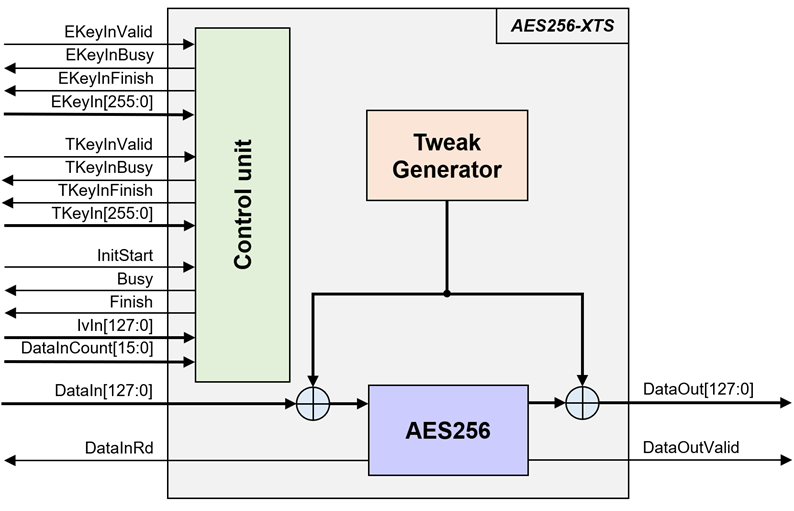
Figure 1: Block Diagram
General Description
AES256-XTS IP Core (AES256XTSIP) implement the advanced encryption standard (AES) with XEX Tweakable Block Cipher with Ciphertext Stealing (XTS) which is widely used in protecting the confidentiality of data on storage devices.
AES256XTSIP works with 256-bit encryption key and 256-bit tweakable key. According to this “ciphertext stealing” method, it can encrypt or decrypt sequences of arbitrary lengths of data block. Where the data length must be more than or equal 128 bits or 16 bytes.
AES256XTSIP consists of AES256XTSENC module which is encryption module and AES256XTSDEC module which is decryption module. which each module contains of Tweak Generator and AES256 for encryption/decryption.
Functional Description
According to AES256XTSENC and AES256XTSDEC, the interface signals and operation are the same, therefore AES256XTS is used to represent the interface signals and operation of both modules.
Table 3: Interface signals of AES256XTS
|
Signal name |
Dir |
Description |
|
RstB |
In |
IP core system reset. Active low. |
|
Clk |
In |
IP core system clock. |
|
version[31:0] |
Out |
32-bit version number of AES256XTS. |
|
Encryption Key setting signals |
||
|
EKeyInValid |
In |
EKeyInValid is a user signal to specify data valid of EKeyIn. Assert to ‘1’ to indicate that EKeyIn is valid and start encryption key setting. |
|
EKeyInBusy |
Out |
EKeyInBusy specifies busy status of encryption key setting. Assert to ‘1’ after user set EKeyInValid, until the last cycle of operation. EKeyInValid or InitStart will be ignored while EKeyInBusy is ‘1’. |
|
EKeyInFinish |
Out |
EKeyInFinish specifies finish status of encryption key setting. Assert to ‘1’ at the last cycle of operation. |
|
EKeyIn[255:0] |
In |
EKeyIn is 256-bit key data for encryption/decryption. EKeyIn must be valid when EKeyInValid is asserted to ‘1’. |
|
Tweakable Key setting signals |
||
|
TKeyInValid |
In |
TKeyInValid is a user signal to specify data valid of TKeyIn. Assert to ‘1’ to indicate that TKeyIn is valid and start tweakable key setting. |
|
TKeyInBusy |
Out |
TKeyInBusy specifies busy status of tweakable key setting. Assert to ‘1’ after user set TKeyInValid, until the last cycle of operation. TKeyInValid or InitStart will be ignored while TKeyInBusy is ‘1’. |
|
TKeyInFinish |
Out |
TKeyInFinish specifies finish status of tweakable setting. Assert to ‘1’ at the last cycle of operation. |
|
TKeyIn[255:0] |
In |
TKeyIn is 256-bit key data for encryption tweakable. TKeyIn must be valid when TKeyInValid is asserted to ‘1’. |
|
Encryption/Decryption control signals |
||
|
InitStart |
In |
InitStart is a user signal to start AES256XTS operation. |
|
Busy |
Out |
Busy specifies busy status of operation. Busy is active after user set InitStart, until operation is done. EKeyInValid or TKeyInValid or InitStart will be ignored while Busy is ‘1’. |
|
Finish |
Out |
Finish specifies finish status of AES256XTS. Assert to ‘1’ at the last cycle of operation. |
|
IvIn[127:0] |
In |
IvIn is 128-bit IV data for generate tweak. IvIn must be valid when InitStart is asserted to ‘1’. |
|
DataInCount[15:0] |
In |
DataInCount is the number of input data in byte. DataInCount must be valid when InitStart is asserted to ‘1’. |
Data control signals |
||
|
DataInRd |
Out |
DataInRd is a control signal to read DataIn. |
|
DataIn[127:0] |
In |
DataIn is 128-bit input data. DataIn must be valid when DataInRd is asserted to ‘1’. |
|
DataOutValid |
Out |
DataOutValid specifies data valid for DataOut. Assert to ‘1’ when DataOut is valid. |
|
DataOut[127:0] |
Out
|
DataOut is 128-bit data output of AES256XTS. Valid when DataOutValid is asserted to ‘1’. |
AES256XTS operation is as simple as 2 steps to use as below.
1. Key setting
Key setting is the first step to use AES256XTS. As shown in Figure 2. In the key setting process consists of encryption key setting and tweakable key setting, the two processes are completely independent of each other. AES256XTS is started encryption key setting process when EKeyInValid=‘1’ and takes 14 clocks cycles to finish the process (EKeyInBusy=‘0’). After that, this EKeyIn is used for every encryption/decryption and can be changed via EKeyInValid is asserted to ‘1’. AES256XTS is started tweakable key setting process when TKeyInValid=‘1’ and takes 14 clocks cycles to finish the process (TKeyInBusy=‘0’). After that, this TKeyIn is used for every encryption/decryption and can be changed via TKeyInValid is asserted to ‘1’.
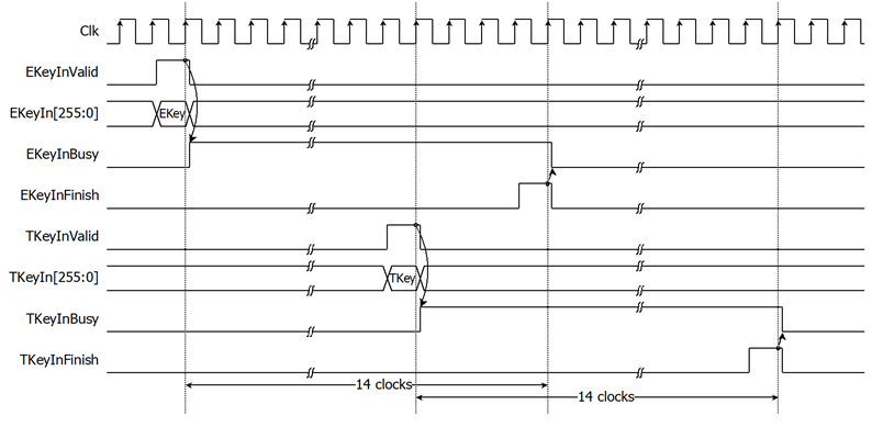
Figure 2: AES256XTS key setting timing diagram
2. Encryption/Decryption control
As shown in Figure 3 and Figure 4. After Encryption key setting process and Tweak key setting process, AES256XTS starts the process when InitStart is asserted to ‘1’ where IvIn and DataInCount must be valid. Busy is set to be ‘1’ in the next cycle. DataIn[127:0] must be set and valid when DataInRd is asserted to ‘1’. User need to prepare 128-bit DataIn. Encrypted data is set to DataOut[127:0] signal, while DataOutValid signal is set to be ‘1’. Finish is active only one clock at the last cycle of operation and DataInBusy is cleared to ‘0’ in the next cycle.
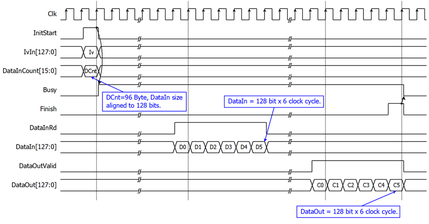
Figure 3: Example of a 96-byte data encryption/decryption timing diagram
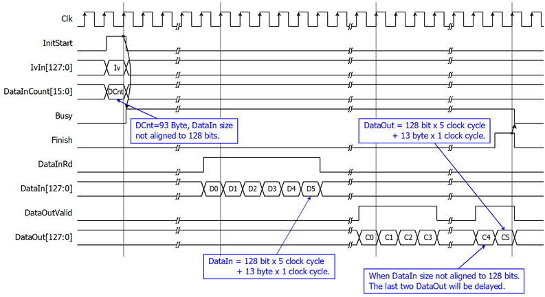
Figure 4: Example of a 93-byte data encryption/decryption timing diagram
According to DataIn has a bus size of 128 bits, it can receive data a maximum of 128 bits per clock cycle. For example, if the user wants to encrypt 31-byte data. Figure 5 shows data arrangement of 31 bytes divided into DataIn0 and DataIn1. When DataInRd is asserted to ‘1’, user must be sent DataIn0 followed by DataIn1 in the next cycle.
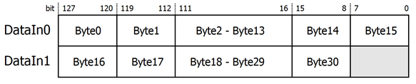
Figure 5: Data arrangement of 31 bytes for encryption/decryption
For the best performance of encryption/decryption process, Figure 6 shows timing diagram of continuous and pipelining encryption/decryption. If the user wants to encrypt with the same key as the previous operation, user can used Finish signal to generate Initstart in the next cycle for start next encryption/decryption without key setting.
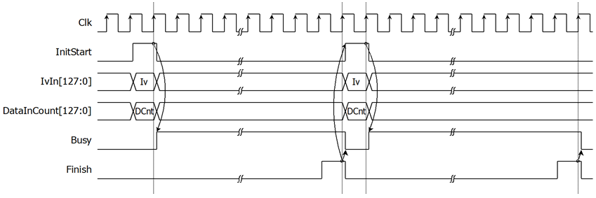
Figure 6: Timing diagram of encryption/decryption process
Verification Methods
AES256-XTS IP Core functionality were verified on real board design by using Agilex F-Series development kit and Arria10 SoC development board.
Recommended Design Experience
The user must be familiar with HDL design methodology to integrate this IP into system.
Ordering Information
This product is available directly from Design Gateway Co., Ltd. Please contact Design Gateway Co., Ltd. For pricing and additional information about this product using the contact information on the front page of this datasheet.
Revision History
|
Revision |
Date |
Description |
|
1.00 |
30/Nov/2022 |
New release |
|
1.01 |
15/Feb/2023 |
- Add feature for customized service - Add more resource information |