TOE10GLL-IP (Cut-through) Demo Instruction
2.1 Setting the IP address of the NIC
2.2 Disabling Flow Control and Interrupt Moderation.
3 Test Result Using FPGA and PC
4.3 Send Data Test (Server to Client)
4.4 Receive Data Test (Client to Server)
1 Overview
This document illustrates an example of running the TOE10GLL-IP demo using two different test environments to transfer TCP data. The first test environment employs a single FPGA board to transfer TCP data with a PC that runs a test application for transferring TCP data over 10G Ethernet. The performance result may be constrained by the resources of the PC in the specific test environment. On the other hand, the best performance for transferring TCP data using TOE10GLL-IP can be achieved by utilizing two FPGA boards in the second test environment, where they transfer data to each other.
The document covers three topics, which include setting up the 10G Ethernet connection on the PC to achieve optimal performance for transferring data via 10G Ethernet in section 2. In section 3, the console example and test results are presented when operating under the first test environment, involving FPGA and PC. Lastly, section 4 shows the console example when operating the second test environment, involving FPGA and FPGA. Each topic is described in further detail as follows.
2 PC Setup
Before running the demo, please check the network setting on your PC. The example for setting 10G Ethernet connection is described as follows.
2.1 Setting the IP address of the NIC
To set the IP address of the NIC, follow the steps below.

Figure 1 Setting IP Address of the NIC on PC
1) Open Local Area Connection Properties of the 10G Ethernet connection, as shown in the left window of Figure 1.
2) Select “TCP/IPv4” and click on Properties.
3) Set the IP address = 192.168.7.25 and the Subnet mask =
255.255.255.0, as illustrated in the right window of Figure 1.
2.2 Disabling Flow Control and Interrupt Moderation
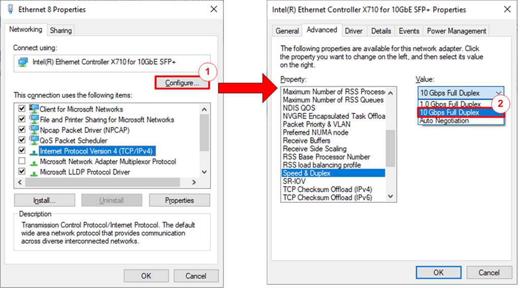
Figure 2 Flow Control Setting
1) On Local Area Connection Properties window, click on “Configure”, as shown in the left windows of Figure 2.
2) On Advanced Tab, select “Flow Control” and set Value to “Disabled”, as shown in the right windows of Figure 2.
3) Select “Interrupt Moderation” and set the value to “Disabled”, as shown in Figure 3.
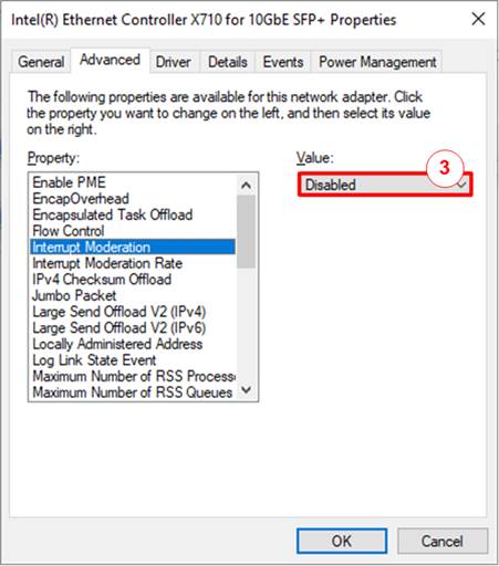
Figure 3 Interrupt Moderation Setting
4) Click the ‘OK’ button to save and exit all setting windows.
2.3 Power Option Setting

Figure 4 Power Options
1) Open Control Panel and select Power Options, as shown in the left window of Figure 4.
2) Change setting to High Performance, as shown in the right window of Figure 4.
3 Test Result Using FPGA and PC
3.1 Display TCPIP Parameters
Choose option ‘0’ to display the TCP/IP parameters. The console will show either six parameters in Client mode or seven parameters in Fixed-MAC mode.

Figure 5 Display Current Parameter Result
Here are the details of the parameters.
2) FPGA MAC address: This parameter sets the 48-bit hex value to be the MAC address of the FPGA. The default value is 0x000102030405.
3) FPGA IP: This parameter sets the IP address of FPGA. The default value is 192.168.7.42.
Note: This value is used as a Server IP address parameter for the test application on PC.
4) FPGA port number: This parameter sets the port number of the FPGA. The default value is 60000.
Note: This value is used as a Server port parameter for the test application on PC.
5) Target MAC address (displayed when running Fixed-MAC mode only): This parameter sets the 48-bit hex value as the MAC address of the target device.
· If the TOE10GLL-IP and the PC are on the same network, this is the MAC address of the target device.
· If they are in different networks, this is the MAC address of the gateway. The default value is 0x554433221100.
6) Target IP: This parameter sets the IP address of the target device (10G Ethernet on PC). The default value is 192.168.7.25.
7) Target port number: This parameter sets the port number of the target device to transfer TCP payload data. The default value is 60001.
To change any of these parameters, the user can set them by using the menu option [1] (Reset TCPIP parameters).
3.2 Reset TCPIP parameters
This menu contains six or seven parameters that must be set. Each parameter is validated before being loaded into the TOE10GLL-IP. If the input is invalid, the parameter remains unchanged. Once all parameters have been loaded, the IP is reset. The details of each parameter are described in section 3.1 (Display TCPIP Parameter), and their valid ranges are provided below.

Figure 6 Change IP Parameter Result
1) Mode: Input ‘0’ to initialize the IP as Client mode.
Note: When the PC and FPGA are connected to different networks and cannot communicate via the ARP process, the TOE10GLL-IP must be operated in Fixed-MAC mode. In this mode, the target MAC address must be manually configured to the Gateway’s MAC address via the console.
2) FPGA MAC address: Input 12 digits of hex value, prefixed by “0x” to input it as a hex value.
3) FPGA IP address: Input four decimal digits separated by “.”, where the valid range for each digit is 0-255.
4) FPGA port number: The valid range is 0-65535.
5) Target MAC address (displayed only when running Fixed-MAC mode): Input 12 digits of hex value, prefixed by “0x” to input it as a hex value.
6) Target IP address: Similar to FPGA IP address, this value is a set of four decimal digits.
7)
Target port number: The valid range is
0-65535.
After setting the parameters, the final values are displayed on the console. Then, the reset signal is sent to the IP, and it initializes using the new parameters. Finally, “IP initialization complete” is displayed on the console once the initialization process is completed, as shown in Figure 6.
3.3 Send Data Test
Choose option ‘2’ from the menu to send data from an FPGA to a PC. The test application, “tcpdatatest.exe”, is called on the PC with specified parameters via Command prompt for receiving data. Simultaneously, the user inputs the test parameters for sending data on the FPGA console. The steps to run the test are outlined below.
1) On the FPGA console, input four parameters to initiate the Send data test.
· Transfer size: The transfer size is specified in bytes. The valid range is 1 - 0xFFFF_FFFF_FFFF. If inputting a decimal number, enter the digits. For hexadecimal values, prefix the input with “0x”.
· Packet size: The packet size is specified in bytes. The valid range is 1 – 1460. Similar to the transfer size, decimal values can be entered directly, while hexadecimal values must be prefixed with “0x”.
· Enable PSH: TCP flag to inform that the destination device should return acknowledgement packet for the latest transmitted data immediately. Input ‘0’ to disable PSH flag or ‘1’ to enable PSH flag.
· Mode: This is the connection mode for the FPGA. Input ‘1’ to open connection in Server mode (Passive open).
2) If all inputs are valid, the recommended parameters to run test application on the PC will be displayed. The FPGA console will then display “Wait Open connection …”, indicating it is waiting for a connection establishment request from the PC application.
3) On the Command prompt, input the test parameters following the recommended values. The “tcpdatatest” application requires six parameters.
>> tcpdatatest <mode> <dir> <server IP> <server port> <bytelen> <pattern>
· Mode : Input ‘c’ to run the PC as a Client.
· Dir : Input ‘r’ to run the PC for receiving and verifying test data from the FPGA.
· Server IP : Input the local IP address of the FPGA.
· Server port : Input the local port number of the FPGA.
· Bytelen : Input the same value as “Input transfer size” of step (1).
· Pattern : Input ‘1’ to enable data verification from the FPGA or ‘0’ to skip verification.
4) After running the test application on the PC, the port is created and the current amount of transferred data is displayed on both the FPGA console (transmitted data) and the Command prompt (received data) every second. Once the FPGA completes the transfer, it will close the connection, and the message “Send data complete” will be displayed on the console.
5) Finally, the total transfer size and performance are displayed on the console (transmit performance) and Command prompt (receive performance). In addition, the data transmission latency of the TOE10GLL-IP is displayed on the console.
Figure 7 shows an example of the Send data test with basic settings, involving the transmission of packets and enabling data verification on the test application. The left window displays the FPGA console operating as Server-connection, while the right window displays the Command prompt on the PC operating as Client-connection.
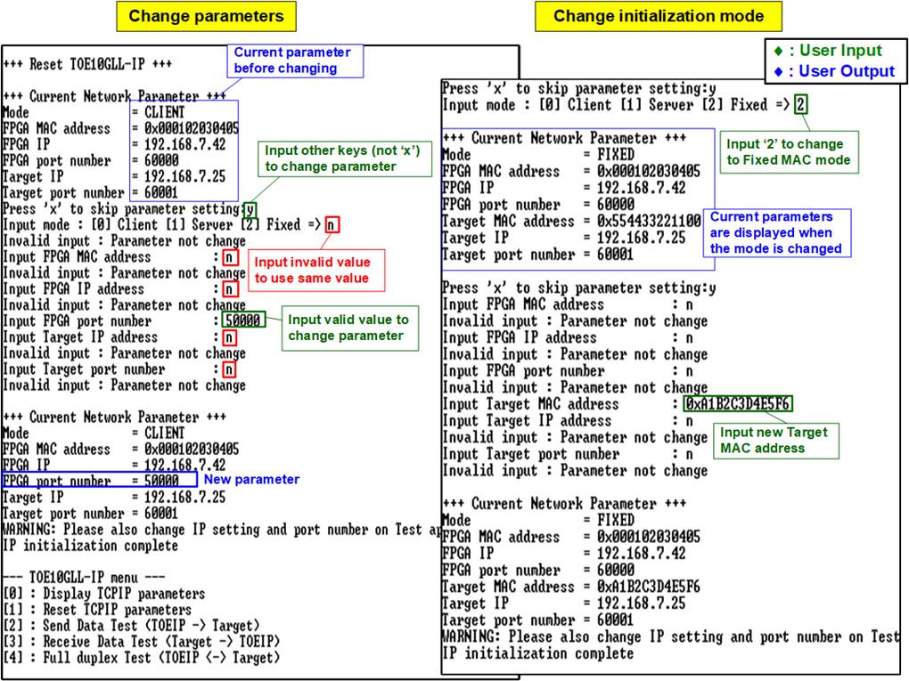
Figure 7 Send Data Test (Cut-Through Mode)
If the input is invalid, an error message: “Out-of-range input” or “Invalid input” will be displayed. After that, the operation is cancelled, as shown in Figure 8 - Figure 11.
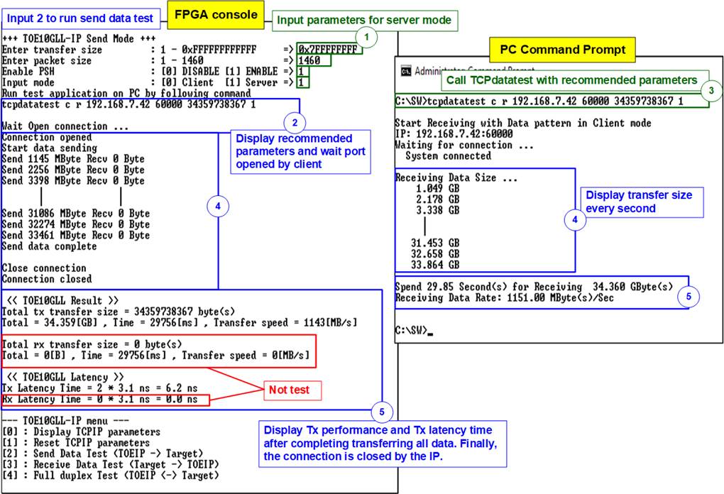
Figure 8 Error from Invalid Transfer Size

Figure 9 Error from Invalid Packet Size

Figure 10 Error from Invalid PSH Value

Figure 11 Error from Invalid Mode
3.4 Receive Data Test
Choose option ‘3’ from the menu to receive data sent from a PC to an FPGA. The test application, “tcpdatatest.exe”, is executed on the PC with specified parameters via Command prompt for sending data. Simultaneously, the user inputs the test parameters for receiving and verifying data on the FPGA console. The steps to run the test are outlined below.
1) On the FPGA console, input three parameters to initiate the Receive data test.
· Transfer size: The transfer size is specified in bytes. The valid range is 1 - 0xFFFF_FFFF_FFFF. If inputting a decimal number, enter the digits. For hexadecimal values, prefix the input with “0x”.
· Data verification mode: Set to ‘0’ to disable data verification or ‘1’ to enable data verification to verify data sent from the PC.
· Mode: This is the connection mode of the FPGA. Input ‘1’ to open connection in Server mode (Passive open).
2) If all inputs are valid, the recommended parameters to run the test application on the PC will be displayed. The FPGA console will then display “Wait Open connection …”, indicating it is waiting for a connection establishment request from the PC application.
3) On the Command prompt, input the test parameters following the recommended value. The “tcpdatatest” application requires six parameters.
>> tcpdatatest <mode> <dir> <server IP> <server port> <bytelen> <pattern>
· Mode : Input ‘c’ to run the PC as a Client.
· Dir : Input ‘t’ to run the PC for sending test data to the FPGA
· Server IP : Input the local IP address of the FPGA
· Server port : Input the local port number of the FPGA
· Bytelen : Input the same value as the “Transfer size” from step (1)
· Pattern : Input the same value as the “Data verification mode” from step (1). Select ‘0’ to send dummy data or ‘1’ to send incremental data.
4) After running the test application on the PC, a port is created, and the current amount of transferred data is displayed on both the FPGA console (received data) and the Command prompt (transmitted data) every second.
5) Once the PC completes the transfer, it will close the connection. The FPGA console will display “Connection closed” and “Received data completed”. Finally, the total transfer size and performance are displayed on the FPGA console (receive performance) and the Command prompt (transmit performance). In addition, the data reception latency of the TOE10GLL-IP is displayed on the console.
Figure 12 shows an example of a Receive data test with the basic settings of the “tcpdatatest” application on a PC. The application activates incremental data generation. The left window displays the FPGA console (Client-connection), while the right window displays the Command prompt on PC (Server-connection).
In the specific test environment, maximum performance in the Receive data test can be achieved by disabling incremental data generation and transmitting dummy data, as illustrated in Figure 13. Additionally, data verification must be disabled on the FPGA during dummy data reception.

Figure 12 Receive Data Test with Normal settings
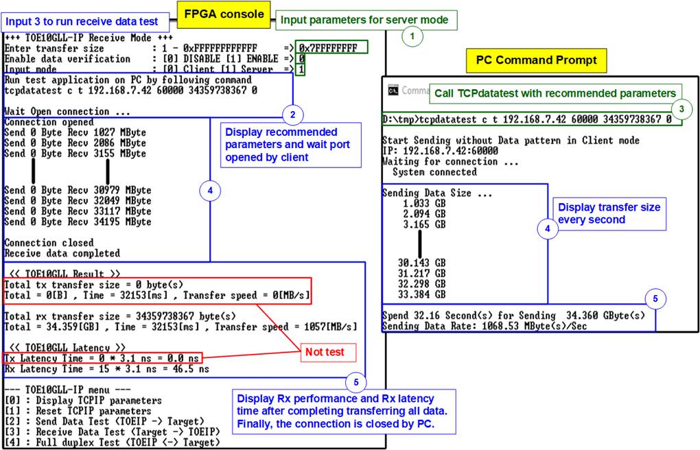
Figure 13 Receive Data Test with Disabling Data Verification
Figure 14 provides an error example resulting from data verification failure. The error is caused by a mismatch between the verification mode values of the FPGA and the PC. The FPGA enables data verification, while the “tcpdatatest” application is configured to send dummy data. The error message is displayed on the FPGA console.

Figure 14 Data Verification Failure During Receive Data Test
3.5 Full Duplex Test
1) On the FPGA console, the user must input five parameters to initiate the full-duplex test.
· Transfer size: The transfer size is specified in bytes. The valid range is 1 - 0xFFFF_FFFF_FFFF. If inputting a decimal number, enter the digits. For hexadecimal values, prefix the input with “0x”.
· Packet size: The packet size is specified in bytes. Similar to the transfer size, decimal values can be entered directly, while hexadecimal values must be prefixed with “0x”.
· Enable PSH: TCP flag to inform that the destination device should return acknowledgement packet for the latest transmitted data immediately. Input ‘0’ to disable PSH flag or ‘1’ to enable PSH flag.
· Data verification mode: Set to ‘0’ to disable data verification or ‘1’ to enable data verification to verify data sent from the PC.
· Mode: This is the connection mode for the FPGA. Input ‘1’ to open connection in Server mode (Passive open).
2) If all inputs are valid, the recommended parameters to run the test application on the PC will be displayed. The FPGA console will then display “Wait Open connection …”, indicating it is waiting for a connection establishment request from the PC application.
3) On the Command prompt, input the test parameters following the recommended values. The “tcp_client_txrx_xg” application requires four parameters.
>> tcp_client_txrx_xg <server IP> <server port> <bytelen> <pattern>
· Server IP : Input the local IP address of the FPGA
· Server port : Input the local port number of the FPGA
· ByteLen : Input the same value as the “Transfer size” from step (1).
· Pattern : Input the same value as the “Data verification mode” from step (1).
- ‘0’ to send dummy data and do nothing with the received data.
- ‘1’ to send incremental data and verify the received data.
4) After running the test application on the PC, the port is created, and the current amount of transferred data is displayed on both FPGA console and Command prompt every second.
5) Once the PC (the Client) completes the transfer in both directions, it will close the connection. Finally, the total transfer size and performance are displayed on the FPGA console and Command prompt. In addition, the bidirectional data latency of the TOE10GLL-IP is displayed on the console.
There is a two-second time gap after step (5) for user to stop the operation by pressing any key on FPGA console and then entering ‘Ctrl+C’ on Command prompt. Otherwise, the process repeats steps (4) – (5) in a continuous loop.
Examples of running full-duplex tests with and without data verification are illustrated in Figure 15 and Figure 16, respectively. In specific test environment, disabling data verification shows better overall performance than enabling it. The FPGA console operates as Client-connection in the left window, while the Command prompt on the PC functions as a Server-connection in the right window.
As shown in Figure 16, the sending performance measured on the FPGA console is higher than the receiving performance measured on the PC console. This difference arises because the test application calculates performance based on the total time for both sending and receiving, whereas the FPGA calculates sending and receiving performance separately.

Figure 15 Full Duplex Test with Enabling Data Verification
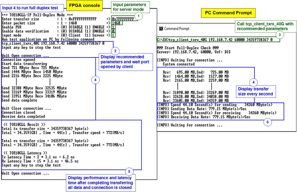
Figure 16 Full Duplex Test with Disabling
Data Verification
3.6 Ping Test
For the Ping command test, the user initiates the test by entering the ping <FPGA IP address> command in the Command Prompt. The PC generates an ICMP Echo Request, and the FPGA responds with an ICMP Echo Reply. The measured round-trip time is then displayed in the Command Prompt, as shown in Figure 17
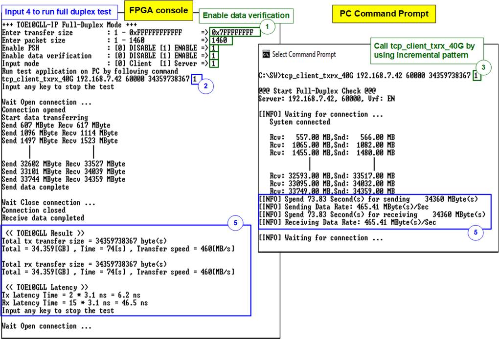
Figure 17 Ping Command Result on PC
4 Test Result Using Two FPGAs
4.1 Display TCPIP Parameters

Figure 18 Display Current Parameter Result
Here are the details of the parameters.
1) Mode: This parameter sets the mode of the TOE10GLL-IP to initialize in Server, Client, or Fixed-MAC. Input ‘0’ for Client, ‘1’ for Server, or ‘2’ for Fixed-MAC.
2) FPGA MAC address: This parameter sets the 48-bit hex value as the MAC address of the FPGA. The default value is 0x000102030405 (Client mode/Fixed-MAC mode) or 0x001122334455 (Server mode).
3) FPGA IP: This parameter sets the IP address of the FPGA. The default value is 192.168.7.42 (Client mode/Fixed-MAC mode) or 192.168.7.25 (Server mode).
4) FPGA port number: This parameter sets the port number of the FPGA. The default value is 60000 (Client mode/Fixed-MAC mode) or 60001 (Server mode).
5) Target MAC address (displayed when running Fixed-MAC mode only): This parameter sets the 48-bit hex value as the MAC address of the target device.
· If the two FPGAs are on the same network, this is the MAC address of the target device.
· If they are in different networks, this is the MAC address of the gateway. The default value is 0x554433221100.
6) Target IP: This parameter sets the IP address of the target device. The default value is 192.168.7.25 (Client mode) or 192.168.7.42 (Server mode).
7) Target port number: This parameter sets the port number of the target device to transfer TCP payload data. The default value is 60001 (Client MAC mode/Fixed-MAC mode) or 60000 (Server mode).
To change any of these parameters, the user can set them using the menu option [1] (Reset TCPIP parameters).
4.2 Reset TCPIP Parameters
Choose option ‘1’ from the menu to reset the IP and modify IP parameters. This menu allows the user to change the IP settings or reset the TOE10GLL-IP. Upon selection of this option, the current parameters are displayed on the console. Press ‘x’ to keep the same parameters, or press any other key to modify them. Once the parameters are confirmed, the TOE10GLL-IP is reset and the initialization process begins.
This menu contains eight or nine parameters that must be set. Each parameter is validated before being loaded into the TOE10GLL-IP. If the input is invalid, the parameter remains unchanged. Once all parameters have been loaded, the IP is reset. The details of each parameter are described in section 4.1 (Display TCPIP Parameter), and their valid ranges are provided below.
Note:
· Ensure that two FPGA devices are configured using supported initialization mode pairs: Server <–> Client (same network domain only), Client <–> Fixed-MAC (same network domain only), or Fixed-MAC <-> Fixed-MAC.
· When operating in Server <-> Client mode, if the parameters on the Server need to be reset, the Client FPGA must also be reset. Additionally, the Server must be reset before the Client to ensure that it waits until the ARP request is sent by the Client.
· It is essential to match the parameters of both FPGAs as listed below.
· The Target IP address of board#1 = The FPGA IP address of board#2
· The FPGA IP address of board#1 = The Target IP address of board#2
· The Target port number of board#1 = The FPGA port number of board#2
· The FPGA port number of board#1 = The Target port number of board#2
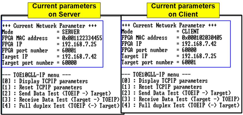
Figure 19 Change IP Parameter Result
for Server/Client Mode

Figure 20 Change IP Parameter Result for Fixed-MAC Mode
1) Mode: Input ‘0’ (Client), ‘1’ (Server), ‘2’ (Fixed-MAC) to determine FPGA initialization mode.
2) FPGA MAC address: Input 12 digits of hex value, prefixed by “0x” to input it as a hex value.
3) FPGA IP address: Input four decimal digits separated by “.”, where the valid range for each digit is 0-255.
4) FPGA port number: The valid range is 0-65535.
5) Target MAC address (displayed only when running Fixed-MAC mode): Input 12 digits of hex value, prefixed by “0x” to input it as a hex value.
6) Target IP address: Similar to FPGA IP address, this value is a set of four decimal digits.
7) Target port number: The valid range is 0-65535.
After setting the parameters, the final values are displayed on the console. Then, the reset signal is sent to the IP, and it initializes using the new parameters. Finally, “IP initialization complete” is displayed on the console once the initialization process is complete, as shown in Figure 19 and Figure 20.
4.3 Send Data Test (Server to Client)
To transmit data from the Server-connection FPGA to the Client-connection FPGA, choose option ‘2’ to initiate the Send data test on the Server-connection FPGA, and select option ‘3’ to initiate the Receive data test on the Client-connection FPGA. The user sets test parameters on both FPGA consoles. The test sequence is outlined below.
Note: The modes configured in the Send Data Test, Receive Data Test, and Full Duplex Test, for communication between two FPGAs determine how the connection is opened and closed. These modes can be configured as active mode (Client) or passive mode (Server). However, this setting is not related to the initialization mode, which is used to configure the FPGAs as a Client or Server mode. It is important to set the two FPGAs to different connection modes, with one being set as the Client and the other as the Server.
1) On the Server-connection console, input four parameters to initiate the Send data test.
· Transfer size: The transfer size is specified in bytes. The valid range is 1 - 0xFFFF_FFFF_FFFF. If inputting a decimal number, enter the digits. For hexadecimal values, prefix the input with “0x”.
· Packet size: The packet size is specified in bytes. The valid range is 1 – 1460. Similar to the transfer size, decimal values can be entered directly, while hexadecimal values must be prefixed with “0x”.
· Enable PSH: TCP flag to inform that the destination device should return acknowledgement packet for the latest transmitted data immediately. Input ‘0’ to disable PSH flag or ‘1’ to enable PSH flag.
· Mode: This is the connection mode for the FPGA. Input ‘1’ to open connection in Server mode (Passive open).
2) If all inputs are valid, the Server-connection console displays “Wait Open connection …”, indicating it is waiting for the Client-connection FPGA to initiate the connection establishment. If any inputs are invalid, the console displays “Out-of-range input” or “Invalid input”, and the operation will be cancelled, similar to PC-based test (as shown in Figure 8 - Figure 11).
3) On the Client-connection console, input three parameters to initiate the Receive data test.
· Transfer size: The transfer size is specified in bytes. The valid range is 1 - 0xFFFF_FFFF_FFFF. If inputting a decimal number, enter the digits. For hexadecimal values, prefix the input with “0x”. Input the same value as “Transfer size” from step (1).
· Data verification mode: Set to ‘0’ to disable data verification or ‘1’ to enable data verification to verify data sent from the Server FPGA.
· Mode: This is the connection mode for the FPGA. Input ‘0’ to open connection in Client mode (Active open).
4) Once all inputs are valid, the operation begins. The port is created and the console displays the current transfer size on both consoles every second. After sending all data, “Send data complete” is displayed on the Server-connection console.
5) The Server-connection FPGA then closes the connection, and the total transfer size and performance are displayed on both consoles.
In Figure 21 the Server-connection console is displayed on the left window, while the right window displays the Client-connection console. This example demonstrates the performance of the Send data test.

Figure 21 Send Data Test (2-FPGA Test Environment)
4.4 Receive Data Test (Client to Server)
This section describes the steps for transferring data from the Client-connection FPGA to the Server-connection FPGA. The Server-connection FPGA must be initiated by choosing option ‘3’ to run Receive data test before entering option ‘2’ to initiate the Send data test at the Client-connection FPGA. The test sequence is outlined below.
1) On the Server-connection console, input three parameters to initiate the Receive data test.
· Transfer size: The transfer size is specified in bytes. The valid range is 1 - 0xFFFF_FFFF_FFFF. If inputting a decimal number, enter the digits. For hexadecimal values, prefix the input with “0x”.
· Data verification mode: Set to ‘0’ to disable data verification or ‘1’ to enable data verification to verify data sent from the Client FPGA.
· Mode: This is the connection mode for the FPGA. Input ‘1’ to open connection in Server mode (Passive open).
2) If all inputs are valid, the Server-connection console will then display “Wait Open connection …”, indicating it is waiting for the Client FPGA to initiate the connection establishment.
3) On the Client-connection console, input four parameters to initiate the Send data test.
· Transfer size: The transfer size is specified in bytes. The valid range is 1 - 0xFFFF_FFFF_FFFF. If inputting a decimal number, enter the digits. For hexadecimal values, prefix the input with “0x”. Input the same value as “Transfer size” from step (1).
· Packet size: The packet size is specified in bytes. The valid range is 1 – 1460. Similar to the transfer size, decimal values can be entered directly, while hexadecimal values must be prefixed with “0x”.
· Enable PSH: TCP flag to inform that the destination device should return acknowledgement packet for the latest transmitted data immediately. Input ‘0’ to disable PSH flag or ‘1’ to enable PSH flag.
· Mode: This is the connection mode for the FPGA. Input ‘0’ to open connection in Client mode (Active open).
4) Once all inputs are valid, the operation begins. The port is created and the console displays the current transfer size on both consoles every second. After sending all data, “Send data complete” is displayed on the Client-connection console.
5) The Client-connection FPGA then closes the connection, and the total transfer size and performance are displayed on both consoles.
The left window in Figure 22 shows the Server-connection console, and the right window displays the Client-connection console.
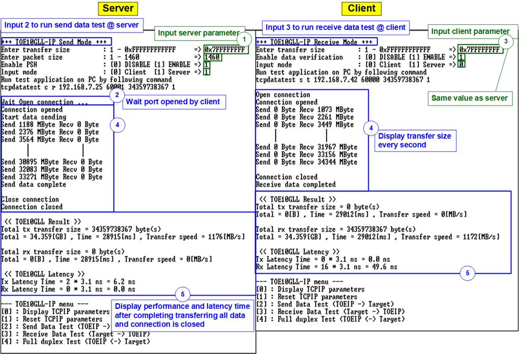
Figure 22 Receive Data Test with Data Verification (2-FPGA Test Environment)
4.5 Full Duplex Test
Choose option ‘4’ to transfer data simultaneously in both directions and run a full-duplex test on both the Server-connection FPGA and the Client-connection FPGA. The user sets test parameters on both FPGA consoles. The following sequence illustrates how to run the test.
1) On the Server-connection console, input five parameters to initiate the full-duplex test.
· Transfer size: The transfer size is specified in bytes. The valid range is 1 - 0xFFFF_FFFF_FFFF. If inputting a decimal number, enter the digits. For hexadecimal values, prefix the input with “0x”.
· Packet size: The packet size is specified in bytes. The valid range is 1 – 1460. Similar to the transfer size, decimal values can be entered directly, while hexadecimal values must be prefixed with “0x”.
· Enable PSH: TCP flag to inform that the destination device should return acknowledgement packet for the latest transmitted data immediately. Input ‘0’ to disable PSH flag or ‘1’ to enable PSH flag.
· Data verification mode: Set to ‘0’ to disable data verification or ‘1’ to enable data verification to verify data sent from the Client-connection FPGA.
· Mode: This is the connection mode for the FPGA. Input ‘1’ to open connection in Server mode (Passive open).
2) If all inputs are valid, the Server-connection console will then display “Wait Open connection …”, indicating it is waiting for the Client-connection FPGA to initiate the connection establishment.
3) On the Client console, input five parameters to initiate the full-duplex test.
· Transfer size: The transfer size is specified in bytes. The valid range is 1 – 0xFFFF_FFFF_FFFF. If inputting a decimal number, enter the digits. For hexadecimal values, prefix the input with “0x”. Input the same value as “Transfer size” from step (1).
· Packet size: The packet size is specified in bytes. The valid range is 1 – 1460. Similar to the transfer size, decimal values can be entered directly, while hexadecimal values must be prefixed with “0x”.
· Enable PSH: TCP flag to inform that the destination device should return acknowledgement packet for the latest transmitted data immediately. Input ‘0’ to disable PSH flag or ‘1’ to enable PSH flag.
· Data verification mode: Set to ‘0’ to disable data verification or ‘1’ to enable data verification to verify data sent from the Server-connection FPGA.
· Mode: This is the connection mode for the FPGA. Input ‘0’ to open connection in Client mode (Active open).
4) Once all inputs are valid, the operation begins. The port is created and both consoles display the current transfer size of both transfer directions every second.
5) After completing data transfer in both directions, the Client-connection FPGA closes the connection. Both consoles display the total transfer size, achieved performance, and data latency of TOE10GLL-IP.
There is a two-second time gap after step (5) for the user to stop the operation by pressing any key on both consoles. Otherwise, the operation repeats step (4) – (5) in a continuous loop.
Figure 23 illustrates a full-duplex test between two FPGAs. The left window shows the Server-connection console, while the right window displays the Client-connection console.
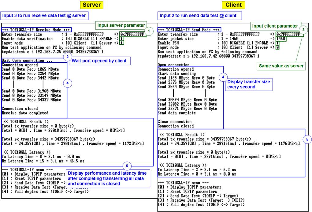
Figure 23 Full Duplex Test with Data Verification (2-FPGA Test Environment)
5 Revision History
|
Revision |
Date (D-M-Y) |
Description |
|
1.02 |
8-Jan-26 |
Update the test result using ‘tcp_client_txrx_xg’ application. |
|
1.01 |
4-Apr-22 |
Update latency time and add Ping test |
|
1.00 |
20-Nov-20 |
Initial version release |