NVMeG4-IP with DMA on PetaLinux Demo Instruction
1 Overview
This document provides comprehensive instructions for demonstrating high-speed DMA data transfers between an NVMe Gen4 SSD and main memory using the NVMeG4-IP core from Design Gateway on a PetaLinux-based FPGA system. The demonstration environment is booted from an SD card and controlled via a Serial console. Users interact with the system through a terminal interface, issuing commands to perform various NVMe operations. The demo supports seven commands: Identify, Write, Read, SMART, Flush, Secure Erase, and Shutdown. These operations are executed through a dedicated test application named “dgnvme”, which highlights the full data transfer performance of the NVMe Gen4 SSD – reaching speeds of up to 6900 MB/s for write operations and 7500 MB/s for read operations.
To begin the demo, users must first prepare the hardware according to the setup instructions provided in the “NVMeG4IP-dmalinux-fpgasetup-amd” document. This setup process includes hardware connection, SD card preparation, and FPGA configuration. Once the FPGA has fully booted from the SD card, a login screen will appear on the Serial console, as illustrated Figure 1. Users enter “root” for both the username and password to log into the Linux system.
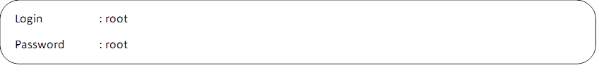
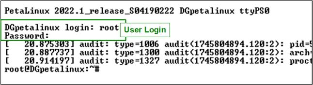
Figure 1 Log-in Window
Upon successful login, users can launch the test application by entering the command “dgnvme” at the terminal prompt. This initiates the demonstration, enabling execution of various NVMe commands and real-time monitoring of the system’s performance through the Serial console. Overall, this overview introduces how to evaluate the capabilities of the NVMeG4-IP under PetaLinux. It provides not only insights into achievable performance but also a practical guide for operating the test application in an FPGA-based environment.
2 Test Application
Before running the test application, it is important to verify that the NVMe Gen4 driver module and the NVMe Gen4 device has been properly installed and initialized. This can be done using the “lsmod” command, as illustrated in Figure 2.
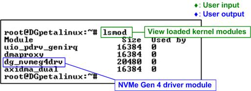
Figure 2 Drivers Loaded in the System
The “lsmod” command lists all kernel modules currently loaded into the system. Users should check for the presence of the “dg_nvmeg4drv” module, which indicates that the device for the NVMe Gen4 interface has been successfully loaded.
Once the driver is confirmed to be active, users can execute the “ls /dev/dgnvme*” command to list the device nodes created by the driver. This command searches for device files that match the “dgnvme” naming pattern.
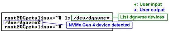
Figure 3 NVMe Device Detected
If the NVMe Gen4 device has been correctly detected and initialized, the console will display a device node – “/dev/dgnvme0”, indicating that the system is ready to perform NVMe operations.
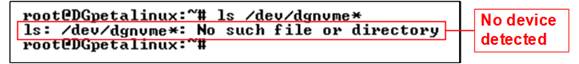
Figure 4 NVMe Device Not Detected
However, if the NVMe Gen4 device fails to initialize or is not properly connected, the command will return an error message: “ls: /dev/dgnvme*: No such file or directory”. In such cases, users should recheck the hardware setup to resolve the issue before proceeding.
Once the NVMe Gen4 device is successfully initialized, users can proceed to run the test application “dgnvme”, which is used to execute various NVMe commands supported by the NVMeG4-IP core. A list of supported commands can be viewed by running “dgnvme help”, as shown in Figure 5.

Figure 5 Help Command
· <command>: Specifies the operation to be performed on the NVMe device. Supported commands include:
· identify : Displays device identification data in either decoded or raw format.
· write : Writes data to the device.
· read : Reads data from the device.
· smart : Displays SMART health information.
· flush : Forces cached data to be written to the device.
· secure-erase : Issues a Secure Erase command.
· shutdown : Safely powers down the device.
· help : Displays usage information and available options for each command.
· <device>: Specifies the NVMe device file to be accessed. In this demo, the driver is preloaded into the Linux kernel, so no manual insertion is required. The device can typically be accessed via “/dev/dgnvme0”.
[options]: Additional parameters that may be required depending on the command. Some commands support multiple options such as operation modes, offsets, or lengths. These parameters allow users to customize the behavior of the command. For detailed information about the available options, enter “dgnvme help <command>”. For example, “dgnvme help identify” displays all supported options for the Identify command.
2.1 Identify Command

Figure 6 Identify Command Options
The Identify command is used to retrieve identification data from the NVMe device. As shown in Figure 6, this command provides two output formats for displaying the retrieved data.
Decoded Output Format
The decoded format presents the identify data in a human-readable structure. It extracts and displays key information about the NVMe device, as illustrated in Figure 7.
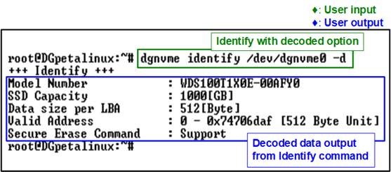
Figure 7 Decoded Mode of Identify Command
The displayed information includes:
· Model Number: Decoded from the Identify Controller data, indicating the model of the device.
· SSD Capacity: Provided by the NVMeG4-IP, indicating the total usable storage capacity of the device.
· Data size per LBA: Provided by the NVMeG4-IP, indicating the size of each logical block address (LBA), either 512 bytes or 4 KB, depending on the device configuration.
· Valid Address: Provided by the NVMeG4-IP, showing the highest valid address that can be accessed by the host.
· Secure Erase Command: Decoded from the Identify Controller data, indicating whether the device supports the Secure Erase feature.
Raw Data Format
The raw format displays the identify data as a hexadecimal output. This command format is:
>> identify -r <byte_addr> <nbytes>
The “byte_addr” specifies the starting address in bytes, and the “nbytes” defines the number of bytes to be read.
The total amount of data retrievable with this command is 8 KB. The first 4KB contains the “Identify Controller Data Structure”, while the remaining 4KB contains the “Identify Namespace Data Structure”. Therefore, the sum of “byte_addr” and “nbytes” must not exceed 8192 bytes. If this limit is exceeded, the command will return an error message.

Figure 8 Raw Data Mode of Identify Command
2.2 Write Command

Figure 9 Write Command Options
The Write command is used to transfer data from main memory to the NVMe device. It requires three input parameters, as shown below:
>> dgnvme write <device> -m <patt_mode> -a <block_addr> -l <block_len>
· <patt_mode> : Specifies the test data pattern to be generated in main memory for the write operation. Supported modes include:
· perf : Performance mode using dummy data (optimized for speed).
· one : Writes a pattern of all 1s.
· zero : Writes a pattern of all 0s.
· inc : Writes a 32-bit incremental data pattern.
· dec : Writes a 32-bit decremental data pattern.
· <block_addr> : Specifies the starting address on the device where the write operation begins, specified in units of 512 bytes.
· <block_len> : Specifies the amount of data to be written, specified in units of 512 bytes.
Note: The sum of “block_addr” and “block_len” must not exceed the total device capacity. This capacity can be confirmed using the output of the Identify command or by referencing the usage information provided by “dgnvme help write <device specified>”.

Figure 10 Write Command with Performance Mode
Once the required parameters are validated, the write process begins. During execution, the console provides real-time updates every second, showing the percentage of data written, current transfer speed in MB/s, and elapsed time in seconds. After the operation is complete, the application displays a summary that includes the total amount of data transferred, the average transfer speed, and the total time taken for the operation.
As shown in Figure 10, the system achieves maximum write bandwidth when using performance mode (-m perf), where the CPU does not generate any data pattern. This allows the system to fully utilize high-speed DMA transfers without CPU involvement, resulting in optimal throughput.
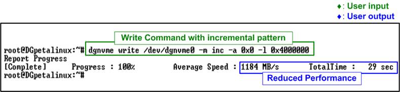
Figure 11 Write Command with 32-Bit Incremental Data Pattern
In contrast, Figure 11 illustrates the write command executed in incremental pattern mode. In this mode, the CPU is responsible for generating and preparing all the data before it is written to the device. This additional processing introduces overhead, which typically results in reduced performance compared to the performance mode, where data is transferred directly via DMA without CPU involvement.
2.3 Read Command

Figure 12 Read Command Options
The Read command is used to transfer data from the NVMe device to main memory. It requires two or three input parameters, depending on the selected mode, as shown below:
>> dgnvme read <device> -m <patt_mode> -a <block_addr> [-l <block_len>]
· <patt_mode> : Specifies the test data pattern used for verifying the data in main memory after the read operation. Supported modes include:
· perf : Performance mode that reads data without verification (optimized for speed).
· one : Reads and verifies with a pattern of all 1s.
· zero : Reads and verifies with a pattern of all 0s.
· inc : Reads and verifies with a 32-bit incremental data pattern.
· dec : Reads and verifies with a 32-bit decremental data pattern.
· dump : Reads and displays the retrieved data in the console.
· <block_addr> : Specifies the starting address on the device where the read operation begins, specified in units of 512 bytes.
· <block_len> (optionsl) : Specifies the amount of data to be read, specified in units of 512 bytes. This parameter is required for all modes except “dump”.
Note: The sum of “block_addr” and “block_len” must not exceed
the total device capacity. This capacity can be confirmed using the output of
the Identify command or by referencing the usage information provided by
“dgnvme help read <device specified>”.
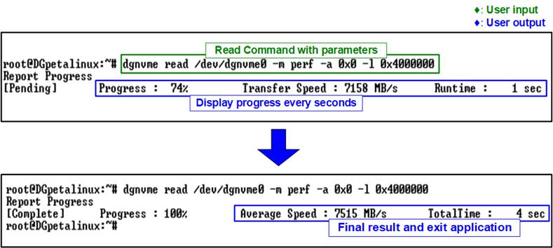
Figure 13 Read Command with Performance Mode
Once the required parameters are validated, the read process begins. During execution, the console provides real-time updates every second, showing the percentage of data read, current transfer speed in MB/s, and elapsed time in seconds. After the operation is complete, the application displays a summary that includes the total amount of data transferred, the average transfer speed, and the total time taken for the operation.
As shown in Figure 13, the system achieves maximum read bandwidth when using performance mode (-m perf), where the CPU does not verify the read data. This enables the system to fully utilize high-speed DMA transfers without CPU involvement, resulting in optimal throughput.
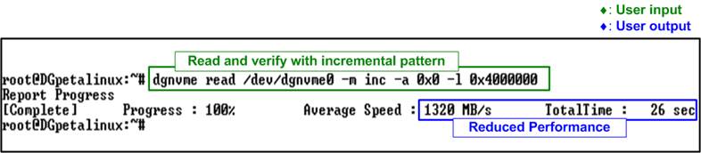
Figure 14 Read Command with 32-Bit Incremental Data Pattern
In contrast, Figure 14 illustrates the read command executed in incremental pattern mode (-m inc), where the CPU must verify all data read from the device. This additional processing step introduces overhead, which typically reduces overall performance compared to performance mode.
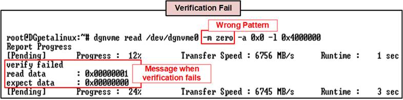
Figure 15 Read Command with Verify Failed
In the event of a data verification failure during the Read command, an error message is displayed on the console, as shown in Figure 15. The message “verify failed” appears, along with additional details indicating the expected value and the actual value read from the device.
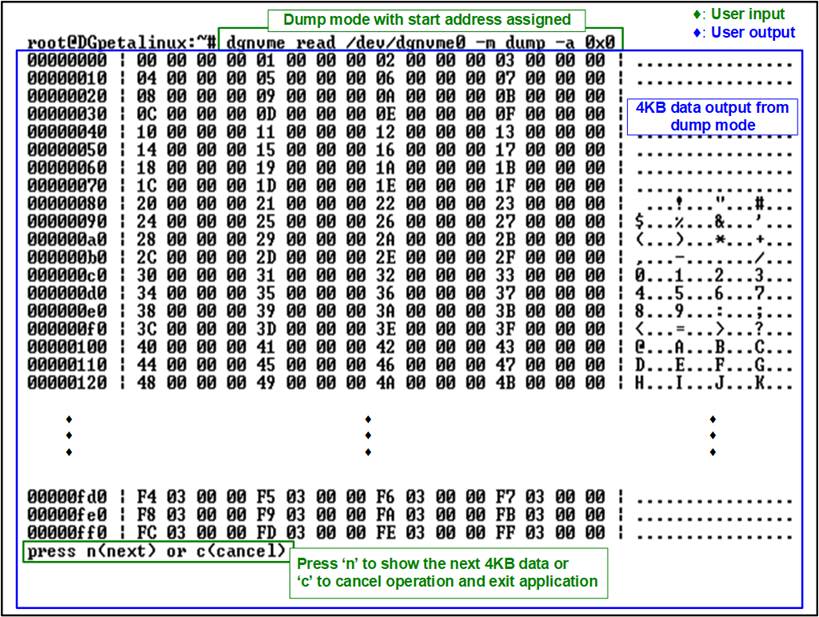
Figure 16 Dump Mode of Read Command
Figure 16 shows the console output when executing the Read command in dump mode (-m dump). Once the required parameters are validated, the read process begins with a fixed length of 64 MB. The retrieved data is displayed in 4 KB blocks directly in the console. During the operation, the user is prompted to press 'n' to continue displaying the next 4 KB block or 'c' to cancel and exit the application.
2.4 SMART Command

Figure 17 SMART Command Options
The SMART command is used to retrieve health and diagnostic information from the NVMe device. As shown in Figure 17, this command provides two output formats for displaying the retrieved data, similar to Identify command.
Decoded Output Format
The decoded format presents the SMART data in a human-readable structure. It extracts and displays health information of NVMe device, as illustrated in Figure 18.
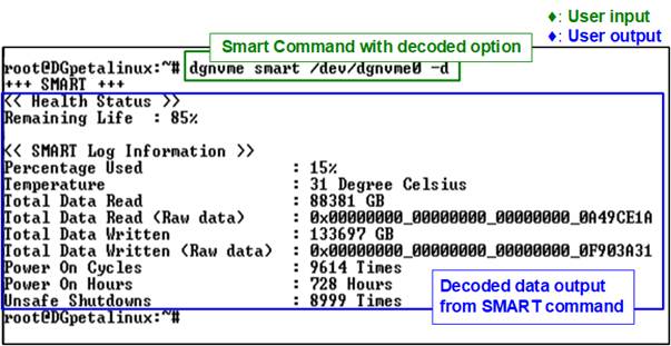
Figure 18 SMART Command Decoded Mode
The Health status displays the remaining life of the device as a percentage, derived from the “Percentage Used” value in the SMART log. The following seven parameters are included in the decoded SMART data:
· Percentage used : Indicates the portions of the device’s lifespan that has been consumed, expressed as a percentage.
· Temperature : Displays the current operating temperature of the device in degrees Celsius.
· Total Data Read : Shows the cumulative amount of data read from the device, displayed in GB/TB units. The raw data is also provided as a 32-digit hex number (128 bits), where each unit represents 512,000 bytes.
· Total Data Written : Shows the cumulative amount of data w written to the device, displayed in GB/TB units. The raw data is also provided as a 32-digit hex number (128 bits), where each unit represents 512,000 bytes.
· Power On Cycles : Reports the total number of times the device has been powered on.
· Power On Hours : Reports the total amount of hours the device has been powered on.
· Unsafe Shutdowns : Represents the number of times the device has experienced an unsafe shutdown.
Raw Data Format
The raw format displays the SMART data as a hexadecimal output. This command format is:
>> smart -r <byte_addr> <nbytes>
The “byte_addr” specifies the starting address in bytes, and the “nbytes” defines the number of bytes to be read.
The total amount of data retrievable with this command is 512 bytes. Therefore, the sum of “byte_addr” and “nbytes” must not exceed 512 bytes. If this limit is exceeded, the command will return an error message.

Figure 19 Raw Data Mode of SMART Command
2.5 Flush Command
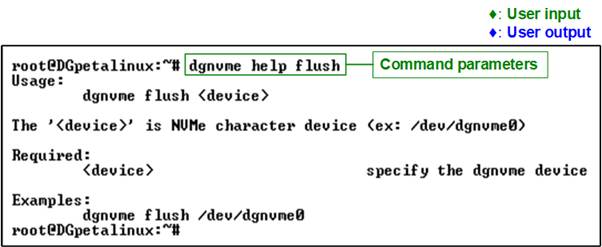
Figure 20 Flush Command Execution (No Options Required)
The Flush command ensures that all data currently stored in the device’s cache memory is properly written to its non-volatile flash memory. This guarantees that no write data lost in the event of an unexpected power-down. The command does not require any additional options; simply specify the device name, as shown in Figure 20.
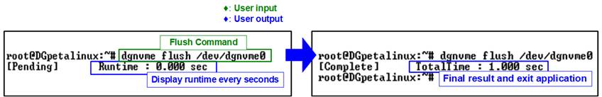
Figure 21 Flush Command Result
During the Flush operation, the console displays the total runtime, which is updated every second. Upon completion, the final execution time is shown, as illustrated in Figure 21.
2.6 Secure Erase Command
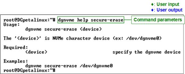
Figure 22 Secure Erase Execution (No Options Required)
The Secure Erase command permanently deletes all user data on the device by initiating a secure erase operation. Depending on the device model, this process may take long time to complete. The command does not require any additional options; simply specify the device name, as shown in Figure 22.
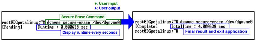
Figure 23 Secure Erase Result
During the Secure Erase operation, the console displays the total runtime, which is updated every second. Upon completion, the final execution time is shown, as illustrated in Figure 23.
2.7 Shutdown Command
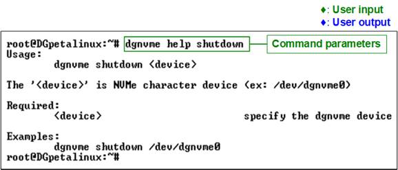
Figure 24 Shutdown Command Execution (No Options Required)
The Shutdown command is used to safely power down the NVMe device. It ensures that all cached data is flushed to non-volatile memory and the device transitions to an inactive state without risk of data corruption. Once shut down, the device will no longer respond to any commands until the system is rebooted and the drive is reinitialized. This command does not require any additional options; simply specify the device name, as shown in Figure 24.
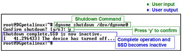
Figure 25 Shutdown Command Result
After the user enters the Shutdown command, the system prompts for confirmation, as shown in Figure 25. To proceed, the user must type “y”. Once confirmed, the Shutdown command is issued to initiate the power-down process.
Upon successful completion, the application displays a message indicating that the device is now inactive. At this stage, the device is removed from the kernel and becomes inaccessible. As a result, no further test operations can be performed until the system is restarted and the NVMe device is reinitialized. This behavior is illustrated in Figure 26, where the device is no longer detected following the completed shutdown operation.
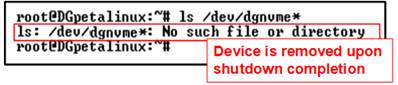
Figure 26 Device Removed After Shutdown Completes
3 Revision History
|
Revision |
Date (D-M-Y) |
Description |
|
1.01 |
2-Jul-25 |
Update driver module name, help write option, and help read option |
|
1.00 |
19-May-25 |
Initial version release |