100G Ethernet Data Logger Using NVMe-IP for Gen5
Reference Design Manual
1.1 Scalable 100G Ethernet Data Logger
1.2 100G Ethernet Data Logger Base System
2.1 Ethernet Front-End and Packet Filtering
2.2 Packet Processing and Encoding
2.3 DDR Buffering and Flow Control
2.4 File System and NVMe Storage
2.4.1 exFAT2-IP for NVMe-IP Gen5
2.5 System Control and Management
3.1 Test Firmware (ethernetdatalogger.c)
3.1.1 Display Packet Filter Setting
3.1.2 Display File System Information
3.2 Function List in Test Firmware
1 Overview
Modern high-speed networks operate at line rates ranging from multi-gigabit to hundreds of gigabits per second. Environments such as cloud data centers, telecom infrastructures, and high-performance computing systems require not only high throughput but also strong observability to ensure system reliability, rapid fault isolation, and effective post-event analysis.
The Ethernet Data Logger is designed to provide high-speed packet capture and long-term traffic backup for deep analysis. In addition to fault diagnosis, it continuously preserves Ethernet traffic as historical data, enabling protocol verification, traffic pattern analysis, and performance evaluation that may not be reproducible in live systems.
Conventional Ethernet data loggers are typically CPU-based, relying on software packet capture and temporary storage in system memory before writing data to disks. This approach consumes significant computing resources and introduces latency and throughput bottlenecks, making sustained full-rate capture at 100 Gbps difficult.
To address these limitations, the FPGA-based 100G Ethernet Data Logger is developed without CPU or operating system involvement to provide deterministic and efficient packet logging with predictable performance.
1.1 Scalable 100G Ethernet Data Logger
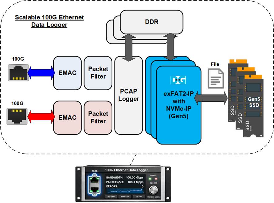
Figure 1 Scalable 100G Ethernet Data Logger
Built on the FPGA, the 100G Ethernet Data Logger provides a flexible platform for various high-speed data logging or monitoring applications. Using the configurable features of FPGA, the number of DDRs, SSDs, and Ethernet channels can be adjusted, matching the specific applications.
As shown in Figure 1, the Scalable 100G Ethernet Data Logger system provides two 100G Ethernet channels and operates transparently as an inline device, forwarding all Ethernet traffic between connected systems while simultaneously capturing packets based on user-defined rules. Only selected packets are packed into PCAPNG format and buffered in DDR before being recorded to NVMe Gen5 SSDs using Design Gateway’s exFAT-IP and NVMe-IP, achieving SSD-level throughput of up to 11.4 GB/s.
1.2 100G Ethernet Data Logger Base System
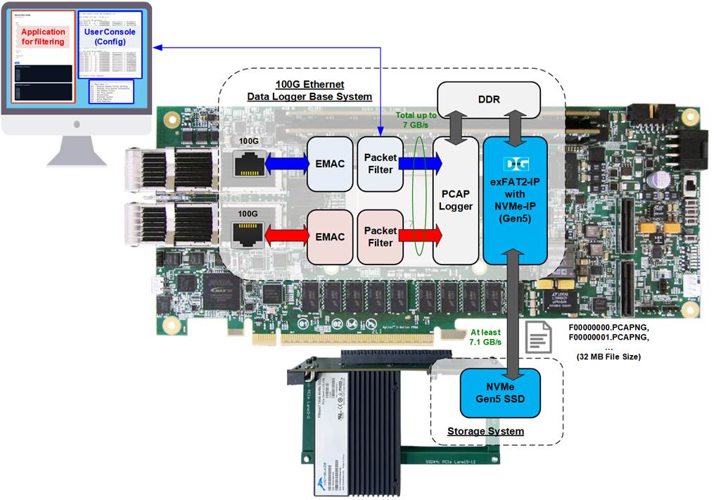
Figure 2 100G Ethernet Data Logger Base System
The base system for the 100G Ethernet Data Logger is implemented using the Agilex 7 FPGA I-Series development kit. To minimize hardware resource usage, the system is configured with a single DDR SO-DIMM and a single NVMe Gen5 SSD. With this configuration, the maximum sustained throughput for Ethernet packet logging is limited to 7 GB/s, as shown in Figure 2.
Captured Ethernet packets are processed by the Packet Filter and temporarily buffered in DDR before being recorded to the NVMe SSD using Design Gateway’s exFAT2-IP. The data is stored in the exFAT file system with fixed file size and predefined file naming rules, allowing direct access from standard host systems.
The key features and constraints of the base system are summarized below:
· Packet Filter supports packet header verification using up to 8 configurable rules.
· Captured packets are stored in PCAPNG format with sequential filenames (F0000000.PCAPNG, F0000001.PCAPNG, …).
· Each PCAPNG file has a fixed size of 32 MB.
· NVMe SSD capacities of up to 512 TB are supported.
· Data logging automatically stops when the SSD reaches full capacity.
· The NVMe Gen5 SSD must support a minimum sustained write throughput of 8.4 GB/s.
Since the Packet Filter requires multiple parameters to configure the 8 verification rules, Design Gateway provides a PC-based sample application to assist users in converting standard Ethernet protocol fields and commonly used network parameters into the required Packet Filter configuration.
System control and monitoring are performed through the NIOS console, which is connected via JTAG. The console allows users to configure Packet Filter parameters, start and stop data logging, and monitor system operation status.
Further details of the hardware and software architecture of the base system are described in the following sections.
2 Hardware
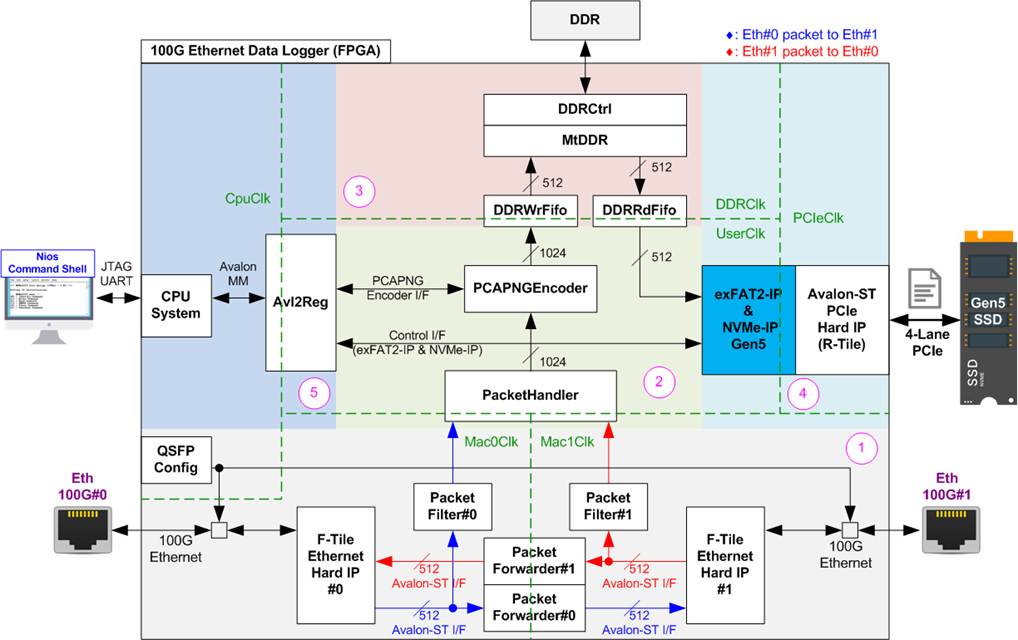
Figure 3 100G Ethernet Data Logger Demo Hardware
The 100G Ethernet Data Logger hardware architecture is organized into five functional blocks, each responsible for a specific stage of packet forwarding, capturing and processing, buffering, storage, and system control.
(1) Ethernet Front-End and Packet Filtering: This block consists of QSFP Config, F-Tile Ethernet Hard IP, Packet Forwarder, and Packet Filter modules. The Ethernet front-end provides connectivity between two external Ethernet devices using two F-Tile Ethernet Hard IPs. Each Ethernet interface connects to a Packet Forwarder, enabling transparent and asynchronous packet forwarding between the two ports to maintain normal system operation. Packet Filter modules monitor traffic on each channel and forward only packets matching user-defined filter rules to the packet processing block for logging.
(2) Packet Processing and Encoding: This block consists of PacketHandler and PCAPNGEncoder modules. The packet processing block receives filtered packets from both Packet Filter instances. The PacketHandler merges the two 512-bit input streams into a single 1024-bit data stream and forwards it to the PCAPNGEncoder. The PCAPNGEncoder converts the incoming packets into the standard PCAPNG file format and outputs the encoded data to the DDR buffering block.
(3) DDR Buffering and Flow Control: This block consists of MtDDR and DDRCtrl modules. The DDR buffering block temporarily stores the PCAPNG-encoded data in external DDR memory. When sufficient data has accumulated, the buffered data is read out and transferred to the storage subsystem.
(4) File System and NVMe Storage: This block consists of exFAT2-IP, NVMe-IP Gen5, and R-Tile PCIe Hard IP modules. This block handles file system management and high-speed data storage. Using exFAT2-IP and NVMe-IP Gen5, the system writes PCAPNG files directly to the NVMe Gen5 SSD through the R-Tile PCIe Hard IP. File system commands and parameters required by exFAT2-IP are controlled by the CPU via the Avl2Reg interface.
(5)
System Control and Management: This block consists of CPU and
Avl2Reg modules. The CPU provides overall system control and configuration.
Through the Avl2Reg module, it manages hardware parameters, controls data
capture operations, and monitors system status. User interaction is supported
via the integrated JTAG UART interface, enabling configuration, start/stop
control, and runtime monitoring.
As shown in Figure 3, the demo hardware utilizes multiple clock domains to interface with hardware modules that require specific base clock frequencies for synchronization with external devices, as summarized below:
· Mac0Clk/Mac1Clk are the operating clocks for the two F-Tile Ethernet Hard IPs that manage the 100 GbE interfaces. Each clock runs at 402.832 MHz, matching the frequency required for 100G Ethernet data transfer.
· DDRClk drives the DDR memory interface and its controller (MtDDR and DDRCtrl) and runs at 333.333 MHz to support high-throughput memory transactions.
· PCIeClk is generated by the PCIe Hard IP to synchronize data streams over the Avalon-ST interface. In this reference design, the interface is configured as a 4-lane PCIe Gen5 operating at 500 MHz.
· CpuClk serves as the clock domain for the CPU and its peripherals, requiring a stable clock independent of other hardware components.
· UserClk is used for the operation of the exFAT2-IP, NVMe-IP Gen5, PacketHandler, and PCAPNGEncoder. According to the NVMe-IP for Gen5 datasheet, the UserClk frequency must be greater than or equal to half of PCIeClk. In this design, UserClk is set to 280 MHz, satisfying this requirement (> 250 MHz).
Further details of each module within the 100G Ethernet Data Logger using NVMe-IP system are described in subsequent sections.
2.1 Ethernet Front-End and Packet Filtering
The Ethernet interface section is responsible for managing high-speed network communication between the two 100G Ethernet ports in the data logger system. It handles Ethernet packet transmission and reception, as well as the transfer of data between external devices and the internal processing path. This section describes the main Ethernet-related modules used in the design and their configuration for stable 100G operation.
2.1.1 F-Tile Ethernet Hard IP
The F-Tile Ethernet Hard IP integrates the MAC, PCS, and PMA layers, providing a high-speed Ethernet interface for external devices over 100GBASE-SR. The IP Core provides a 512-bit MAC Segmented user interface operating at 402.832 MHz.
For detailed information on the F-Tile Ethernet Hard IP, refer to the “F-Tile Ethernet Hard IP User Guide” on the Altera website.
https://www.altera.com/products/ip/a1jui0000049uuumam/agilex-7-f-tile-ethernet-hard-ip
In this reference design, the recommended configuration parameters for the F-Tile Ethernet Hard IP are listed below.
General Options
· PMA type : FGT
· Ethernet mode : 100GE-4
· Client interface : MAC segmented
· FEC mode : IEEE802.3 RS(544,514) (CL134)
· PMA reference frequency : 156.25 MHz
· System PLL frequency : 830.078125 MHz
MAC Options
· Tx maximum frame size : 9014
· Rx maximum frame size : 9014
2.1.2 QSFPConfig
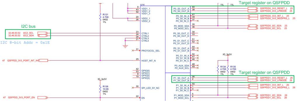
Figure 4 QSFPDD I/O Schematic on Agilex7 I-Series Development Kit
On the Agilex 7 I-Series development kit, the ‘QSFP_RESET_L’ and ‘QSFP_LPMODE’ signals on the QSFP-DD transceiver are configured via an I/O Expander module, which is controlled through a two-line I2C bus protocol. The QSFPConfig module is specifically designed as an I2C master to configure these signals by setting ‘QSFP_RESET_L’ to 1b and ‘QSFP_LPMODE’ to 0b. This configuration ensures proper operation and low-power mode management of the QSFPDD transceiver for high-speed data transfer in 100G Ethernet test environment.
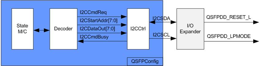
Figure 5 QSFPConfig Block Diagram
The QSFPConfig module includes the I2CCtrl submodule, which functions as the I2C master controller. It is responsible for writing one-byte data (I2CDataOut) to a target register (I2CStartAddr). Within the I2CCtrl logic, the I2C device address and clock divider are preset, operating the I2C clock (SCL) at 400 kHz.
The QSFPConfig module features a state machine that configures two registers of the I/O Expander:
· The Output Enable Register (Address: 08h) for ‘OUT_A’ and ‘OUT_B’
· The Output Value Register (Address: 0Ah) for ‘OUT_A’ and ‘OUT_B’
By default, the ‘QSFP_RESET_L’ and ‘QSFP_LPMODE’ signals, assigned to P0 and P1, are set to disabled (Hi-Z). To initialize the QSFP-DD transceiver, the state machine performs the following sequence.
1) Enable Output: The Output Enable Register of the P0 and P1 ports is set to enable output by assigning I2CStartAddr=08h and I2CDataOut=FFh (enable all outputs).
2) Reset QSFPDD: The Output Value Register of the P0 and P1 ports is written with I2CStartAddr=0Ah and I2CDataOut=00h to assert ‘QSFP_RESET_L’ to 0b.
3) Release QSFPDD Reset: The Output Value Register of the P0 and P1 ports is updated with I2CStartAddr=0Ah and I2CDataOut=0Fh to de-assert ‘QSFP_RESET_L’ to 1b.
Once the register configuration is completed, the QSFPConfig module transitions to an Idle state. This configuration of P0 and P1 runs once after system power-up.
The timing diagram for the I2CCtrl user interface is shown in Figure 6.
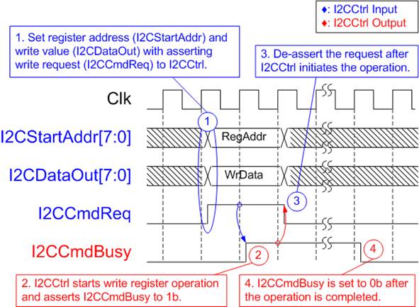
Figure 6 I2CCtrl Timing Diagram
1) I2CCmdReq is asserted to 1b with valid values for I2CStartAddr and I2CDataOut. These inputs must remain unchanged until I2CCtrl asserts I2CCmdBusy to 1b.
2) I2CCmdBusy is set to 1b once I2CCtrl loads the input parameters and begins the write operation.
3) I2CCmdReq is then set to 0b to clear the write request and prepares the parameters for the next operation.
4) When the write operation is complete, I2CCmdBusy is de-asserted to 0b.
2.1.3 PacketForwarder
The PacketForwarder is designed to transfer Ethernet packets between two Ethernet Hard IPs that operate in different clock domains. Although both Ethernet Hard IPs use a 512-bit Avalon-ST interface, their interface characteristics are different and therefore they cannot be connected directly.
To receive an Ethernet packet from the Ethernet Hard IP, the logic must always be ready and cannot insert any pause during data transmission. In contrast, when transmitting an Ethernet packet to the Ethernet Hard IP, the logic must support pausing the data transmission if the Ethernet Hard IP de-asserts the ready signal to request a pause.
Consequently, the PacketForwarder includes an Asynchronous FIFO to store Ethernet packets received from the first endpoint before forwarding them to the other endpoint, as shown in Figure 7.
The maximum Ethernet packet size is 9014 bytes. Therefore, the FIFO size (MacFf) must exceed this value to ensure that an entire Ethernet packet can be stored before it is forwarded to the other endpoint.
To monitor whether a complete packet has been stored in MacFf, the AsyncCounter module is used to track the number of complete packets stored in the FIFO.
The AsyncCounter provides flow-control functionality similar to an Asynchronous FIFO but does not contain any memory for storing data. Instead, it only provides flow-control signals for write and read operations: WrEn, Full, RdEn, and Empty.
The minimum Ethernet packet size is 64 bytes, which corresponds to one entry of MacFf. Therefore, the maximum number of packets that can be stored in MacFf equals its depth (512). To track up to 512 packets, the AsyncCounter uses a 9-bit counter, which supports up to 512 entries (29).
Further details of the PacketForwarder logic are described in the following two subsections: Write FIFO interface (operates in the MacRxClk domain) and Read FIFO interface (operates in the MacRxClk domain).
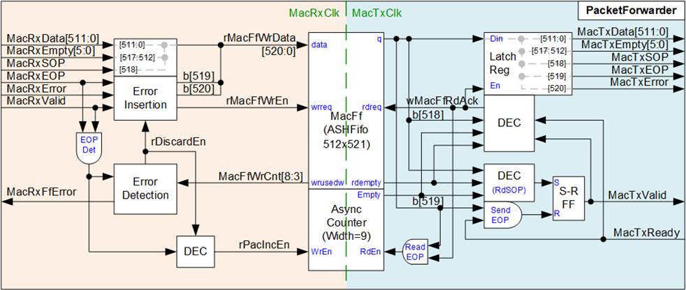
Figure 7 PacketForwarder Logic Diagram
Write FIFO Interface
The Write FIFO Interface operates in the MacRxClk domain and receives Ethernet packets from the first Ethernet Hard IP through a 512-bit Avalon-ST interface. Since the receive interface does not support backpressure, the logic must always be ready to accept incoming data and cannot pause the data transmission.
During normal operation, the received Ethernet packet is written directly to the asynchronous FIFO (MacFf). Each FIFO entry contains 521 bits of information, consisting of 512-bit packet data, 6-bit Empty field (indicating the number of valid bytes in the final data strobe), 1-bit SOP (Start of Packet) flag, 1-bit EOP (End of Packet) flag, and 1-bit Error flag.
When the final data of a packet is written to MacFf (EOP asserted), the write enable signal of the AsyncCounter is also asserted. This operation increments the write pointer of the AsyncCounter, indicating that a complete packet has been stored in the FIFO.
The design assumes that the receive bandwidth from the first Ethernet Hard IP does not exceed the transmit bandwidth of the other Ethernet Hard IP. Therefore, when both the FIFO write logic and read logic operate without overhead, the FIFO should never become full.
To detect abnormal conditions, the FIFO write counter (MacFfWrCnt) is monitored. If the counter reaches a predefined threshold, an error signal is asserted. At the same time, rDiscardEn is asserted to terminate the current packet write operation by forwarding the current packet data to MacFf with the EOP and error flag asserted, indicating that the packet contains an error. Any remaining portion of the packet is discarded.
rDiscardEn is de-asserted once MacFfWrCnt falls below the threshold value, allowing subsequent packets to be stored in MacFf and forwarded to the other Ethernet Hard IP, as illustrated in Figure 8.
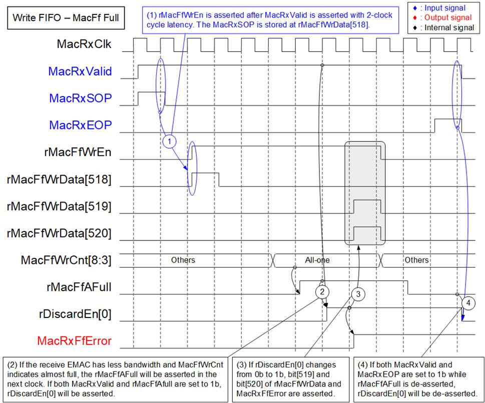
Figure 8 Timing Diagram of
Writing FIFO But FIFO Is Full
1) Normally, all received data from the Ethernet MAC are stored in MacFf by asserting rMacFfWrEn to 1b after MacRxValid is asserted with a 2-clock-cycle latency. MacRxSOP, MacRxEOP, and MacRxError are loaded into bit[518], bit[519], and bit[520] of rMacFfWrData, respectively.
2) If the transmit Ethernet MAC bandwidth exceeds the receive Ethernet MAC bandwidth, MacFf may eventually reach its capacity. When the upper bits of MacFfWrCnt become all ones, the rMacFfAFull is asserted to 1b, indicating the FIFO is almost full.
When both MacRxValid and rMacFfAFull are asserted, rDiscardEn[0] is set to 1b, initiating the packet discard mechanism.
3) When rDiscardEn[0] changes from 0b to 1b, the current data word from the Ethernet MAC is stored to MacFf with both the EOP flag and error flag asserted by setting bit[519] and bit[520] of rMacFfWrData to 1b. This indicates that the packet contains an error.
4) After MacFf recovers its capacity and rMacFfAFull is de-asserted, rDiscardEn[0] is de-asserted to 0b once the last data of the current packet is received (MacRxValid=1b and MacRxEOP=1b).
Additionally, rDiscardEn[0] may also be cleared if rMacFfAFull is de-asserted when no packet transfer is in progress.
However, MacRxFfError is an error signal that can only be cleared by a reset.
Read FIFO Interface
The Read FIFO Interface operates in the MacTxClk domain and forwards Ethernet packets stored in MacFf to the Ethernet MAC through the MacTx interface.
To support the ready/valid handshake mechanism of the transmit interface, a latch register is used to hold all output signals, including the 512-bit data, 6-bit empty flag, SOP flag, EOP flag, and Error flag. These signals remain stable until MacTxReady is asserted, indicating that the Ethernet MAC has accepted the transmitted data word. Once the data is accepted, the next data word is loaded from MacFf to continue the packet transfer.
A new packet transfer is initiated only when the following conditions are satisfied:
· At least one complete Ethernet packet is stored in MacFf, indicated by both the MacFf empty flag and the AsyncCounter empty flag being de-asserted (0b).
· No remaining data from a previous packet transfer, which is determined by monitoring the MacTxValid and MacTxReady signals.
When both conditions are satisfied, wMacFfRdAck is asserted to read the first data word of the packet from MacFf.
The entire packet is then transferred continuously to the Ethernet MAC by keeping MacTxValid asserted (1b) from the first data word until the final data word of the packet.
When the last data word of the packet is read from MacFf (EOP asserted), the read enable signal of the AsyncCounter is also asserted. This operation decrements the packet counter, indicating that one complete packet has been removed from the FIFO.
2.1.4 PacketFilter
The PacketFilter module is designed to capture only the Ethernet packets that match the specified filtering rules and forward them to the storage system. The system supports up to eight filtering rules, and an incoming packet is captured if it matches any configured rule.
Each rule is configured using a 38-byte pattern together with a 38-bit byte-enable mask. The first 38 bytes of each Ethernet packet, referred to as the packet header, are compared against the configured patterns of all enabled rules (up to eight rules). Therefore, this module is implemented as a set of comparators with configurable byte masks, as illustrated in Figure 9.
· Rx I/F is a 512-bit Avalon-ST interface tapped from the input interface of the PacketForwarder module.
· Tx I/F is a 512-bit Avalon-ST interface that forwards packets to the input interface of the PacketHandler module.
· FilterHdData is a set of 38-byte patterns configured by the user to match the incoming packet header. Eight data sets are provided to support eight filtering rules.
· FilterHdMask is a 38-bit byte mask used to enable comparison between the incoming packet header and the configured pattern (FilterHdData). Each bit corresponds to one byte of FilterHdData. Eight mask sets are provided to support eight rules.
· FilterHdRuleEn is a control signal used to enable each individual filtering rule.
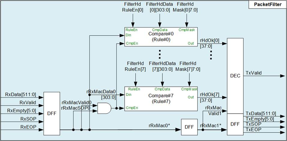
Figure 9 PacketFilter Logic Diagram
Packet capture is controlled by the TxValid signal. This signal is asserted only when the received packet matches any filtering rule. The remaining Avalon-ST signals—including the 512-bit data, 6-bit empty field, SOP flag, and EOP flag—are forwarded from the receive interface to the transmit interface through a three-stage pipeline of D Flip-flops.
2.2 Packet Processing and Encoding
The Packet Processing and Encoding stage prepares filtered Ethernet packets for storage by organizing packet data and converting it into a standardized capture file format. This stage receives packet streams from two PacketFilter modules associated with the Ethernet interfaces and processes them into a unified packet stream suitable for file generation.
This section consists of two main modules: PacketHandler and PCAPNGEncoder. The PacketHandler module collects packet data from multiple Ethernet ports, buffers the packets, and arranges them into a single ordered packet stream. The PCAPNGEncoder module formats the processed packet stream into the PCAP Next Generation (PCAPNG) file format. It generates the required block structures, encapsulates packet payloads, attaches timestamps, and inserts the metadata required by the PCAPNG specification.
Further details of each module are described in the following subsections.
2.2.1 PacketHandler
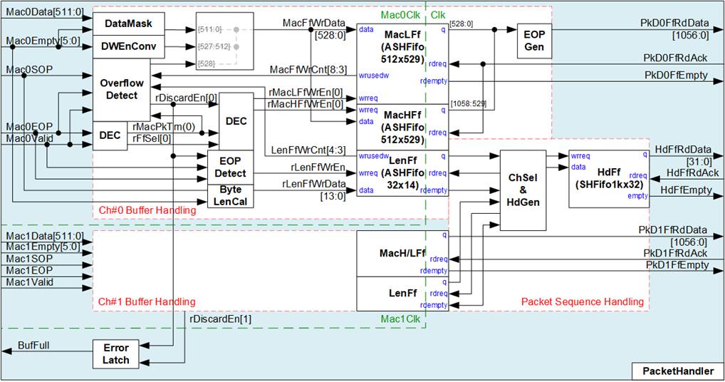
Figure 10 Packet Handler Logic Diagram
The PacketHandler module receives Ethernet packets from two PacketFilter modules, encodes them, and stores them in internal FIFOs before forwarding them to the PCAPNGEncoder.
The input packet streams are provided as 512-bit Avalon-ST interfaces operating in the Mac0Clk and Mac1Clk domains. The output interface toward the PCAPNGEncoder consists of three FIFO interfaces in the Clk domain: two FIFOs for packet payload transfer (one per Ethernet channel) and one FIFO for packet header and packet ordering information. All FIFO interfaces are show-ahead type, meaning data is valid when the FIFO is not empty.
To support packet transfers from two Ethernet channels without packet loss, the payload data width is increased from 512 bits to 1024 bits. Both data width conversion and clock domain crossing are implemented using asymmetric asynchronous FIFOs (MacLFf and MacHFf). The payload output signal (PkDRdData) contains 1024-bit data, 32-bit double word enable, and 1-bit EOP flag.
Additionally, packet header information is generated once per packet and stored in HdFf. The 32-bit header includes 14-bit packet byte size, 5-bit packet double-word size, 12-bit EPB (Enhanced Packet Block) size, and 1-bit Ethernet channel ID (0b: Mac#0, 1b: Mac#1).
Based on the operation flow, the PacketHandler logic is divided into two functional groups: Write Interface of MacFf (Buffer Handling) and Write Interface of HdFf (Packet Sequence Handling), as shown in Figure 10.
Write Interface of MacFf (Buffer Handling)
To increase the data width from 512 bits to 1024 bits, each input channel uses two asynchronous Show-Ahead FIFOs (MacLFf and MacHFf) to store incoming data. Each FIFO stores 529-bit data, consisting of 512-bit payload data, 16-bit double-word enable field, and 1-bit EOP (end-of-packet) flag.
The two FIFOs are written alternately on each write cycle, forming a 1024-bit output data word. The first data word is written to MacLFf by asserting rMacLFfWrEn[0], while the next data word is written to MacHFf by asserting rMacHFfWrEn[0]. The active FIFO is toggled between MacLFf and MacHFf every write cycle, controlled by rFfSel[0].
The 6-bit empty status is decoded in each write cycle to determine the number of valid data units (in double-word unit), which is used to generate the double-word enable field at bits[527:512] of MacFfWrData. Typically, all 512-bit input data are valid except for the last cycle of a packet. According to the PCAPNGEncoder requirement, if the final packet data does not align to 1024 bits, the unused portion must be padded with zeros. Therefore, the empty status is also used as a mask to generate zero values for unused bytes in the last data word.
During each write cycle, the number of valid bytes is accumulated by ByteLenCal, which determines the packet byte size. When the last data word of a packet is received, EOPDetect generates a pulse to write the accumulated byte length to LenFf.
By inserting zero data to align the payload to 1024 bits, the number of entries written to MacLFf and MacHFf becomes equal. As a result, only the write counter of MacLFf (MacFfWrCnt) is monitored, while the write counter of MacHFf is not required. In addition, the write counter of LenFf (LenFfWrCnt) is monitored to track buffer usage.
When either MacFfWrCnt or LenFfWrCnt reaches a predefined threshold indicating a potential overflow condition, rDiscardEn[0] is asserted. In this state, the remaining payload of the current packet is discarded, and the last stored data word is marked with the EOP flag to terminate the packet.
After this, all subsequent packets are discarded until both FIFOs indicate sufficient available space. Once the buffers become available again, packet storage resumes from the start of a new packet, ensuring that only complete packets are forwarded. The timing diagram illustrating the FIFO full condition is shown below.
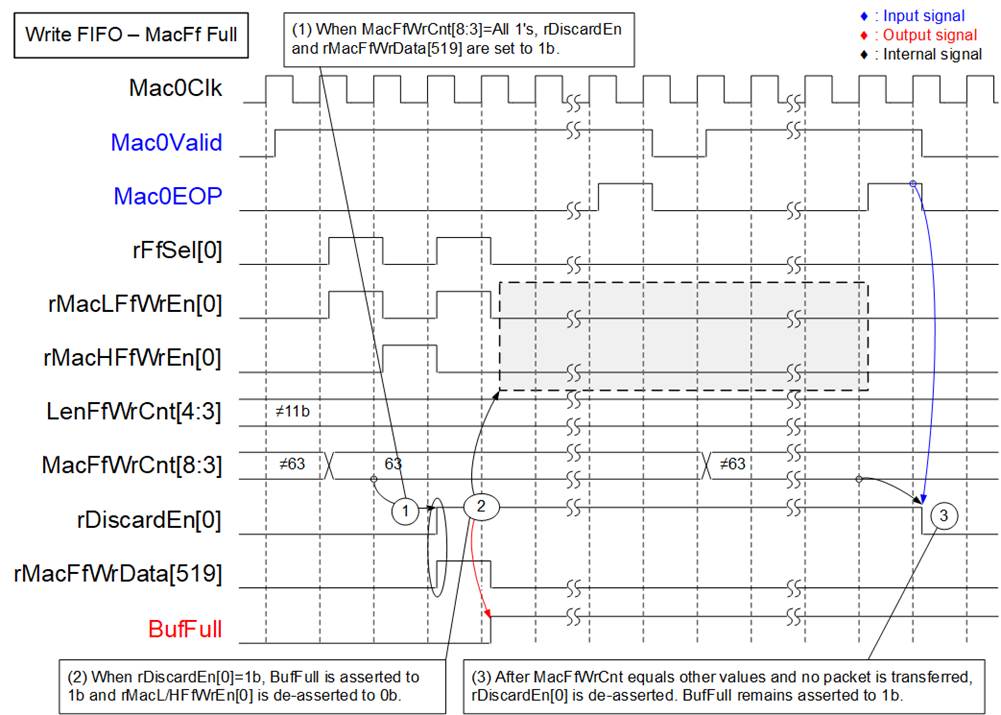
Figure 11 FIFO Overflow Timing
Diagram
1) When MacLFf does not have sufficient available space (MacFfWrCnt[8:3]=63) and new data is received (Mac0Valid=1b), the current packet write operation is terminated by asserting rDiscardEn[0] to 1b. At the same time, the EOP flag (rMacFfWrData[519]) is forced to 1b, marking the current data word as the last data of the packet.
2) The buffer full status (BufFull) is asserted, indicating that a buffer overflow condition has occurred and packet loss has been detected. While rDiscardEn[0] remains asserted, no additional packet data is written to MacLFf or MacHFf (rMacLFfWrEn[0]=0b and rMacHFfWrEn[0]=0b).
3) Once MacLFf has sufficient available space (MacFfWrCnt[8:3]≠63), the logic waits until the current packet transfer is completed (Mac0Valid = 1b and Mac0EOP = 1b) or no packet transfer is in progress.
When these conditions are satisfied, rDiscardEn[0] is de-asserted, allowing packet write operation to resume. The next packet is then stored by asserting rMacLFfWrEn[0] and rMacHFfWrEn[0].
Write Interface of HdFf (Packet Sequence Handling)
This subblock is responsible for ordering packets from two Ethernet channels into a single output stream for the PCAPNGEncoder, while also generating the corresponding packet headers. The operation of the ChSel & HdGen block is as follows:
1) Monitor the empty status of LenFf from both channels and determine the active channel. The selected channel is switched after the last data word of each packet is transferred, ensuring balanced processing between the two Ethernet channels.
2) The 14-bit packet byte size is used to derive two additional parameters: Packet size in double-word units (bits[19:14]) and EPB (Enhanced Packet Block) length (bits[31:20]).
3) When a packet entry is read from the active LenFf, the following fields are combined to form a 39-bit header: 14-bit packet byte size, 12-bit packet size in double-word units, 12-bit EPB length, and 1-bit Channel ID (indicating the source Ethernet channel). This header is written to HdFf.
Compared to the per-channel packet buffer depth (512), HdFf has a depth of 1024, which is sufficient to store headers from both channels.
The logic can retrieve and process data from LenFf every clock cycle, which is sufficient to support packet transfers from two 100G Ethernet channels.
2.2.2 PCAPNGEncoder
PCAPNG is a standardized file format for storing captured network packets along with metadata such as timestamps and interface information. The format supports multiple block types, optional fields, and extensibility through custom blocks. All block structures and field definitions used by this design follow the PCAPNG Capture File Format Specification: https://github.com/IETF-OPSAWG-WG/pcapng
The PCAPNGEncoder module encodes incoming Ethernet packets into the PCAPNG file format, as illustrated in Figure 12.
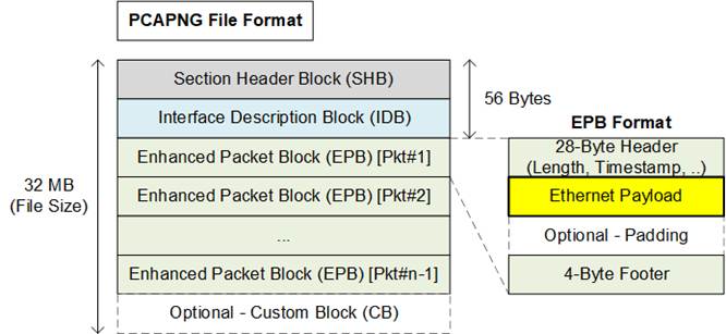
Figure 12 PCAPNG File Format
In this demo, PCAPNG file size is configured to 32 MB. At the beginning of each file, the following two block types are written within the first 56 bytes:
· Session Header Block (SHB): Marks the start of a capture session and defines the file format
· Interface Description Block (IDB): Describes the capture interface used for packets in the file
After that, each Ethernet packet received from the PacketHandler is encapsulated into an Enhanced Packet Block (EPB) by appending:
· 28-byte header (including packet length, timestamp, etc.)
· The packet payload
· Optional padding bytes (if the payload is not aligned to 4 bytes)
· 4-byte footer
To ensure the total file size reaches 32 MB, a Custom Block (CB) is appended as padding if the final EPB does not align with the configured file size.
To generate the PCAPNG format, additional header, padding, and footer data must be appended to each packet, increasing the required output bandwidth of the PCAPNGEncoder. In the worst-case scenario, when 61-byte Ethernet packets are received continuously, each EPB consists of 28-byte header, 61-byte payload, 3-byte padding, and 4-byte footer. This results in a total of 96 bytes per packet, requiring approximately 157.38% of the original Ethernet bandwidth to record packets without loss.
Based on a 1024-bit data interface, achieving full throughput for 2 × 100 GbE requires approximately:
157.38% × 195.3125 MHz ≈ 308 MHz
In this system, the bottleneck is the DDR bandwidth, as only a single DDR module is used. Therefore, the PCAPNGEncoder is configured to operate at 280 MHz. The operating frequency can be adjusted based on system requirements.
The PCAPNGEncoder in this reference design is provided as an encrypted IP, allowing usage without modification. For customization or additional features, please contact our sales team.
The interface and internal details of the PCAPNGEncoder are illustrated in Figure 13.
Hardware Design
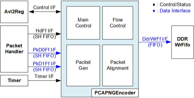
Figure 13 PCAPNGEncoder Block Diagram
The logic inside PCAPNGEncoder is divided into four functional groups:
· Main Control:
This module controls the sequence for generating the PCAPNG file, as described below:
1) Wait for the user to initiate the recording process, monitored via the Control I/F of Avl2Reg. Proceed to the next step when a request is detected.
2) Ensure that no stop request is issued by the user and the SSD has not reached full capacity.
3) Enable PCAPNG file header generation, including SHB and IDB.
4) Wait until HdFf contains valid data to initiate EPB generation. During this period, if the user stops recording or the SSD reaches capacity, the file is finalized.
CB generation is performed during file finalization and the current file size is not aligned to 32 MB.
5) Retrieve packet information from HdFf I/F, including packet length, EPB header information, and Ethernet channel ID.
- If the remaining file space is insufficient for the next EPB, finalize the file (apply CB padding if the file size is not aligned to 32 MB). Return to step (2).
- Otherwise, proceed to the next step.
6) Retrieve the Ethernet packet from PkD0Ff I/F or PkD1Ff I/F, based on the channel ID.
7) Determine whether EPB padding is required. After processing, return to step (4) for the next packet.
· Flow Control:
During packet generation, the write counter of DdrWrFf I/F is continuously monitored to ensure sufficient FIFO space for incoming data. If the available space reaches a critical level, packet retrieval from PkD0Ff I/F or PkD1Ff I/F is paused until sufficient space becomes available.
As a result, the throughput of the PCAPNGEncoder is directly limited by the availability of DDRWrFf. Maximum throughput is achieved when the FIFO remains ready to accept data continuously.
· Packet Gen:
This block generates PCAPNG blocks, including SHB, IDB, EPB, and CB, to form a complete PCAPNG file. For EPB generation, packet length is retrieved from HdFf I/F and packet payload is retrieved from PkD0Ff I/F or PkD1Ff I/F.
· Packet Alignment:
The data interfaces of PkD0Ff I/F, PkD1Ff I/F, and DDRWrFf I/F are 1024 bits wide, while EPB structures require 32-bit alignment. Therefore, alignment logic is implemented to pack multiple EPBs efficiently into the 1024-bit data path, ensuring proper formatting while maximizing bandwidth utilization.
Description of all I/O signals of PCAPNGEncoder are provided in Table 1.
Table 1 I/O Signals of PCAPNGEncoder module
|
Signal name |
Dir |
Description |
|
Control Interface |
||
|
RstB |
In |
Synchronous reset. Active low. |
|
Clk |
In |
Clock signal for the PCAPNGEncoder module. |
|
RecordLen[26:0] |
In |
Number of files to be recorded. This value is valid when RecordStart = 1b. |
|
RecordStart |
In |
Start control signal. Asserted to 1b to initiate recording. Once RecordBusy is asserted to 1b, de-assert this signal to 0b. |
|
RecordStop |
In |
Stop control signal. Asserted to 1b as a pulse to immediately stop recording. |
|
RecordBusy |
Out |
Busy status. Asserted to 1b when the module is processing; de-asserted to 0b when ready to accept RecordStart. |
|
RecordStopDone |
Out |
Stop completion status. Asserted to 1b after the module stops due to RecordStop, and de-asserted to 0b when a new recording is started (RecordStart = 1b). This signal is used by other modules to clear incomplete data and status resulting from an immediate stop condition. |
|
Timer Interface |
||
|
TimeStampInitDone |
In |
Indicates completion of timer initialization. Asserted to 1b as a pulse. |
|
TimeStampVal[63:0] |
In |
Timestamp value from the Timer module. This signal is synchronous to Clk. |
|
Header FIFO Interface |
||
|
HdFfRdData[31:0] |
In |
Header FIFO read data used for EPB generation. Valid when HdFfEmpty = 0b. [13:0] – Packet length in bytes. [18:14] – Packet length in DWORD units (rounded up if not aligned). [30:19] – EPB length in DWORD units, including header and footer. [31] – Packet channel ID (0b = PkD0, 1b = PkD1). |
|
HdFfRdAck |
Out |
Read acknowledge signal for HdFf. Asserted to 1b to read and remove the current data from the FIFO. |
|
HdFfEmpty |
In |
Header FIFO empty flag. Asserted to 1b when no data is available; 0b indicates data is available. |
|
Packet Data FIFO Interface |
||
|
PkD0FfRdData[1056:0] |
In |
Packet data FIFO read bus for channel #0. Valid when PkD0FfEmpty = 0b. [1023:0] – Packet data [1055:1024] – DWORD enable mask (1b indicates valid 32-bit data). [1056] – End-of-packet (EOP), active high |
|
PkD0FfRdAck |
Out |
Read acknowledge signal for PkD0Ff. Asserted to 1b to read and remove the current data from the FIFO. |
|
PkD0FfEmpty |
In |
FIFO empty flag for PkD0Ff. Asserted to 1b when no data is available; 0b indicates data is available. |
|
PkD1FfRdData[1056:0] |
In |
Packet data FIFO read bus for channel #1. Valid when PkD1FfEmpty = 0b. [1023:0] – Packet data [1055:1024] – DWORD enable mask (1b indicates valid 32-bit data). [1056] – End-of-packet (EOP), active high |
|
PkD1FfRdAck |
Out |
Read acknowledge signal for PkD1Ff. Asserted to 1b to read and remove the current data from the FIFO. |
|
PkD1FfEmpty |
In |
FIFO empty flag for PkD1Ff. Asserted to 1b when no data is available; 0b indicates data is available. |
|
DDR Write FIFO Interface |
||
|
DdrWrFfWrCnt[15:0] |
In |
Write count of DDRWrFifo. The module stops writing when this value is greater than or equal to 65,520 (bit[15:4] = FFFh). |
|
DdrWrFfWrEn |
Out |
Write enable signal for DDRWrFifo. Asserted to 1b to indicate that valid data is present on DdrWrFfWrData. |
|
DdrWrFfWrData[1023:0] |
Out |
Write data bus to DDRWrFifo. |
Timing Diagram
The operation is controlled by the Avl2Reg module. Recording is initiated by asserting RecordStart signal and terminated by asserting RecordStop signal, as illustrated in Figure 14.

Figure 14 Control I/F of PCAPNGEncoder
1) Before starting a new operation, ensure that RecordBusy is de-asserted to 0b. The user then asserts RecordStart to 1b to initiate the recording process. During this cycle, RecordLength—configured to define the maximum number of files (e.g., based on SSD capacity)—is loaded into the module. If RecordStop is not asserted and the accumulated number of files reaches RecordLength, the module automatically terminates the recording operation.
2) Once the recording process begins, RecordBusy is asserted to 1b, indicating that recording is in progress. During this period, incoming packets are transferred and encoded into the PCAPNG file format.
3) To request termination, the user asserts RecordStop to 1b. The module then completes the ongoing operation by finalizing the current PCAPNG file, including padding and Custom Block (CB), if required. After the file is fully generated, RecordBusy is de-asserted to 0b, and RecordStopDone is asserted to 1b, indicating that the stop request has been completed.
4) RecordStopDone is de-asserted to 0b when a new recording process is initiated by asserting RecordStart to 1b.
The interfaces used to retrieve the packet header and payload from the Packet Handler are implemented as Show-Ahead FIFOs. In this scheme, valid data is presented on the output when the Empty signal is de-asserted to 0b. The details of these interfaces (HdFf I/F, PkD0Ff I/F, and PkD1Ff I/F) are illustrated in Figure 15.
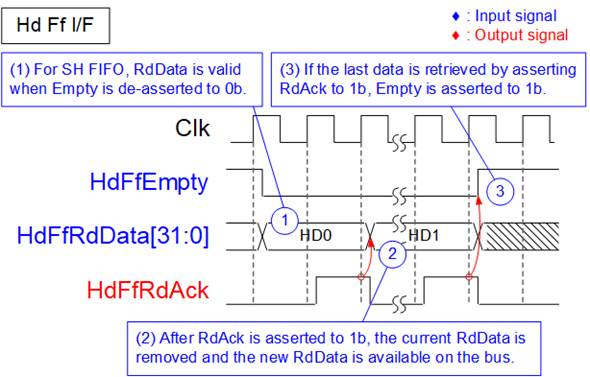
Figure 15 Show-Ahead FIFO I/F of PCAPNGEncoder
1) When Empty is de-asserted to 0b, indicating that data is available in the FIFO, the corresponding data is valid on the RdData bus, matching the show-ahead FIFO behavior.
2) After the current data is consumed, RdAck is asserted to 1b to retrieve and remove the current entry from the FIFO. The next data word becomes valid on the RdData bus in the following clock cycle.
3) When the last data word is retrieved by asserting RdAck, the Empty signal is asserted to 1b, indicating that no data remains in the FIFO.
2.3 DDR Buffering and Flow Control
The MtDDR module serves as the interface layer between the packet processing and file system logic, and the DDR memory subsystem. It provides high-throughput data buffering by coordinating read and write transactions between internal FIFOs and the DDR controller through an Avalon-MM interface.
The MtDDR block consists of two primary submodules:
· MtWrDdr, which handles write transactions from DDRWrFifo to DDR memory
· MtRdDdr, which handles read transactions from DDR memory to DDRRdFifo
To manage flow control between write and read operations, a Data Size Calculator module is included. This module generates two counters:
· WrBufCnt: indicates the amount of data currently stored in DDR, used to determine the remaining buffer capacity
· RdBufCnt: indicates the amount of valid data available in DDR for read operations
These counters are calculated using the write pointer from MtWrDdr and the read pointer from MtRdDdr. The computed values are fed back to both submodules to prevent buffer overflow and underflow conditions.
During operation, MtWrDdr and MtRdDdr perform write and read transactions concurrently, enabling sustained high-bandwidth access to DDR memory.
The external data interface of both MtWrDdr and MtRdDdr is 512-bit wide. The interface to the DDR controller uses the Avalon-MM protocol, while the interfaces to other modules use FIFO-based interfaces, as shown in Figure 16.
Encoded packet data is first written to DDRWrFifo through a 1024-bit FIFO interface, and then stored in DDR memory. Data read from DDR is transferred through a 512-bit FIFO interface to downstream modules, such as exFAT2-IP and NVMe-IP.
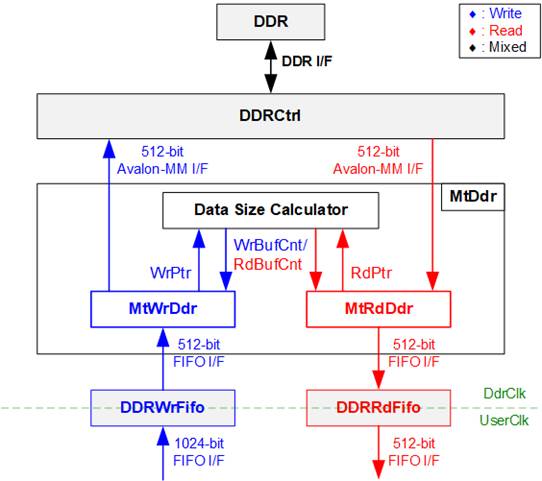
Figure 16 MtDDR Hardware
2.3.1 MtWrDdr
The MtWrDdr module manages write transactions from DDRWrFifo to DDR memory through the DDR controller using an Avalon-MM interface. Its primary responsibility is to sustain high-throughput DDR writes while ensuring proper system readiness and safe buffer conditions.
Before initiating write operations, MtWrDdr monitors DDR initialization status (DDRInitDone), FIFO data availability (TxFfRdCnt), and available DDR buffer space (WrBufCnt). Write transactions are issued only when predefined safety thresholds are satisfied, preventing DDR buffer overflow or FIFO underflow.
To maximize DDR write efficiency, each burst transfer size is fixed at 64 beats of 512-bit data (4 KB per burst).
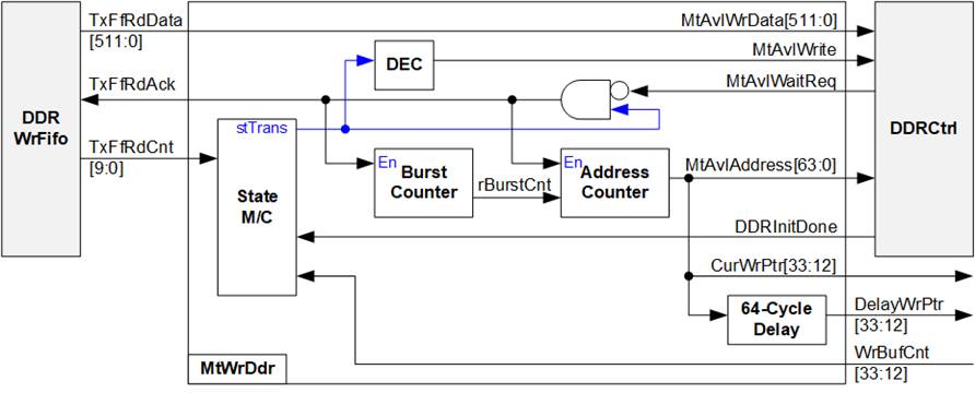
Figure 17 MtWrDdr Hardware
To perform write operations through the Avalon-MM interface, the write address (MtAvlAddress) and the first data (MtAvlWrData) are issued in the same clock cycle, initiating both the write request and data transfer.
The write operation is controlled by a state machine with the following sequence:
1) stInit: Waits for DDR calibration to complete. The state remains in stInit until DDRInitDone=1b, after which it transitions to stChkBufRdy.
2) stChkBufRdy: Checks whether sufficient resources are available to start a write transfer. The state transitions to stTrans only when DDRWrFifo contains at least 4 KB of data and DDR has more than 8 KB of available space. Otherwise, the state remains in stChkBufRdy.
3) stTrans: Performs a 4 KB burst transfer from DDRWrFifo to DDR memory. A burst counter (rBurstCnt) tracks the number of transferred beats and completes a 64-beat burst per transaction. After each burst:
· If DDRWrFifo contains at least 8 KB of data and DDR has more than 16 KB of free space, the next burst starts immediately (continuous transfer).
· Otherwise, the state transitions to stWtDelay.
4) stWtDelay: Introduces a short delay to allow internal counters (e.g., TxFfRdCnt) to update due to pipeline latency.
If sufficient data and DDR space become available, the state transitions back to stTrans. Otherwise, after a fixed delay of four clock cycles, the state returns to stChkBufRdy.
Additionally, MtWrDdr provides a delayed write pointer (DelayWrPtr) with a latency of 64 clock cycles, which is used by the Data Size Calculator to generate the read counter (RdBufCnt). This delay ensures that write transactions are fully completed before corresponding read operations are initiated by MtRdDdr.
2.3.2 MtRdDdr
The MtRdDdr module manages read transactions from DDR memory and forwards the retrieved data into DDRRdFifo. Its primary function is to issue read requests only when sufficient space is available in the DDRRdFifo and valid data is available in the DDR buffer.
For Avalon-MM read transactions, the command request phase and data return phase operate independently. A read request is issued by asserting MtAvlRead along with the address (MtAvlAddress), and the request acceptance is monitored through MtAvlWaitReq. Once the request is accepted, additional read requests can be issued without waiting for the corresponding read data (MtAvlRdData) to return.
Due to this pipelined behavior, the logic must account for outstanding read requests. The remaining FIFO space (rRxFfRemSize) is calculated by subtracting the amount of unreceived data (rUnRcvSize) from the total available FIFO space. This ensures that new read requests are generated only when sufficient space is guaranteed, preventing FIFO overflow.

Figure 18 MtRdDdr Hardware
The read request generation is controlled by a state machine with the following sequence:
1) stChkBufRdy: This is the monitoring state of MtRdDdr. The controller checks at least 8 KB of available space in DDRRdFifo (via RxFfWrCnt) and at least 4 KB of valid data in DDR (via RdBufCnt). When both conditions are satisfied, the state transitions to stRdReq to initiate a DDR read request. Otherwise, it remains in this state.
2) stRdReq: In this state, a DDR read request is issued by asserting MtAvlRead along with the calculated address (MtAvlAddress). The request remains asserted until it is accepted by the DDR controller (MtAvlWaitReq=0b). Once accepted, the state transitions to stDelay.
3) stDelay: This state introduces a short delay of four clock cycles to allow RdBufCnt to update and stabilize before issuing the next request. After the delay, the state transitions back to stChkBufRdy for continued monitoring.
2.4 File System and NVMe Storage
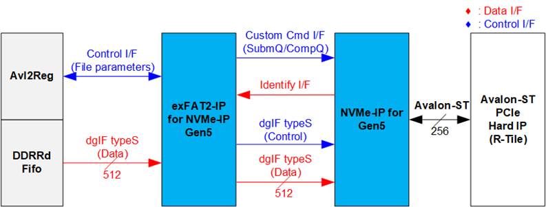
Figure 19 File System and Storage Hardware
The file system and storage hardware in this reference design consist of three main submodules: exFAT2-IP, NVMe-IP, and the Avalon-ST PCIe Hard IP (R-Tile).
The exFAT2-IP provides two types of user interfaces: Control interface for configuring file system parameters and Data interface for transferring file data.
In this design, the Control interface connects to Avl2Reg, allowing the CPU firmware to configure file system parameters and monitor operation status. The Data interface connects to DDRRdFifo, which supplies file data from the DDR buffer during file recording. The exFAT2-IP operates in write-only mode in this reference design; therefore, the read-back interface for file retrieval is not utilized.
The exFAT2-IP directly interfaces with the NVMe-IP to transfer both file system header and file data. The Identify data obtained through the Identify I/F is decoded to verify support for the Secure Format command, enabling the user to select between standard and secure format modes.
The NVMe-IP connects to the Avalon-ST PCIe Hard IP through a 256-bit Avalon-ST interface. Further details of each submodule are provided in the following sections.
2.4.1 exFAT2-IP for NVMe-IP Gen5
The exFAT2-IP is an extension of the NVMe-IP developed by Design Gateway. It enables file-level access to NVMe SSDs using the exFAT file system, while maintaining performance comparable to raw data transfers. When operating at PCIe Gen5 speed, the exFAT2-IP uses a 512-bit data interface.
For more information, refer to the datasheet:
https://dgway.com/products/IP/NVMe-IP/exFAT2-NVMe-IP-g5-datasheet-altera/
2.4.2 NVMe-IP for Gen5
The NVMe-IP for Gen5 implements the NVMe protocol, enabling direct access to the NVMe SSD without using a PCIe switch. It directly connects to the PCIe Hard IP for seamless operation.
For additional details, refer to its datasheet document:
https://dgway.com/products/IP/NVMe-IP/dg_nvme_datasheet_g5_intel/
2.4.3 R-Tile PCIe Hard IP
The R-Tile PCIe Hard IP is an FPGA hard block that implements the Physical Layer, Data Link Layer, and Transaction Layer of the PCIe protocol.
For more information, refer to the Altera documentation:
https://docs.altera.com/r/docs/683501/current
2.5 System Control and Management
To support CPU read and write operations, the hardware logic must comply with the Avalon-MM bus standard. As shown in Figure 20, Avl2Reg is designed to connect the CPU system via the Avalon-MM interface, in compliance with the standard.
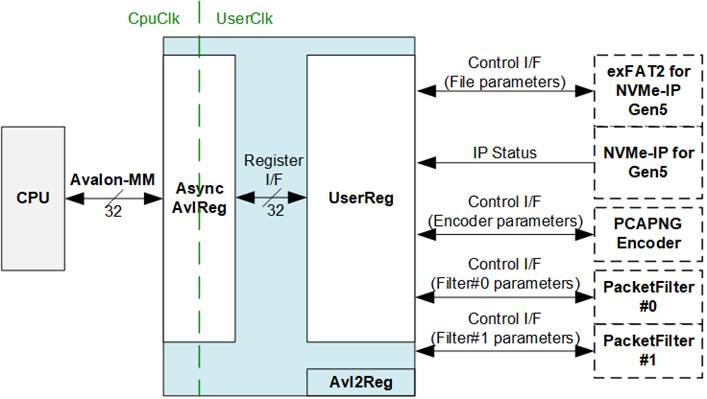
Figure 20 CPU and Peripherals Hardware
Avl2Reg consists of AsyncAvlReg and UserReg. AsyncAvlReg converts Avalon-MM signals into a simplified Register interface with a 32-bit data bus, matching the Avalon-MM data bus width. It also includes asynchronous logic to manage clock domain crossing between the CpuClk and UserClk domains.
UserReg contains the Register file that stores parameters and status signals for various modules in the test system, including exFAT2-IP, NVMe-IP, PCAPNGEncoder, and PacketFilters. Further details about AsyncAvlReg and UserReg are provided below.
2.5.1 AsyncAvlReg
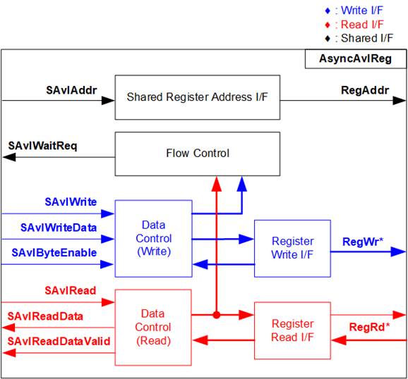
Figure 21 AsyncAvlReg Interface
https://docs.altera.com/r/docs/683091/current
According to the Avalon-MM specification, only one command (write or read) can be executed at a time. AsyncAvlReg’s logic is organized into three groups: Write control logic, Read control logic, and Flow control logic. The flow control logic asserts SAvlWaitReq to hold off subsequent requests from the Avalon-MM interface until the current request completes. Write control and Write data signals of the Avalon-MM bus are latched and transferred to the Write register interface through clock domain crossing registers. Similarly, Read control signals are latched and transferred to the Read register interface. Afterward, the data returned from Register Read I/F is transferred back to Avalon-MM bus using clock domain crossing registers. The Address I/F of Avalon-MM is also latched and transferred to the Address register interface.
The Register interface is compatible with single-port RAM interface for write transactions. However, the read transaction has a slight modification from the RAM interface by adding RdReq and RdValid signals to manage read latency. Since the address of the Register interface is shared for write and read transactions, it cannot handle simultaneous write and read operations. The timing diagram of the Register interface is shown in Figure 22.
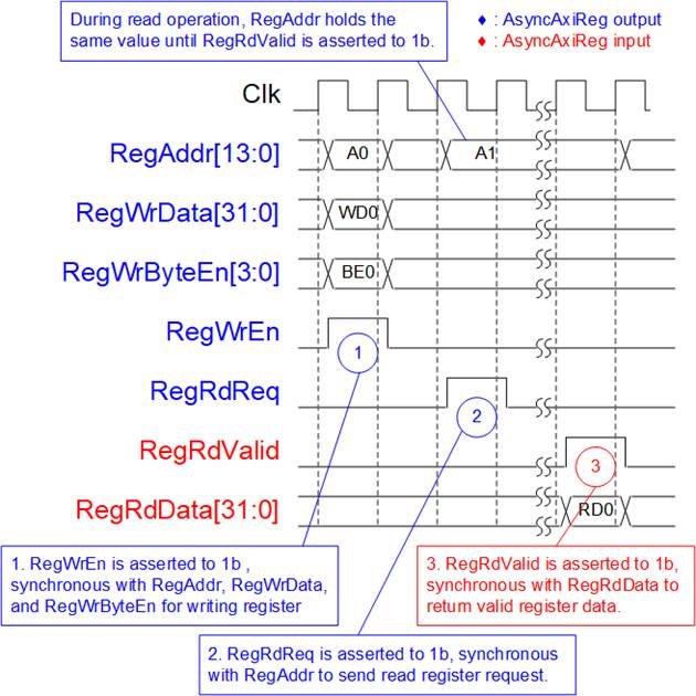
Figure 22 Register Interface Timing Diagram
1) Timing diagram for a write transaction is similar to that of a single-port RAM. The RegWrEn signal is set to 1b, along with a valid RegAddr (the Register address in 32-bit units), RegWrData (write data for the register), and RegWrByteEn (write byte enable). The byte enable is four bits wide, where each bit indicates the validity of a specific byte within RegWrData. For example, if RegWrByteEn[0], [1], [2], and [3] are set to 1b, then RegWrData[7:0], [15:8], [23:16], and [31:24] are valid, respectively.
2) To read from a register, AsyncAvlReg sets the RegRdReq signal to 1b, along with a valid value for RegAddr. After the read request is processed, the 32-bit data is returned. The slave detects the RegRdReq being asserted to start the read transaction. During the read operation, the address value (RegAddr) remains unchanged until RegRdValid is set to 1b. Once valid, the address is used to select the returned data through multiple layers of multiplexers.
3) The slave returns the read data on RegRdData bus by setting the RegRdValid signal to 1b. After that, AsyncAvlReg forwards the read value to the SAvlRead interface.
2.5.2 UserReg
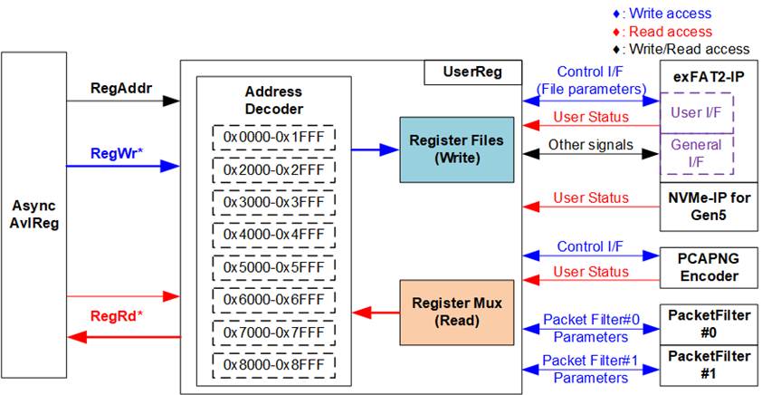
Figure 23 UserReg Interface
The UserReg module comprises three main components: an Address decoder, a Register File, and a Register Mux. The Address decoder interprets the address requested by AsyncAvlReg module and selects the appropriate register for either a write or read transaction. The register address space in UserReg is divided into eight functional regions, as illustrated in Figure 23.
exFAT2-IP, NVMe-IP for Gen5, and Logger Logic
1) 0x0000 – 0x1FFF: Mapped to exFAT2-IP and NVMe-IP for Gen5
2) 0x2000 – 0x2FFF: Mapped to PacketFilter#0
3) 0x3000 – 0x3FFF: Mapped to PacketFilter#1
4) 0x4000 – 0x4FFF: Mapped to Packet Processing and Encoding
System status
5) 0x5000 – 0x5FFF: Mapped to the status of DDR
6) 0x6000 – 0x6FFF: Mapped to EMAC status I/F
7) 0x7000 – 0x7FFF: Mapped to PCIe status I/F
8) 0x8000 – 0x8FFF: Mapped to other interfaces such as IP versions of exFAT2-IP and NVMe-IP for Gen5
The Address decoder uses the upper bits of RegAddr to determine the corresponding hardware. Internally, the Register File operates on a 32-bit data bus. Since full-word writes are used, the write byte enable (RegWrByteEn) is unused in this test system. The CPU accesses the hardware registers using 32-bit address pointers.
For register read operations, a multi-level multiplexers structure is used to select the output data based on the address. The lower bits of RegAddr are utilized within the submodule to choose a specific internal register, while the upper bits are used by UserReg to identify the appropriate submodule for the read. The overall latency for a read operation is four clock cycles. The RegRdValid signal is generated using four D Flip-flops, which are triggered upon a RegRdReq assertion.
Additional information regarding address mapping and register definitions within the UserReg module is provided in Table 2.
Table 2 Register Map
|
Address |
Register Name |
Description |
|
Wr/Rd |
(Label in “ethernetdatalogger.c”) |
|
|
BA+0x0000 – BA+0x1FFF: Signal Interface of exFAT2-IP and NVMe-IP for Gen5 |
||
|
BA+0x0000 |
exFAT2-IP File Name Reg |
[26:0]: Input to U0FName of exFAT2-IP, the first file name to execute commands. |
|
Wr/Rd |
(EXFATFNAME_INTREG) |
|
|
BA+0x0004 |
exFAT2-IP File Length Reg |
[26:0]: Input to U0FLen of exFAT2-IP, the total number of files requested in this command. |
|
Wr/Rd |
(EXFATFLEN_INTREG) |
|
|
BA+0x0008 |
exFAT2-IP Command Reg |
[2:0]: Input to U0Cmd of exFAT2-IP, commands. 000b: Format, 001b: Shutdown, 010b: Write file, 011b: Read file, 100b: Secure Format, 101b: Read file info [8]: Input to U0Req of exFAT2-IP, command request. [9]: Input to U0Abort of exFAT2-IP, abort request. |
|
Wr/Rd |
(EXFATCMD_INTREG) |
|
|
BA+0x0020 |
exFAT2-IP File Size Reg |
[3:0]: Input to U0FSize of exFAT2-IP, configured file size. |
|
Wr/Rd |
(EXFATFSIZE_INTREG) |
|
|
BA+0x0024 |
exFAT2-IP Created Date Reg |
[4:0]: Input to U0FTimeS of exFAT2-IP, second multiplied by 2. [10:5]: Input to U0FTimeM of exFAT2-IP, minute. [15:11]: Input to U0FTimeH of exFAT2-IP, hour. [20:16]: Input to U0FDateD of exFAT2-IP, date. [24:21]: Input to U0FDateM of exFAT2-IP, month. [31:25]: Input to U0FDateY of exFAT2-IP, year. |
|
Wr/Rd |
(EXFATFDATE_INTREG) |
|
|
BA+0x0100 |
exFAT2-IP Status Reg |
[0]: Mapped to U0Busy of exFAT2-IP, busy status. [1]: Mapped to U0Error of exFAT2-IP, error flag. [2]: Overflow flag of PacketHandler. Asserted to 1b when a packet is discarded due to buffer overflow. [3]: Overflow flag of PacketForwarder. Asserted to 1b when a packet is discarded due to buffer overflow. |
|
Rd |
(EXFATSTS_INTREG) |
|
|
BA+0x0110 |
exFAT2-IP Error Type Reg |
[7:0]: Mapped to U0ErrorType[7:0] of exFAT2-IP, indicating error status of exFAT2-IP. |
|
Rd |
(EXFATERRTYPE_INTREG) |
|
|
BA+0x0114 |
NVMe Error Type Reg |
[31:0]: Mapped to U0NVMeErrorType[31:0] of exFAT2-IP, indicating error status of NVMe-IP. |
|
Rd |
(NVMERRTYPE_INTREG) |
|
|
BA+0x0118 |
NVMe Completion Status Reg |
Completion Status from NVMe-IP [15:0]: Mapped to AdmCompStatus[15:0]. [31:16]: Mapped to IOCompStatus[15:0]. |
|
Rd |
(NVMCOMPSTS_INTREG) |
|
|
BA+0x011C |
NVMe CAP Reg |
[31:0]: Mapped to NVMeCAPReg[31:0] of NVMe-IP, capabilities of NVMe. |
|
Rd |
(NVMCAP_INTREG) |
|
|
BA+0x0120 |
exFAT2-IP Test Pin (Low) Reg |
[31:0]: Mapped to U0TestPin[31:0] of exFAT2-IP, reserved for internal use. |
|
Rd |
(EXFATTESTPINL_INTREG) |
|
|
BA+0x0124 |
exFAT2-IP Test Pin (High) Reg |
[63:32]: Mapped to U0TestPin[63:0] of exFAT2-IP, reserved for internal use. |
|
Rd |
(EXFATTESTPINH_INTREG) |
|
|
BA+0x0130 - BA+0x013F |
NVMe Test pin DW0-3 Reg |
[31:0]: Mapped to TestPin[127:0] of NVMe-IP, reserved for internal use. 0x0130: Bits[31:0], 0x0134: Bits[63:32], 0b0138: Bits[95:64], 0x013C: Bits[127:96] |
|
Rd |
(NVMTESTPIN0-3_INTREG) |
|
|
BA+0x0140 |
Total File Capacity Reg |
[26:0]: Mapped to TotalFCap[26:0] of the exFAT2-IP. A non-zero value indicates the number of files supported on the SSD; a zero value means the SSD is not formatted with the exFAT file system by DG’s exFAT-IPs. |
|
Rd |
(TOTALFCAP_INTREG) |
|
|
BA+0x0144 |
Directory Capacity Reg |
[19:0]: Mapped to DirCap[19:0] of exFAT2-IP, maximum number of files for each directory. |
|
Rd |
(DIRCAP_INTREG) |
|
|
BA+0x0148 |
Disk File Size Reg |
[3:0]: Mapped to DiskFsize of exFAT2-IP, file size currently used in this SSD. |
|
Rd |
(DFSIZE_INTREG) |
|
|
BA+0x014C |
Total Count of Files in the Disk Reg |
[26:0]: Mapped to DiskFnum of exFAT2-IP, total count of files in the SSD. |
|
Rd |
(DFNUM_INTREG) |
|
|
Address |
Register Name |
Description |
|
Wr/Rd |
(Label in “ethernetdatalogger.c”) |
|
|
BA+0x0000 – BA+0x1FFF: Signal Interface of exFAT2-IP and NVMe-IP for Gen5 |
||
|
BA+0x0150 |
Current Total Count of Files in the Disk Reg |
[26:0] Mapped to DiskFnumCur of exFAT2-IP, current total count of files in the SSD. |
|
Rd |
(DFNUMCUR_INTREG) |
|
|
BA+0x0158 |
Secure Format Support Reg |
[0]: Mapped to SuppSecureFmt of exFAT2-IP. Asserted to 1b, indicating the Secure Format supported by the device. |
|
Rd |
SECFMTSUPP_INTREG |
|
|
BA+0x0160 |
NVMe LBA Size (Low) Reg |
[31:0]: Mapped to LBASize[31:0] of NVMe-IP, total capacity of SSD in 512-byte unit. |
|
Rd |
(NVMLBASIZEL_INTREG) |
|
|
BA+0x0164 |
NVMe LBA Size (High) Reg |
[15:0]: Mapped to LBASize[47:32] of NVMe-IP, total capacity of SSD in 512-byte unit. [31]: Mapped to LBAMode of NVMe-IP, indicating LBA unit size of SSD. |
|
Rd |
(NVMLBASIZEH_INTREG) |
|
|
BA+0x01A0 |
exFAT2-IP Abort Write File Name Reg |
[26:0]: Mapped to U0AbortFName[26:0] of exFAT2-IP, indicating the last written file name. |
|
Rd |
(EXFATABTFNAME_INTREG) |
|
|
BA+0x0400 |
Timeout Reg |
[31:0]: Mapped to TimeOutSet[31:0] of exFAT2-IP, timeout value for waiting for a response from SSD. |
|
Wr/Rd |
(TIMEOUT_INTREG) |
|
|
BA+0x2000 – BA+0x2FFF: Signal Interface of PacketFilter#0 |
||
|
BA+0x2000 – BA+0x20FF: Control Signal of for Rule#0 of Packet Filter#0 |
||
|
BA+0x2000 - BA+0x2027 |
Rule#0 Header Data of PacketFilter#0 |
The 38-byte header pattern used for packet filtering. This data is compared against byte#0 to #37 of the received packets. 0x2000: [7:0], [15:8], [23:16], [31:24] – byte#0, #1, #2, #3 0x2004: [7:0], [15:8], [23:16], [31:24] – byte#4, #5, #6, #7 … 0x2020: [7:0], [15:8], [23:16], [31:24] – byte#32, #33, #34, #35 0x2024: [7:0], [15:8] – byte#36, #37, |
|
Wr/Rd |
(FLT0HDVAL_INTREG) |
|
|
BA+0x2040 - BA+0x2047 |
Rule#0 Header Byte Enable of PacketFilter#0 |
Byte-enable mask for header comparison. Each bit corresponds to one byte of the header. 0x2040: [0]-[31] – Enable for bytes#0 to #31 0x2044: [0]-[5] – Enable for bytes#32 to #37 0b: Disable byte comparison (bypass), 1b: Enable byte comparison |
|
Wr/Rd |
(FLT0HDMASK_INTREG) |
|
|
BA+0x2100 – BA+0x27FF: Control Signal for Rule#1-#7 of Packet Fitler#0 Note: The base address of Control Signal for Rule#1-#7 of Packet Filter #0 register sets is determined by the offset value from Rule#0 register sets. The specific offset value is assigned using the parameter name ‘FLTRULE_OFFSET’. |
||
|
BA+0x2100 - BA+0x27FF |
Rule#1 - Rule#7 Header Data and Header Byte Enable of PacketFilter#0 |
Each rule configuration consists of 38-byte header data and 38-bit header byte enable. The register mapping for each rule follows the same structure as Rule#0 (BA + 0x2000 – BA + 0x2047), with a fixed offset applied per rule. 0x2100 – 0x2147: Rule#1 configuration, 0x2200 – 0x2247: Rule#2 configuration, … 0x2700 – 0x2747: Rule#7 configuration |
|
BA+0x2800 – BA+0x2FFF: Rule Enable for Packet Filter#0 |
||
|
BA+0x2800 |
PacketFilter#0 Rule Enable |
Controls the enable status of packet filtering rules. Each bit corresponds to one rule of PacketFilter#0. [0]-[7] – Enable of Rule#0 to Rule#7 0b: Disable rule of filtering, 1b: Enable rule of filtering |
|
Wr/Rd |
(FLT0RULEEN_INTREG) |
|
|
BA+0x3000 – BA+0x3FFF: Signal Interface of PacketFilter#1 |
||
|
BA+0x3000 - BA+0x3FFF |
(FLT1HDVAL_INTREG – FLT1RULEEN_INTREG) |
This register range follows the same structure and functionality as BA+ 0x2000 – BA+0x2FFF (PacketFilter#0), but is mapped to PacketFilter#1. |
|
Address |
Register Name |
Description |
|
Wr/Rd |
(Label in “ethernetdatalogger.c”) |
|
|
BA+0x4000 – BA+0x4FFF: Signal Interface of Packet Processing and Encoding |
||
|
BA+0x4000 |
Record Busy Reg |
[0]: Recording status. Asserted to 1b when the incoming packet is in recording. |
|
Rd |
(RECBUSY_INTREG) |
|
|
BA+0x4004 |
Record Stop Reg |
Controls the stop operation of the packet recording process. Wr[0]: Writing 1b triggers the stop operation. This bit is automatically de-asserted by hardware, generating a pulse signal. Rd[0]: Indicate completion of the stop request. This bit is asserted to 1b when the recording process has been stopped. |
|
Wr/Rd |
(RECSTOP_INTREG) |
|
|
BA+0x4008 |
FIFO Reset Reg |
[0]: Reset flag for FIFO for packet recording. Set to 1b to assert a reset and then clear to 0b to de-assert a reset, flushing the FIFO for packet recording process. |
|
Wr/Rd |
(FIFORST_INTREG) |
|
|
BA+0x4010 |
Initial Value of Timestamp (Low) Reg |
[31:0]: Defines the lower 32 bits of the initial 64-bit timestamp used for the packet recording process. |
|
Wr/Rd |
(TIMESTPINITL_INTREG) |
|
|
BA+0x4014 |
Initial Value of Timestamp (High) Reg |
[31:0]: Defines the upper 32 bits of the initial 64-bit timestamp used for the packet recording process. |
|
Wr/Rd |
(TIMESTPINITH_INTREG) |
|
|
BA+0x5000 – BA+0x5FFF: Status Signal of DDR |
||
|
BA+0x5000 |
DDR Controller Status Reg |
[0]: Indicates DDR calibration success. Asserted to 1b when DDR calibration is successful. [1]: Indicates DDR calibration failure. Asserted to 1b when DDR calibration fails. |
|
Rd |
(DDRCTRLSTS_INTREG) |
|
|
BA+0x6000 – BA+0x6FFF: Signal Interface of EMAC Hard IPs |
||
|
BA+0x6000 |
EMAC#0 Reset Reg |
[0]: Reset flag for EMAC#0. Set to 1b to assert a reset and then clear to 0b to de-assert a reset. |
|
Wr/Rd |
(MAC0FWRST_INTREG) |
|
|
BA+0x6004 |
EMAC#0 Status Reg |
[0]: Ethernet MAC link status (0b: Link down, 1b: Link up). [1]: Tx Lock status of Ethernet MAC (0b: Not locked, 1: Locked) [2]: Rx CDR Lock status (0b: Not locked, 1b: Locked) [3]: Rx alignment status (0b: Not aligned, 1b: Aligned) [4]: Rx PCS ready status (0b: Not ready, 1b: Ready) [5]: Remote Fault Code detection (0b: Not detected, 1b: Detected) |
|
Rd |
(MAC0STS_INTREG) |
|
|
BA+0x6010 - BA+0x6017 |
(MAC1FWRST_INTREG – MAC1STS_INTREG) |
This register range follows the same structure and functionality as BA+ 0x6000 – BA+0x6007 (EMAC #0), but is mapped to EMAC #1. |
|
BA+0x7000 – BA+0x7FFF: Signal Interface of PCIe Hard IP |
||
|
BA+0x7000 |
PCIe Status Reg |
[0]: PCIe link status from PCIe Hard IP (0b: Link down, 1b: Link up). [1]: PCIe reset status with active low (0b: IP in reset, 1b: IP active) [5:4]: PCIe link width from PCIe Hard IP (0001b: 1-lane, 0010b: 2-lane, 0100b: 4-lane, 1000b: 8-lane) [10:8]: PCIe link speed of PCIe Hard IP. (0000b: Not linkup, 0001b: PCIe Gen1, 0010b: PCIe Gen2, 0011b: PCIe Gen3, 0111b: PCIe Gen4, 1111b: PCIe Gen5) [21:16]: Current LTSSM state of PCIe Hard IP. Please see more details of LTSSM value in PCIe Hard IP datasheet. |
|
Rd |
(PCIESTS_INTREG) |
|
|
BA+0x8000 – BA+0x8FFF: Signal Interface of PCIe Hard IP |
||
|
BA+0x8000 |
exFAT2-IP Version Reg |
[31:0]: Mapped to IPVersion[31:0] of exFAT2-IP, indicating the version of exFAT2-IP. |
|
Rd |
(EXFAT2VER_INTREG) |
|
|
BA+0x8004 |
NVMe-IP Version Reg |
[31:0]: Mapped to IPVersion[31:0] of NVMe-IP, indicating the version of NVMe-IP. |
|
Rd |
(NVMVER_INTREG) |
|
3 CPU Firmware
3.1 Test Firmware (ethernetdatalogger.c)
Upon system startup, the CPU performs the following steps to complete the initialization process.
1) Initialize UART and Timer settings.
2) The system requires multiple initialization steps, including:
i) Wait for DDR calibration to become ready to use, by monitoring DDRCTRLSTS_INTREG[0]=1b.
ii) Wait for Ethernet #0 link establishment, by monitoring MAC0STS_INTREG[0]=1b.
iii) Wait for Ethernet #1 link establishment, by monitoring MAC1STS_INTREG[0]=1b.
iv) Wait for the PCIe connection to become active by checking PCIESTS_INTREG[0]=1b.
v) Wait for the completion of the exFAT2-IP initialization process, indicated by EXFATSTS_INTREG[0]=0b.
3) CPU determines whether the SSD is formatted with DG’s exFAT-IPs using a supported file size by reading TOTALFCAP_INTREG and DFSIZE_INTREG.
· If the SSD does not use the exFAT file system by DG’s exFAT-IPs with 32 MB file size (TOTALFCAP_INTREG = 0 or DFSIZE_INTREG ≠ 0), present the format menu - offering Format or Secure format (the latter only if supported by the SSD).
The user must choose to execute the Format command or Secure Format; otherwise, the SSD system will offer the Shutdown command.
· Otherwise, display a message informing the user that the SSD uses the exFAT file system by DG’s exFAT-IPs with supported file size (32 MB), along with the file system information such as current file size configuration, maximum number of files in SSD (TOTALFCAP_INTREG), maximum number of files per directory (DIRCAP_INTREG), total files stored in SSD (DFNUM_INTREG), and available space in SSD.
4) The CPU displays the default values of packet filters which enables Rule#0 with disabling header comparison by setting 38-bit header mask to zero. Consequently, every Ethernet packet will be recorded by the system once recording starts. User can select to complete the initialization process using the default parameters or by updating some parameters. The details of how to change the parameter are provided in Set Packet Filter menu (section 3.1.3).
5) The CPU displays the main menu, providing six test options:
· Display Packet Filter Setting
· Display File System Information
· Set Packet Filter
· Set File System
· Start Record
· Shutdown System
Further details for executing each menu are described below.
3.1.1 Display Packet Filter Setting
This menu displays the current settings of the packet filter. The following steps are performed to display the filter settings for each Ethernet MAC interface. In this demo, two EMACs are included, so the steps are executed twice using different base addresses for channel#0 and channel#1.
1) Read the number of enabled packet filter rules from FLT0RULEEN_INTREG + <channel_offset>. Display the number of enabled rules to the user. If at least one rule is enabled, proceed to the next step.
2) Read the configuration of each enabled rule:
· FLT0HDMASK_INTREG + <channel_offset> for the byte-enable mask
· FLT0HDVAL_INTREG + <channel_offset> for the header pattern value
3.1.2 Display File System Information
When this option is selected, the CPU executes the following steps:
1) Display the current file size, which is fixed at 32MB.
2) Display the current created date and time, decoded from internal variables.
3) Display the maximum number of files in the SSD (TotalFCap).
4) Display the maximum number of files per directory (DirCap).
5) Display the total number of existing files (DFnum).
6) Display the total available space in SSD, calculated based on TotalFCap and DFnum.
3.1.3 Set Packet Filter
When this option is selected, the CPU executes the following steps:
1) Prompt the user to confirm the new packet filter configuration. If confirmed, proceed to the next step; otherwise, the operation is cancelled and the system returns to the main menu.
2) Display a message indicating that the system is waiting for parameter sets from the “PacketFilteringConfig” application.
3) Configure packet filtering parameters by writing the received values to the following registers:
· FLT0RULEEN_INTREG + <channel_offset>: Enable packet filtering rules
· FLT0HDMASK_INTREG + <channel_offset>: Byte-enable mask for header comparison
· FLT0HDVAL_INTREG + <channel_offset>: 38-byte header pattern used for packet filtering
4) Return to the main menu.
3.1.4 Set File System
When this test is selected, the Format operation is executed as follows:
1) Display three options: Format execution, Secure Format execution, and No execution. The user selects the corresponding option to proceed or cancel the operation.
2) Prompt the user to set the created date and created time of the empty directories, or skip this step to use default values. After receiving all inputs, determine the final value and write it to EXFATDATE_INTREG.
3) Set the file size to a fixed value of 32 MB and write this value to EXFATFSIZE_INTREG.
4) Set bit[8] and bits[2:0] of EXFATCMD_INTREG to issue the (Secure) Format command. Once the operation starts, the exFAT2-IP asserts the busy status (EXFATSTS_INTREG[0] = 1b).
5) Repeatedly read EXFATSTS_INTREG to check the completion and error conditions:
6) Iterate to read EXFATSTS_INTREG[1:0], verifying the completion condition and error condition.
· If bit[0]=0b, the command is completed. Proceed to the next step.
· If bit[1]=1b, an error is detected. In this case, read error details from EXFATERRTYPE_INTREG and NVMERRTYPE_INTREG, interpret the error type, and display the corresponding error message on the console. The operation is then cancelled.
7) Upon command completion, read the SSD information and display it on the console. The SSD information includes the current file size configuration, the maximum number of files in the SSD (TOTALFCAP_INTREG), the maximum number of files per directory (DIRCAP_INTREG), total number of stored files (DFNUM_INTREG), and available space in SSD.
3.1.5 Record Data
When this option is selected, the CPU performs the data recording operation as follows:
1) Check whether the SSD has reached its maximum capacity.
· If the disk is full, a message is displayed indicating that the disk must be formatted using the “Set File System” menu, and the operation is cancelled.
· Otherwise, proceed to the next step.
2) Reset the recording buffer by writing to FIFORST_INTREG.
3) Set EXFATFNAME_INTREG using the current file index read from DFNUM_INTREG, so that the next file name continues from the existing files.
Example: If DFNUM_INTREG = 9, the last file is F0000009.PCAPNG, and the next file will be F000000A.PCAPNG.
4) Set EXFATFLEN_INTREG to the maximum file length supported by the SSD. This value is calculated based on the remaining file capacity (maximum number of files minus the current number of files).
5) Initialize the timestamp by writing 0 to TIMESTPINITH_INTREG and TIMESTPINITL_INTREG.
6) Set bit[8] and bits[2:0] of EXFATCMD_INTREG to issue the Write File command. The exFAT2-IP asserts the busy status (EXFATSTS_INTREG[0]=1b) when the operation starts.
7) Display a message indicating the key input required to stop recording.
8) The CPU monitors EXFATSTS_INTREG[1:0] to detect completion or errors:
· If bit[0]=0b, the operation is completed. Proceed to step (9).
· If bit[1]=1b, an error is detected. In this case, read error details from EXFATERRTYPE_INTREG and NVMERRTYPE_INTREG, interpret the error type, and display the corresponding error message on the console. The operation is then cancelled.
During recording, if the user requests to stop, set RECSTOP_INTREG[0]=1b to trigger the stop operation. After that, wait until EXFATSTS_INTREG[0]=0b, indicating recording has stopped.
Additionally, DFNUMCUR_INTREG is read every second to display the number of written files on the console.
9) Upon recording completion, read and display the test results:
· Update total file count, reading DFNUM_INTREG.
· Retrieve timer values to compute total time and average transfer speed.
· Retrieve the file name and number of files to compute and display the first and last file names with their directories.
3.1.6 Shutdown System
When this option is selected, the shutdown operation is executed as follows:
1) Prompt the user to confirm the shutdown operation. The user selects the corresponding option to proceed or cancel the operation.
2) Set bit[8] and bits[2:0] of EXFATCMD_INTREG to issue the Shutdown command. The exFAT2-IP asserts the busy status (EXFATSTS_INTREG[0] = 1b) when the operation starts.
3) The CPU waits for command completion or error detection by monitoring EXFATSTS_INTREG[1:0].
· If bit[0]=0b, the operation is completed. Proceed to the next step.
· If bit[1]=1b, an error is detected. In this case, read error details from EXFATERRTYPE_INTREG and NVMERRTYPE_INTREG, interpret the error type, and display the corresponding error message on the console. The operation is then cancelled.
4) Upon command completion, display a message to indicate the SSD has become inactive. No further commands can be issued to the exFAT2-IP.
To resume operation, the system must be power-cycled.
3.2 Function List in Test Firmware
This section describes the list of functions used to operate 100G Ethernet data logger.
|
void change_ftime(void) |
|
|
Parameters |
None |
|
Return value |
None |
|
Description |
Display current created date and time by calling the ‘cur_ftime’ function. Afterward, prompt the user to either keep the current value or input a new one. If a new value is received, validate the range of each field (year, month, date, hour, minute, second), update the global variable (DateTime), and write it to EXFATFDATE_INTREG. |
|
void cur_ftime(void) |
|
|
Parameters |
None |
|
Return value |
None |
|
Description |
Display a fixed message and call the ‘show_ftime’ function to display the current created date and time. |
|
void error_handler(void) |
|
|
Parameters |
None |
|
Return value |
None |
|
Description |
Invoked when an error occurs in the system. The default behavior is to enter an infinite loop, effectively halting all further operation. This function can be customized by the user to implement specific error recovery procedures, such as resetting the system or logging diagnostics. |
|
int format_fat(void) |
|
|
Parameters |
None |
|
Return value |
STATUS_SUCCESS: Operation completed successfully STATUS_ERROR: Error occurred during execution STATUS_CANCEL: Operation is cancelled |
|
Description |
Execute Set File System as outlined in Section 3.1.4. |
|
int record_data(void) |
|
|
Parameters |
None |
|
Return value |
STATUS_SUCCESS: Operation completed successfully STATUS_ERROR: Error occurred during execution |
|
Description |
Execute Record Data as outlined in Section 3.1.5. |
|
int set_packet_filter_param(void) |
|
|
Parameters |
None |
|
Return value |
STATUS_SUCCESS: Operation completed successfully STATUS_INVALIDINPUT: Received invalid input STATUS_CANCEL: Operation is cancelled |
|
Description |
Execute Set Packet Filter as outlined in Section 3.1.3. |
|
void show_dir(unsigned int firstfile, unsigned int lastfile) |
|
|
Parameters |
firstfile: The first file name of the record operation lastfile: The last file name of the record operation |
|
Return value |
None |
|
Description |
Calculate and display the directory and file name (hex format) for both the first and last file, involved in the record operation, using ‘DirCap’ variable to compute the directory path. |
|
void show_error(void) |
|
|
Parameters |
None |
|
Return value |
None |
|
Description |
Read EXFATERRTYPE_INTREG and NVMEERRTYPE_INTREG, interpret an error type, and display detailed error information. |
|
void show_eth_status(unsigned int ch) |
|
|
Parameters |
ch: 0-1 for EMAC I/F #0-#1, respectively |
|
Return value |
None |
|
Description |
Read the current Ethernet MAC status from MAC0STS_INTREG or MAC1STS_INTREG, decode the status bits, and display the result on the console. |
|
void show_file_system_info(void) |
|
|
Parameters |
None |
|
Return value |
None |
|
Description |
Execute Display File System Information as outlined in Section 3.1.2. |
|
void show_ftime(unsigned int time_input) |
|
|
Parameters |
time_input: Encoded date and time value |
|
Return value |
None |
|
Description |
Decodes ‘time_input’ into date (DD/MM/YYYY) and time (HH:MM:SS) format, accounting for the 2-second resolution in the seconds field, and displays the result on the console. |
|
void show_packet_filter_param(void) |
|
|
Parameters |
None |
|
Return value |
None |
|
Description |
Execute Display Packet Filter Setting as outlined in Section 3.1.1. |
|
void show_result(unsigned int stop, unsigned int timeuseh, unsigned int timeusel) |
|
|
Parameters |
stop: Indicate whether a stop was requested timeuseh: Upper 32 bits of elapsed time timeusel: Lower 32 bits of elapsed time |
|
Return value |
None |
|
Description |
Execute the following steps. 1) Calculate total written files, and then display on console. 2) Display total time usage using the ‘show_time’ function. 3) Calculate the last file name. 4) Call ‘show_dir’ to display the file name and directory name of the first file and the last file. 5) Display total file count on the SSD, retrieving from global parameter. |
|
void show_size(unsigned long long size_input) |
|
|
Parameters |
size_input: Data size in bytes |
|
Return value |
None |
|
Description |
Displays the input size in a human-readable format based on its magnitude. If the size is less than 1 GB, it prints the value in megabytes (MB) with three-digit fractional precision. For sizes of 1 GB or more, it displays the size in gigabytes (GB). The output is formatted using six digits for the whole number and three digits for the fractional part. Maximum displayable size is 999999.999 GB. |
|
void show_testpin(void) |
|
|
Parameters |
None |
|
Return value |
None |
|
Description |
Read and display test pin values from EXFATTESTPINH/L_INTREG and NVMETESTPIN0-3_INTREG in hex format on the console. |
|
void show_time(unsigned int timeuseh, unsigned int timeusel) |
|
|
Parameters |
timeuseh: Upper 32 bits of timer value timeusel: Lower 32 bits of timer value |
|
Return value |
None |
|
Description |
Calculate and display elapsed time on the console. Formats time in usec, msec, or sec depending on magnitude, derived from ‘timeuseh’ and ‘timeusel’ values. |
|
int shutdown_dev(void) |
|
|
Parameters |
None |
|
Return value |
STATUS_SUCCESS: Operation completed successfully STATUS_ERROR: Error occurred during execution |
|
Description |
Execute Shutdown System as outlined in Section 3.1.6. |
|
void update_diskparam(void) |
|
|
Parameters |
None |
|
Return value |
None |
|
Description |
Read TOTALFCAP_INTREG, DFSIZE_INTREG, DIRCAP_INTREG, and DFNUM_INTREG, update corresponding internal variables (TotalFCap, DirCap, DFsize, and DFnum), and set ‘filesys_det’ to indicate if the SSD uses the exFAT file system by DG’s exFAT-IPs with supported file size. |
4 Revision History
|
Revision |
Date (D-M-Y) |
Description |
|
1.00 |
3-Apr-26 |
Initial release |