exFAT IP Core for NVMe Datasheet

Core Facts |
|
|
Provided with Core |
|
|
Documentation |
Reference Design Manual Demo Instruction Manual |
|
Design File Formats |
Encrypted netlist file |
|
Instantiation Templates |
VHDL |
|
Reference Designs & Application Notes |
Vivado Project, See Reference Design Manual |
|
Additional Items |
Demo on KCU105, ZCU106, ZCU102, VCU118 |
|
Support |
|
|
Support Provided by Design Gateway Co., Ltd. |
|
Design Gateway Co.,Ltd
E-mail: ip-sales@design-gateway.com
URL: www.design-gateway.com
Features
· Access NVMe SSD as an exFAT system without CPU and external memory required
· Simple user interface
· Direct connection to DG NVMe or NVMeG3 IP
· Achieve comparable write/read performance, compared to raw data format
· Support device capacities: 8 Gigabytes* – 64 Petabytes*
*Gigabyte means 1024x1024x1024 bytes, while Petabyte means 1024x1024x1024x1024x1024 bytes
· Support for 512-byte LBA unit only
· Command support: Format, Secure Format, Write file, Read file, and Shutdown
· Support eight file sizes* - 32MB, 128MB, 512MB, 2GB, 8GB, 32GB, 128GB and 512GB. Some file sizes are not available for certain device capacities.
· Reference design available on KCU105, ZCU102, ZCU106, and VCU118 boards with AB17M2FMC or AB18PCIeX16 adapter board
· Customized services available for the following features:
· Updating supported file sizes, file names, and file extensions
· Additional commands such as Delete file
Table 1: Example Implementation Statistics for Ultrascale device
|
Family |
Example Device |
Fmax (MHz) |
CLB Regs |
CLB LUTs |
CLB |
BRAM Tile |
Design Tools |
|
Kintex-Ultrascale |
XCKU040FFVA1156-2E |
300 |
2724 |
2703 |
601 |
4 |
Vivado2022.1 |
|
Zynq-Ultrascale+ |
XCZU7EV-FFVC1156-2E |
300 |
2724 |
2701 |
561 |
4 |
Vivado2022.1 |
|
Virtex-Ultrascale+ |
XCVU9P-FLGA2104-2L |
300 |
2724 |
2702 |
550 |
4 |
Vivado2022.1 |
Note: Actual logic resource dependent on percentage of unrelated logic
Applications
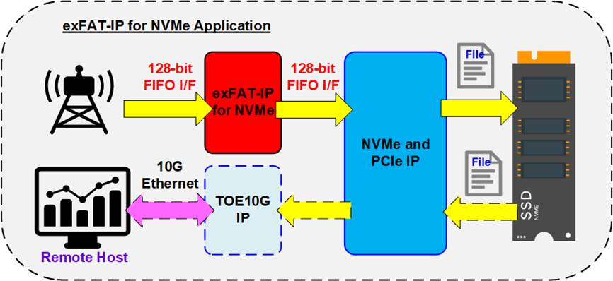
Figure 1: exFAT IP for NVMe Application
The exFAT IP for NVMe is designed to be integrated with DG NVMe IP and lower-layer hardware for the PCIe interface. This IP core offers an ideal solution for accessing NVMe devices using the exFAT file system, delivering full-speed performance comparable to raw data access. This configuration is particularly suited for applications that require recording data to an NVMe device via FPGA, with the data files subsequently being accessible on other hosts, such as PCs, based on the file system format.
As illustrated in Figure 1, the data stream is recorded directly to an NVMe SSD using the exFAT IP system. The read data interface is linked to a TOE10G IP, enabling a remote host to read the recorded file via a 10G Ethernet connection. This comprehensive system is implemented without the need for external memory, such as DDR.
General Description
To avoid these limitations, the exFAT IP for NVMe offers a CPU-less system that allows for writing and reading data in the exFAT file system format at speeds comparable to raw data access. This IP is a top-up module to the NVMe(G3) IP, enabling file system access as opposed to the default raw data mode. The user interface of the exFAT IP for NVMe is designed to be very similar to that of the NVMe(G3) IP for ease of use and includes a control interface and a data interface.
Unlike the NVMe(G3) IP, which operates based on physical parameters, the exFAT IP employs file parameters. For instance, the starting point for data writing/reading is identified by file name rather than physical address, and the data transfer size is determined by the number of files written/read rather than by units of 512 bytes. The exFAT IP introduces five specific commands for NVMe device access: Format, Secure Format, Write file, Read file, and Shutdown.
Similar to the NVMe(G3) IP, the data interface for the exFAT IP utilizes a general FIFO interface. The exFAT IP must also operate on the same user clock as the NVMe(G3) IP, as it lacks asynchronous circuits to interface with user logic and the NVMe(G3) IP.
Additional parameters specific to the exFAT IP include created date, created time, and file size. These are utilized during the execution of the Format, Secure Format, and Write File commands to set the creation date and time for files and directories. The file size parameter, necessary for Format and Secure Format commands, can support up to eight sizes depending on device capacity – ranging from 32 MB to 512 GB, with further details provided in Table 2.
Table 2: Supported file size for each device capacity
|
Device capacity |
32MB(2) |
128MB(2) |
512MB(2) |
2GB(2) |
8GB(2) |
32GB(2) |
128GB(2) |
512GB(2) |
|
8 GB - 16 GB(1) |
Yes |
Yes |
Yes |
Yes |
No |
No |
No |
No |
|
16 GB – 64 GB(1) |
Yes |
Yes |
Yes |
Yes |
Yes |
No |
No |
No |
|
64 GB – 256 GB(1) |
Yes |
Yes |
Yes |
Yes |
Yes |
Yes |
No |
No |
|
256 GB – 1 TB(1) |
Yes |
Yes |
Yes |
Yes |
Yes |
Yes |
Yes |
No |
|
1 TB – 512 TB(1) |
Yes |
Yes |
Yes |
Yes |
Yes |
Yes |
Yes |
Yes |
|
512 TB – 8 PB(1) |
No |
Yes |
Yes |
Yes |
Yes |
Yes |
Yes |
Yes |
|
8 PB – 64 PB(1) |
No |
No |
Yes |
Yes |
Yes |
Yes |
Yes |
Yes |
Note:
(1) The upper limit of device capacity must be less than this value. For example, when the device capacity is 512 TB, the user checks the supported file size from the row corresponding to 512 TB – 2 PB, not from 1 TB – 512 TB.
(2) MB means 1024x1024 bytes. GB means 1024x1024x1024 bytes.
TB means 1024x1024x1024x1024 bytes. PB means 1024x1024x1024x1024x1024 bytes.
Once the Format operation (Standard
or Secure) is completed, the file size becomes fixed and cannot be altered
without rerunning the (Secure) Format command. Executing this command results
in the creation of 512 empty directories on the device, labeled from DIR000 to
DIR1FF. Each directory name consists of three hexadecimal digits that represent
the directory number; for example, DIR0FF corresponds to directory number 255.
Although the (Secure) Format command creates 512 directories, not all directories are utilized. The actual usage of these directories varies, with some remaining empty and others being employed based on specific conditions, as detailed in Table 3.
During the Write file command, a new file is created within a directory. Each filename consists of seven hexadecimal digits, starting from 0000000.BIN stored in DIR000. Subsequent files (0000001.BIN, 0000002.BIN, etc.) are placed in the same directory (DIR000) until the total number of files reaches the maximum capacity allowed per directory (indicated by the DirCap signal). Once this capacity is reached, the next file is stored in the subsequent directory number (DIR001). The maximum number of files per directory varies and is dependent on the device’s capacity, as outlined in Table 3.
Table 3: The maximum number of files per directory (DirCap)
|
Device capacity |
DirCap[19:0] |
Minimum file size |
Used directory |
|
8 GB - 32 GB(1) |
256 (0x00100) |
32MB |
DIR000 - DID003 |
|
32 GB – 128 GB(1) |
512 (0x00200) |
32MB |
DIR000 - DIR007 |
|
128 GB – 512 GB(1) |
1024 (0x00400) |
32MB |
DIR000 – DIR00F |
|
512 GB – 2 TB(1) |
2048 (0x00800) |
32MB |
DIR000 – DIR01F |
|
2 TB – 8 TB(1) |
4096 (0x01000) |
32MB |
DIR000 – DIR03F |
|
8 TB – 32 TB(1) |
8192 (0x02000) |
32MB |
DIR000 – DIR07F |
|
32 TB – 128 TB(1) |
16384 (0x04000) |
32MB |
DIR000 – DIR0FF |
|
128 TB – 512 TB(1) |
32768 (0x08000) |
32MB |
DIR000 – DIR1FF |
|
512 TB – 2 PB(1) |
65536 (0x10000) |
128MB |
DIR000 – DIR0FF |
|
2 PB – 8 PB(1) |
131072 (0x20000) |
128MB |
DIR000 – DIR1FF |
|
8 PB – 32 PB(1) |
262144 (0x40000) |
512MB |
DIR000 – DIR0FF |
|
32 PB – 64 PB(1) |
524288 (0x80000) |
512MB |
DIR000 – DIR0FF |
Note: (1) The
upper limit of device capacity must be less than this value. For example, when the
device capacity is 32 GB, the user checks the value of DirCap from the row corresponding
to 32 GB – 128 GB, not from 8 GB – 32 GB.
Functional Description
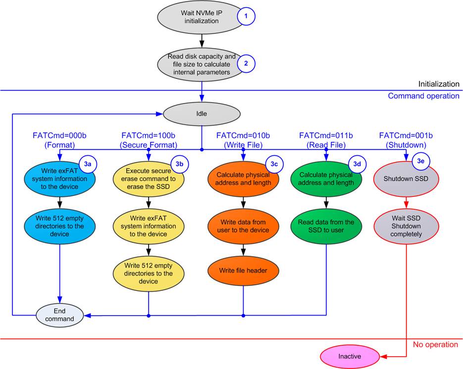
Figure 2: exFAT IP for NVMe Operation
The operational sequence of the exFAT IP Core for NVMe is as follows:
1) The exFAT IP waits until the NVMe(G3) IP completes the initialization of the NVMe device.
2) The exFAT IP issues an Identify command to the NVMe(G3) IP to gather device information such as capacity and support for the Secure Erase command. Subsequently, it updates file information for the device, including the current file size (DiskFSize) and the number of files (DiskFnum). Once the Identify command is completed, the exFAT IP is ready to receive new commands from the user, incluindg Format, Secure Format, Write file, Read file, and Shutdown.
Note: Device file information may be incorrect if not formatted by exFAT IP.
3) The details for each command are described as follows.
a) Format Command: Ideally executed on uninitialized SSD with minimal data, the Format command is quicker than the Secure Format command. It results in the creation of 512 empty directories, and the DiskFnum signal is reset to zero.
b) Secure Format Command: This command serves as an alternative to the standard Format operation, initializing the SSD and erasing all data using the Secure Erase command for enhanced security. This may prolong the operation time. The outcomes include the creation of 512 empty directories and resetting the DiskFnum to zero.
c) Write File Command: Upon selection, the user provides the first file name (UserFName) and the number of files to write (UserFLen). These are converted to a physical address and total transfer size in 512-byte units for the NVMe(G3) IP. The Write command request is then asserted to NVMe(G3) IP, and user data is forwarded until completely transferred. Lastly, the exFAT IP writes the file header to link the user data to each file name.
Note: The file header is written as the final step. If the system is powered down during this command, the file may be lost or corrupted. Also, exFAT IP does not validate input values, so user logic must ensure that inputs are within range.
d) Read File Command: Similar to the Write File command, this begins by calculating the start physical address and total transfer size from user inputs (the first file name and the number of files to read) for setting in NVMe(G3) IP. The Read command request is then asserted, and data is returned from NVMe(G3) IP to the user until completely transferred.
e) Shutdown Command: This must be the final command sent before shutting down the system. It ensures the device is shut down properly. Without executing the Shutdown command, data written may not be flushed from the cache to the flash memory, risking data loss if the system is powered down prematurely. After the Shutdown command, both the NVMe(G3) IP and the device change to an Inactive state.
exFAT IP for NVMe

Figure 3: exFAT IP for NVMe Block Diagram
As illustrated in Figure 3, the exFAT IP consists of three key submodules: the Command processor, the Data Controller, and exFAT RAM. The Command Processor is responsible for processing command requests from the user, while the exFAT Data Controller manages data transfer with the user in both directions. The exFAT RAM module is available to store the system parameters required for the exFAT file system. Further details of each submodule are described as follows.
· Command processor
This module serves as the core processor, controlling the sequence of packet transfer during the execution of each command. It is responsible for setting and monitoring signals from other modules, including exFAT RAM and exFAT Data Controller. Additionally, it encompasses various logics for computing system parameters of the exFAT file system based on user inputs. These parameters include NVMe IP input parameters and constant values assigned to the system data in the SSD. Several parameters are dependent on file size and SSD capacity.
· exFAT RAM
This RAM stores the system parameters for the exFAT file system. It has a size of 1024x128-bit, implemented by BlockRAM.
· Data controller
Though the data interface with the user logic and the NVMe IP utilize FIFO interfaces, the actual data transfer of each interface differs. The data interface with the user logic is employed to transfer raw data within each file. In contrast, the data interface with the NVMe IP encompasses various data types, such as raw data, file entries, and system parameters stored in the exFAT RAM.
DG NVMe IP or NVMeG3 IP
The exFAT IP for NVMe functions as an add-on module to either the NVMe IP or NVMeG3 IP. Both IPs serve as host controllers that facilitate access to NVMe SSD via the PCIe interface, sharing common NVMe features. The distinction between difference the NVMe IP and NVMeG3 IP lies in the implementation of the low layer boundary of the PCIe.
When integrated with NVMe IP, the low layer hardware utilizes the Integrated Block for PCI Express (PCIe hard IP) from AMD Xilinx. Further details about NVMe IP are available in the datasheet, which can be downloaded from the following link:
https://dgway.com/products/IP/NVMe-IP/dg_nvme_ip_data_sheet_en/
Conversely, when exFAT IP is combined with NVMeG3 IP (a version of NVMe IP that includes PCIe Soft IP), it incorporates the Data link layer and portions of the Physical layer of the PCIe protocol within the NVMeG3 IP. Consequently, NVMeG3 IP connects with the Xilinx PCIe PHY to fully implement the PCIe Physical layer. Additional information about NVMeG3 IP can be found in the datasheet available at:
https://dgway.com/products/IP/NVMe-IP/dg_nvmeg3_ip_data_sheet_xilinx_en/
UserLogic
The UserLogic module can be implemented using a simple state machine designed to send commands along with other parameters to the exFAT IP. It employs two FIFOs to act as file data buffers during the execution of Write file and Read file commands. However, the reference design for the exFAT IP includes a CPU that utilizes a Serial console as the user interface. This setup allows for the input of parameters and the display of test results and status information.
Core I/O Signals
Table 4 provides descriptions of all I/O signals for exFAT IP.
Table 4: Core I/O Signals
|
Signal |
Dir |
Description |
|
Clock and Reset |
||
|
RstB |
In |
Synchronous reset signal on the Clk domain, active low. De-assert to 1b after the Clk signal is stable. |
|
Clk |
In |
User clock, output from the same clock source for the user clock of NVMe(G3) IP. The frequency must be greater than or equal to the PCIeClk frequency, the output from the PCIe hard IP (125 MHz for 4-lane PCIe Gen2, and 250 MHz for 4-lane PCIe Gen3). |
|
User Interface (Command) |
||
|
FSize[2:0] |
In |
File size stored in the SSD, which is fixed value for using in (Secure) Format command. It can be set to eight values: 000b: 32MB, 001b: 128MB, 010b: 512MB, 011b: 2GB, 100b: 8GB, 101b: 32GB, 110b: 128GB, 111b: 512GB This input is exclusively utilized for executing the (Secure) Fomat command. Note: 1 MB is 1024x1024 byte and 1 GB is 1024x1024x1024 bytes. |
|
FDateY[6:0] |
In |
Year in created date, count from 1980 (For example, FDateY=39 is year 2019). Note: FDateY, FDateM, FDateD, FTimeH, FTimeM and FTimeS are utilized to set the created time of new files or directories during the execution of the (Secure) Format or Write file command. |
|
FDateM[3:0] |
In |
Month in the created date. Valid range is from 1-12 (1=Jan, 2= Feb, etc). Please refer to the note in the FDateY description. |
|
FDateD[4:0] |
In |
Day in the created date. Valid range is from 1 to 31. Please refer to the note in the FDateY description. |
|
FTimeH[4:0] |
In |
Hour in the created time. Valid range is from 0 to 23. Please refer to the note in the FDateY description. |
|
FTimeM[5:0] |
In |
Minute in the created time. Valid range is from 0 to 59. Please refer to the note in the FDateY description. |
|
FTimeS[4:0] |
In |
Seconds in the created time, multiplied by 2. Valid range is from 0 to 29 (1=2, 2=4, etc.). Please refer to the note in the FDateY description. |
|
UserCmd[2:0] |
In |
Valid when UserReq=1b. The possible values are 000b: Format, 001b: Shut down, 010b: Write file, 011b: Read file, 100b: Secure Format Note: Secure Format requires SuppSecureFmt to be set to 1b to confirm SSD support for Secure Erase. |
|
UserFName[26:0] |
In |
The first file name used to execute commands: Write file or Read file. These file names follow a specific naming rules: 0=’0000000.BIN’, 1=’0000001.BIN’, and so on. The valid range is from 0 to (TotalFCap – 1). During the execution of the Write file command, this value must not exceed the DiskFnum value. When this value is set equal to DiskFnum, the new file name created in the new command request will continue from the latest written file name. Otherwise, the new files from the new command request will overwrite the completely written file from the previous Write file command request. |
|
UserFLen[26:0] |
In |
The total number of files requested in this command, used in Write file and Read file commands. The valid range is from 1 to (TotalFCap – UserFName). |
Signal |
Dir |
Description |
|
User Interface (Command) |
||
|
UserReq |
In |
Set to 1b to send a new command request and de-assert to 0b after the IP starts the operation by setting UserBusy to 1b. This signal can only be asserted when the exFAT IP is in Idle state, indicating by UserBusy being set to 0b. The input parameters required for the corresponding command request must be valid and stable while UserReq is set to 1b. The command parameters include FSize, UserCmd, UserFName, UserFLen, FDateYMD, and FTimeHMS. |
|
UserBusy |
Out |
Set to 1b when the IP is busy for executing the command from the user. |
|
SuppSecureFmt |
Out |
Indicate whether the SSD supports the Secure Format command (0b: not supported, 1b supported). This value becomes valid after the completion of IP initialization. |
|
TotalFCap[26:0] |
Out |
Maximum number of files that can be stored on the SSD. Note: 1) TotalFCap, DiskFsize, and DiskFnum become valid after the completion of exFAT IP initialization, indicated by UserBusy being set to 0b. 2) TotalFCap, DiskFSize, and DiskFnum are invalid if the SSD has never been formatted by exFAT IP. |
|
DirCap[19:0] |
Out |
Maximum number of files that can be stored per directory. This value becomes valid after the completion of IP initialization. |
|
DiskFsize[2:0] |
Out |
File size currently used in the SSD. Please refer to the note in the TotalFCap description. |
|
DiskFnum[26:0] |
Out |
Total count of files stored in the SSD. This signal is also updated after the completion of Write file command. Please refer to the note in the TotalFCap description. |
|
UserError |
Out |
Error flag. Asserted to 1b when UserErrorType is not equal to 0. Once error has been resolved, the user can clear this flag by asserting reset signal to both NVMe(G3) IP and exFAT IP. |
|
UserErrorType[31:0] |
Out |
Error status. [27:0] - Direct mapped to NVMeErrorType[27:0] signal of NVMe(G3) IP. Please see more details in NVMe IP or NVMeG3 IP datasheet. [30] - An error occurs when the SSD capacity is out of supported range, 8 GB – 64 PB. [31] – An error occurs when the LBA unit of SSD is not equal to 512 bytes. |
|
IPVesion[31:0] |
Out |
IP version number |
|
TestPin[63:0] |
Out |
Reserved for DG Internal use. |
|
TimeOutSet[31:0] |
In |
Timeout value to wait for completion from SSD. The time unit is equal to 1/(Clk frequency). When TimeOutSet is equal to 0, Timeout function is disable. This value is generally set to 2 secs. |
|
User Interface (Data) |
||
|
UserFifoWrCnt[15:0] |
In |
Write data counter for the Receive FIFO. Used to monitor the FIFO full status. When the FIFO becomes full, data transmission from the Read file command temporarily halts. If the data count of FIFO is less than 16 bits, the upper bits should be padded with 1b to complete the 16-bit count. |
|
UserFifoWrEn |
Out |
Asserted to 1b to write data to the Receive FIFO when executing the Read file command. |
|
UserFifoWrData[127:0] |
Out |
Write data bus of the Receive FIFO. Valid when UserFifoWrEn is set to 1b. |
Signal |
Dir |
Description |
|
User Interface (Data) |
||
|
UserFifoRdCnt[15:0] |
In |
Read data counter for the Transmit FIFO. Used to monitor the amount of data stored in the FIFO. If the counter indicates an empty status, the transmission of data packets for the Write file command temporarily pauses. When the data count of FIFO is less than 16 bits, the upper bis should be padded with 0b to complete the 16-bit count. |
|
UserFifoEmpty |
In |
Unused for this IP. |
|
UserFifoRdEn |
Out |
Asserted to 1b to read data from the Transmit FIFO when executing the Write file command. |
|
UserFifoRdData[127:0] |
In |
Read data returned from the Transmit FIFO. Valid in the next clock after UserFifoRdEn is asserted to 1b. |
|
NVMe(G3) IP User Interface (Connect to dgIF typeS of NVMe(G3) IP) (Further details of each signal are described in the datasheet of NVMe IP / NVMeG3 IP) |
||
|
NVMeTimeOutSet [31:0] |
Out |
Connect to TimeOutSet of the NVMe(G3) IP |
|
NVMeCmd[2:0] |
Out |
Connect to UserCmd of the NVMe(G3) IP |
|
NVMeAddr[47:0] |
Out |
Connect to UserAddr of the NVMe(G3) IP |
|
NVMeLen[47:0] |
Out |
Connect to UserLen of the NVMe(G3) IP |
|
NVMeReq |
Out |
Connect to UserReq of the NVMe(G3) IP |
|
NVMeBusy |
In |
Connect to UserBusy of the NVMe(G3) IP |
|
NVMeLBASize[47:0] |
In |
Connect to LBASize of the NVMe(G3) IP |
|
NVMeLBAMode |
In |
Connect to LBAMode of the NVMe(G3) IP |
|
NVMeCtmSubm DW0-15[31:0]
|
Out |
Connect to CtmSubmDW0 – CtmSubmDW15 of the NVMe(G3) IP |
|
NVMeError |
In |
Connect to UserError of the NVMe(G3) IP |
|
NVMeErrorType[31:0] |
In |
Connect to UserErrorType of the NVMe(G3) IP |
|
NVMeFifoWrCnt[15:0] |
Out |
Connect to UserFifoWrCnt of the NVMe(G3) IP |
|
NVMeFifoWrEn |
In |
Connect to UserFifoWrEn of the NVMe(G3) IP |
|
NVMeFifoWrData [127:0] |
In |
Connect to UserFifoWrData of the NVMe(G3) IP |
|
NVMeFifoRdCnt[15:0] |
Out |
Connect to UserFifoRdCnt of the NVMe(G3) IP |
|
NVMeFifoEmpty |
Out |
Connect to UserFifoEmpty of the NVMe(G3) IP |
|
NVMeFifoRdEn |
In |
Connect to UserFifoRdEn of the NVMe(G3) IP |
|
NVMeFifoRdData [127:0] |
Out |
Connect to UserFifoRdData of the NVMe(G3) IP |
|
IdenWrEn |
In |
Connect to IdenWrEn of the NVMe(G3) IP |
|
IdenWrDWEn[3:0] |
In |
Connect to IdenWrDWEn of the NVMe(G3) IP |
|
IdenWrAddr[8:0] |
In |
Connect to IdenWrAddr of the NVMe(G3) IP |
|
IdenWrData[127:0] |
In |
Connect to IdenWrData of the NVMe(G3) IP |
Timing Diagram
Initialization
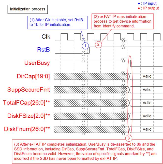
Figure 4: exFAT IP for NVMe Intialization
During the initialization process of the exFAT IP, the following steps are executed.
1) Once the Clk signal is stable, set RstB to 1b to initiate the initialization process of the exFAT IP.
2) During initialization, the exFAT IP sends the Identify command to the NVMe(G3) IP to retrieve SSD information, which is necessary to compute the system parameters for the exFAT file system.
3) Upon completion of the initialization process, UserBusy is set to 0b, and status signals such as DirCap, SuppSecureFmt, TotalFCap, DiskFSize, and DiskFnum become valid for reading. Subsequently, the user can send commands to the exFAT IP via the user interface.
Note: The values of TotalFCap, DiskFSize, and DiskFnum depend on the file size configured during the (Secure) Format command, so these signal values are applicable only when the SSD has been formatted by the exFAT IP.
Format command
If the SSD has never been initialized by the exFAT IP, executing the Format or Secure Format command is necessary as the first command. Otherwise, the Format operation is utilized for following objectives: deleting all files or changing the file size of the SSD. In cases where data security is concerned, it is recommended to use the Secure Format command instead of the Format command. The Format command is optimized to complete the operation quickly, which may result in some data in the SSD not being deleted.
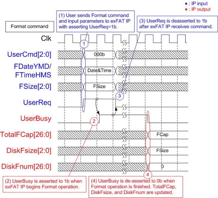
Figure 5: Timing diagram of Format command
During the Format command operation, the following steps are executed.
1) The user sets UserCmd to 000b (Format) along with its corresponding parameter values (FDateYMD: Created data, FTimeHMS: Created time, and FSize: File size), and asserts UserReq to 1b.
2) The exFAT IP initiates the Format operation and sets UserBusy to 1b. The system parameters are computed based on the user-specified parameters and the SSD capacity.
3) Once UserBusy is set to 1b, UserReq can be de-asserted to 0b, indicating the completion of this command request.
4) Upon the completion of the Format command, UserBusy is set to 0b. The SSD is initialized by writing the file system information and creating 512 empty directories (DIR000 – DIR1FF). The values of TotalFCap, DiskFsize, and DiskFnum become valid for reading. DiskFnum is reset to 0 to indicate that the SSD is empty. The created date and time of empty directories are configured by the value of FDataYMD and FTimeHMS.
Secure Format command
The Secure Format command performs the same function as the Format command but employs the Secure Erase command to erases all data. This ensures that all data is thoroughly cleaned and cannot be recovered. In certain SSDs, employing the Secure Erase command can restore the transfer performance of the SSD, which may have degraded after storing a large amount of data.

Figure 6: Timing diagram of Secure Format command
During the Secure Format command operation, the following steps are executed.
1) Verify that the SSD supports the Secure Format command by checking if SuppSecureFmt is set to 1b. If supported, proceed with steps 1) – 4) of the Format command, but set UserCmd to 100b (Secure Format) instead. Note that the operation time of the Secure Format command is longer compared to the Format command.
Write File command
The Write file command can be requested via the User interface. During the execution of the Write file command, raw data from the User data interface is written to the SSD. Without overwritten the available file in the SSD, the file name assigned to UserFName must set by the value of DiskFnum signal. If the SSD is empty, the DiskFnum value equals zero.

Figure 7: Timing diagram of Control Interface for Write file command
To execute two consecutive Write file command requests, the following steps are processed.
1) The user reads DiskFnum and assigns the read value to UserFName for generating the new file name, continuous from the preceding Write file operation. The user sets UserCmd to 010b along with its corresponding parameter values (FDateYMD: Created date, FTimeHMS: Created time, UserFName: Name of the first written file, and UserFLen: Number of written files) and asserts UserReq to 1b. UserFName should be equal to DiskFnum to create new file name, which is the next value from the latest name. UserFLen must not be exceed (TotalFCap – UserFName). As shown in Figure 7, UserFName is equal to 0 when running the first Write file command to an empty SSD.
Note:
i) Setting UserFName value exceeding the value of DiskFnum results in exFAT IP malfunction.
ii) If UserFName value is less than DiskFnum, the files of the preceding Write file command will be overwritten by the new data.
2) The exFAT IP asserts UserBusy to 1b, indicating the initiation of the Write file command.
3) Once UserBusy is set to 1b, the user sets UserReq to 0b to clear the command request. Data is transferred from Use interface to the SSD until completion.
4) UserBusy is de-asserted to 0b upon completion of the Write file command. DiskFnum value is updated to be equal to (UserFName + UserFLen). The created date and time of new files are configured by the values of FDataYMD and FTimeHMS.
5) Without overwritten data from the preceding Write file command, the value of UserFName for the subsequent Write file command must be equal to the value of UserFName.
If N1+N2 does not exceed DirCap value, all files from both Write file command can be stored in the first directory (DIR000), as illustrated in Figure 8.
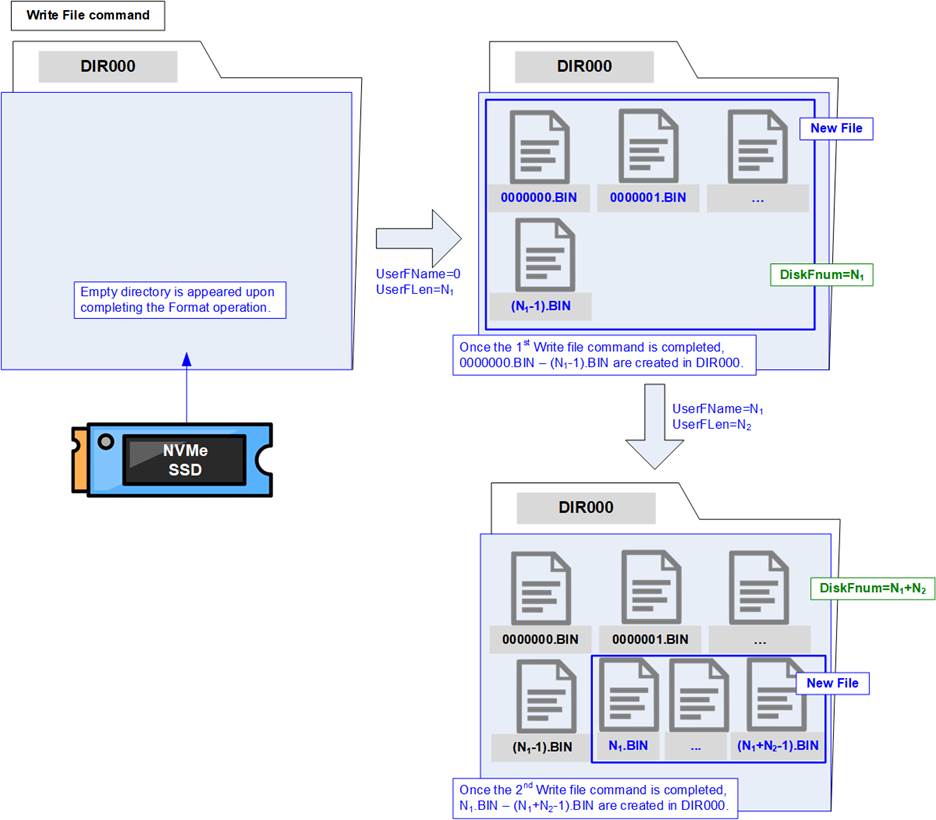
Figure 8: New files created upon completion of the Write file command
The first file name from the first Write file command is 0000000.BIN, and the last file name from the second Write file command is (N1 + N2 – 1).BIN. Each file name is assigned using seven hexadecimal digits.
During executing the Write file command, the User data interface transmits data to the exFAT IP until completion of the command. Similar to the data interface of the NVMe(G3) IP, the data is transferred as 512-byte block size, using 32 clock cycles of 128-bit data size.

Figure 9: Transmit FIFO Interface for Write file command
The sequence for transmitting data via User data interface is as follows.
1) Verify that UserFifoRdCnt[15:5] is not equal to zero, indicating that at least 512-byte of data are available for transfer.
2) The IP asserts UserFifoRdEn to 1b for 32 clock cycles to retrieve 512 bytes of data from the Transmit FIFO.
3) UserFifoRdData becomes valid in the next clock cycle after asserting UserFifoRdEn to 1b, and 32 sets of 128-bit data are continuously transferred.
4) After reading the 32th data (D31), UserFifoRdEn is de-asserted to 0b.
5) Steps 1) – 4) are reiterated to transfer the next 512 bytes of data until the total amount of data matches the specified transfer size in the command (UserFLen).
6) Once all data is completely transferred, UserBusy is de-asserted to 0b.
The total data size for transmission can be computed as UserFLen multiplied by the file size. For example, if UserFLen = N1, the total amount of 128-bit data is equal to N1 x (file size in bytes / 16).
Read File command
The Read file command can be requested via the User interface. During the execution of the Read file command, raw data from the SSD is transmitted to the respective User data interface. It is essential to ensure that the sum of UserFName and UserFLen does not exceed the DiskFnum value to retrieve valid data, instead of dummy data.
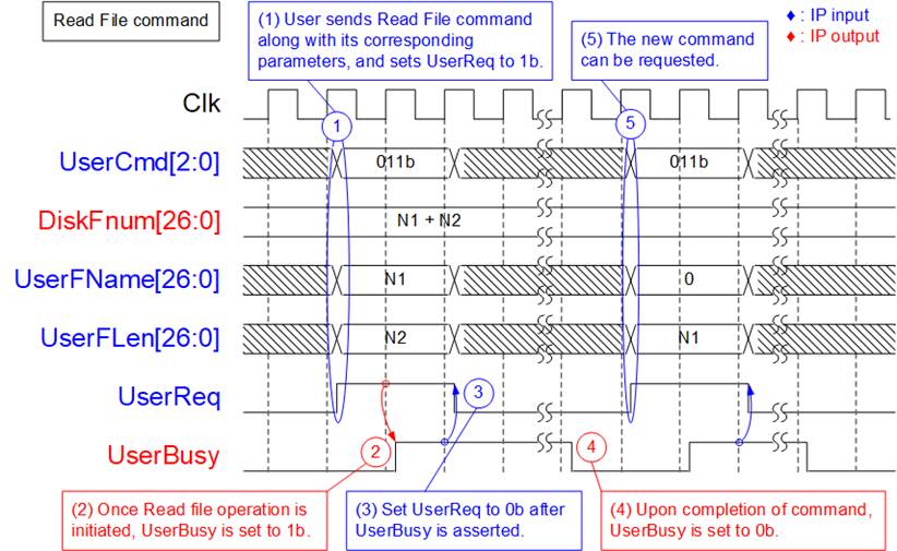
Figure 10: Timing diagram of Control Interface during Read file command
To execute the Read file command request, the following steps are processed.
1) The user sets UserCmd to 011b along with its corresponding parameter values (UserFName: Name of the first read file, and UserLen: Number of read files) and asserts UserReq to 1b. It is crucial to ensure that the value of (UserFName + UserLen) does not exceed DiskFnum.
2) The exFAT IP asserts UserBusy to 1b, indicating the initiation of the Read file command.
3) Once UserBusy is set to 1b, the user sets UserReq to 0b to clear the command request. Data is transferred from the SSD to the User interface until completion.
4) UserBusy is de-asserted to 0b upon completion of the Read file command.
5) The user can then send a new command request to the exFAT IP.
An example of the User Data interface during the execution of Read file command is illustrated in Figure 11.
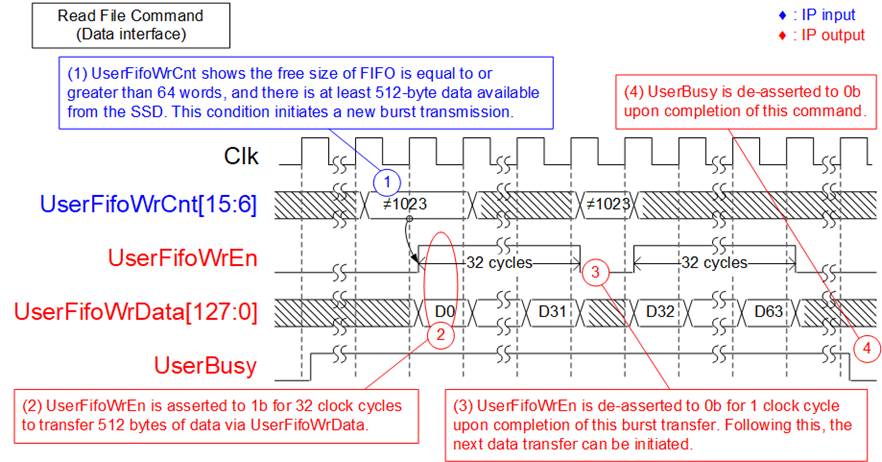
Figure 11: Receive FIFO Interface for Read file command
The sequence for receiving data via the User data interface is as follows.
1) Before initiating a new burst transmission, the exFAT IP checks UserFifoWrCnt[15:6] to verify that there is sufficient free space available in the Receive FIFO, indicated by the condition UserFifoWrCnt[15:6]≠all 1 or 1023. Also, the IP waits until the amount of received data from the SSD reaches at least 512 bytes. Once both conditions are satisfied, the new burst transmission begins.
2) The IP asserts UserFifoWrEn to 1b for 32 clock cycles to transfer 512 bytes of data from the SSD to the User interface.
3) Upon completion of the transfer of 512-byte data, UserFifoWrEn is de-asserted to 0b for one clock cycle. If there is additional data remaining to be transferred, repeat steps 1) – 3) until the total data size matches the specified transfer size in the command (UserFLen).
4) Once all data has been completely transferred, UserBusy is de-asserted to 0b.
The total data size for reception can be computed as UserFLen multiplied by the file size. For example, if UserFLen = N1, the total amount of 256-bit data is equal to N1 x (file size in bytes / 16).
Shutdown command
The Shutdown command is the final command to be sent before the system is powered down. It ensures that any data stored in the SSD’s internal cache is properly written to the flash memory before the shutdown process completes. Once the shutdown operation finishes, the exFAT IP, NVMe(G3) IP, and SSD enter an inactive state. If the SSD is powered down without executing the Shutdown command, any remaining data in the internal cache may be lost.

Figure 12: Timing diagram of Shutdown command
To execute the Shutdown command request, the following steps are processed.
1) Ensure that UserBusy is set to 0b, indicating Idle status. The user sets UserCmd to 010b and asserts UserReq to 1b.
2) The exFAT IP asserts UserBusy to 1b, indicating the initiation of the Shutdown command.
3) Once UserBusy is set to 1b, the user sets UserReq to 0b to clear the command request.
4) UserBusy is de-asserted to 0b upon completion of the Shutdown command. Subsequently, the exFAT IP becomes inactive.
Error
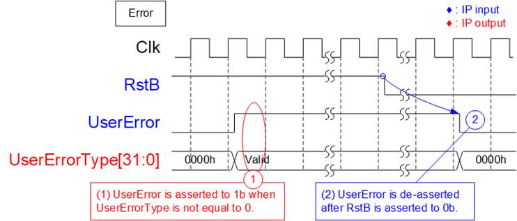
Figure 13: Timing diagram when an error occurs
If an error occurs during the initialization process or while executing certain commands, the UserError flag is set to 1b. To identify the specific type of error, refer to the UserErrorType, which corresponds to an error flag number. The UserError flag is reset exclusively by the RstB signal. Once the issue is resolved, assert RstB to 0b to clear the error flag.
exFAT2 IP Restrictions
1) An NVMe SSD connected to the exFAT IP must be formatted and written exclusively by the exFAT IP. Other host systems are permitted only for read-access.
2) The file size of all files stored in the SSD is configured by FSize during the execution of the (Secure) Format command. Upon completion of the Format operation, the size of the written file is fixed at this configured value. Additionally, the maximum number of files per directory and the maximum number of files for this SSD are displayed to the user output as fixed values. To change the file size, the (Secure) Format command must be executed.
3) Table 3 illustrates the relationship between the DirCap signal and the SSD capacity. User can determine the directory name from the file name using the following equation:
DIR Name = (<FileName>/DirCap) – 1.
For instance, if the SSD capacity is 100G, DirCap equals 512 and the file names stored in each directory are listed as shown in Table 5.
Table 5: The mapping table between file name and directory name
|
File name |
Directory name |
|
0000000.BIN – 00001FF.BIN |
DIR000 |
|
0000200.BIN – 00003FF.BIN |
DIR001 |
|
0000400.BIN – 00005FF.BIN |
DIR002 |
|
0000600.BIN – 00007FF.BIN |
DIR003 |
|
0000800.BIN – 00009FF.BIN |
DIR004 |
|
0000A00.BIN – 0000BFF.BIN |
DIR005 |
|
0000C00.BIN – 0000DFF.BIN |
DIR006 |
|
0000E00.BIN – 0000FFF.BIN |
DIR007 |
4) In Write file command, the newly written file is subsequent to the previously written file by setting UserFName to be equal to DiskFnum. If other values are set, the following situations may occur.
a) If UserFName exceeds DiskFnum, a maloperation will occur. The new files will be lost, and the DiskFnum value will be incorrect.
b) If UserFName is less than DiskFnum, the specified files of the preceding Write file command will be overwritten by the data transfer during the current Write file command. Additionally, if the sum of UserFName + UserFLen (where ‘i’ is a user index) is less than the DiskFnum value, the DiskFnum value will not be updated.
Verification Methods
The exFAT IP Core functionality was verified by simulation and also proved on real board design by using KCU105, ZCU102, ZCU106 and VCU118 boards.
Recommended Design Experience
Experience design engineers with a knowledge of Vivado Tools should easily integrate this IP into their design.
Ordering Information
This product is available directly from Design Gateway Co., Ltd. Please contact Design Gateway Co., Ltd. for pricing and additional information about this product using the contact information on the front page of this datasheet.
Revision History
|
Revision |
Date |
Description |
|
2.00 |
9-May-24 |
Add Secure Format feature |
|
1.06 |
14-Mar-22 |
Support NVMeG3-IP |
|
1.05 |
15-Dec-20 |
Update company info |
|
1.04 |
23-Jul-20 |
Support ZCU106 |
|
1.03 |
18-Feb-20 |
Support VCU118 |
|
1.02 |
10-May-19 |
Update the maximum number of files per directory |
|
1.01 |
22-Mar-19 |
Add DiskFsize and DiskFnum input |
|
1.00 |
11-Jan-19 |
Initial Release |