
Design Gateway Co., Ltd
E-mail: ip-sales@design-gateway.com
URL: design-gateway.com
Features
· Access NVMe SSD as an exFAT file system without requiring CPU or external memory
· Simple user interface
· Direct connection to DG NVMe-IP for Gen5 or muNVMe-IP for Gen5
· Simultaneous SSD access for 1-2 users
· Achieve write/read performance comparable to raw data access
· Support 512-byte LBA units only
· Supports device capacities from 8 Gigabytes* – 64 Petabytes*
*Gigabyte = 10243 bytes, while Petabyte = 10245 bytes
· Command support:
· User#0 (Main user): Format, Secure Format, Write File, Read File, Read File Info, and Shutdown
· User#1 (Sub user): Read File and Read File Info
· Supports eleven file sizes - 32MB, 64MB, 128MB, 256MB, 512MB, 1GB, 2GB, 4GB, 8GB, 16GB, and 32GB
*Availability of file sizes may vary depending on device capacity
· Configurable file name (one-character prefix) and file extension (up to six characters)
· Supports an abort function to stop data transfer during Write File and Read File commands
· Available reference design:
· Agilex7 I-Series development board with AB19-M2PCI and AB20-U2PCI adapter boards
· Customized service available for the following features:
· Increasing user channels
· Updating supported file sizes
· Additional commands (e.g., Delete file)
Table 1 Example Implementation Statistics
|
Family |
Example Device |
User Count |
Fmax (MHz) |
Logic utilization (ALMs) |
Register |
Block Memory bit |
Design Tools |
|
Agilex7 I-Series |
AGIB027R29A1E2VR3 |
1 |
375 |
4,162 |
7,130 |
262,144 |
Quartus 24.3.1 |
|
2 |
375 |
4,437 |
7,620 |
262,144 |
Note: The actual logic resource depends on the percentage of unrelated logic.
Applications
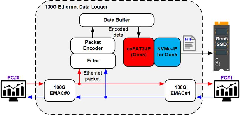
Figure 1 exFAT2-IP for Gen 5 Application
As illustrated in Figure 1, the 100G Ethernet data logger system captures Ethernet packets exchanged between two network devices. The logger passively monitors the communication link and filters packets that match the defined rules, encoding them for storage in the data buffer (DDR or FIFO).
Data output from the buffer is then written to an NVMe Gen5 SSD through the exFAT2-IP and NVMe-IP for Gen5. The combination of these two IP cores enables the sustained full-rate data recording while maintaining a standard file format that can be easily accessed from a PC. This system provides an ideal solution for high-speed network monitoring and protocol analysis applications.
General Description
In conventional systems, a file system is typically implemented via software executed on a CPU, requiring both a processor and external memory to store the firmware. However, this architecture imposes performance limitations due to the overhead introduced by CPU-based file system management. For applications demanding high-throughput file operations, a hardware-based solution is essential.
The exFAT2 IP Core provides a hardware-only implementation of the exFAT file system—eliminating the need for both a CPU and external memory. Implemented entirely in hardware logic, this IP core delivers write and read performance equivalent to raw data access, making it ideal for high-performance storage systems.
The user interface of the exFAT2-IP closely resembles that of the (mu)NVMe-IP, ensuring ease of integration and use. Unlike (mu)NVMe-IP, however, exFAT2-IP updates its index parameters—using file numbers instead of physical numbers—to specify the starting position and transfer size for write and read operations.
The command interface of the exFAT2-IP supports six commands: Format, Secure Format, Write File, Read File, Read File Info, and Shutdown. While User#0 (Main) supports all six commands, User#1 (Sub) supports only Read File and Read File Info.
The data interface follows the same FIFO-based structure as the (mu)NVMe-IP and must operate in the same clock domain to ensure synchronization.
An abort function is also supported, allowing users to cancel an ongoing Write File or Read File command at any time.
Additional parameters are required during the execution of the Format, Secure Format, and Write File commands. Specifically, users must provide the created date and time, which are used to assign timestamps to newly created files and empty directories. For the Format and Secure Format commands, users must also specify the file size for data allocation. The IP core supports eleven predefined file sizes: 32MB, 64MB, 128MB, 256MB, 512MB, 1GB, 2GB, 4GB, 8GB, 16GB, and 32GB. However, the availability of some file sizes depends on the total capacity of the SSD being used. For more information on supported file sizes based on device capacity, refer to Table 2.
Table 2 Supported File Size for each Device Capacity
|
Device capacity |
32MB(2) |
64MB(2) |
128MB(2) |
256MB(2) |
512MB(2) |
1GB(2) |
2GB(2) |
4GB(2) |
8GB(2) |
16GB(2) |
32GB(2) |
|
8 GB - 16 GB(1) |
Yes |
Yes |
Yes |
Yes |
Yes |
Yes |
Yes |
Yes |
No |
No |
No |
|
16 GB – 32 GB(1) |
Yes |
Yes |
Yes |
Yes |
Yes |
Yes |
Yes |
Yes |
Yes |
No |
No |
|
32 GB – 64 GB(1) |
Yes |
Yes |
Yes |
Yes |
Yes |
Yes |
Yes |
Yes |
Yes |
Yes |
No |
|
64 GB – 512 TB(1) |
Yes |
Yes |
Yes |
Yes |
Yes |
Yes |
Yes |
Yes |
Yes |
Yes |
Yes |
|
512 TB – 2 PB(1) |
No |
Yes |
Yes |
Yes |
Yes |
Yes |
Yes |
Yes |
Yes |
Yes |
Yes |
|
2 PB – 8 PB(1) |
No |
No |
Yes |
Yes |
Yes |
Yes |
Yes |
Yes |
Yes |
Yes |
Yes |
|
8 PB – 32 PB(1) |
No |
No |
No |
Yes |
Yes |
Yes |
Yes |
Yes |
Yes |
Yes |
Yes |
|
32 PB – 64 PB(1) |
No |
No |
No |
Yes |
Yes |
Yes |
Yes |
Yes |
Yes |
Yes |
Yes |
Note:
(1) The upper limit of the device capacity refers to the maximum boundary of each range. For example, if the device capacity is 512 TB, users should refer to the row labeled "512 TB – 2 PB" instead of "64 GB – 512 TB" when checking supported file sizes.
(2) Units are defined using binary prefixes: MB = 10242 bytes, GB = 10243 bytes, TB = 10244 bytes, PB = 10245 bytes.
Upon completing the Format operation—whether Standard or Secure—the file size used to access the NVMe SSD is fixed and cannot be changed unless the (Secure) Format command is executed again. This command must be performed as the first operation to initialize the SSD for initial use.
After the format process completes, 512 empty directories are automatically created and named sequentially from DIR000 through DIR1FF. The three digits following “DIR” are hexadecimal values ranging from 000 to 1FF (0 to 511 in decimal). For example, DIR0FF corresponds to directory number 255.
Although all 512 directories are always created during the (Secure) Format process—regardless of device capacity—the maximum number of files per directory (DirCap) depends on the total storage capacity. In addition, the actual number of directories utilized depends on the selected file size, as detailed in Table 3.
When executing the Write File command, the IP generates file names consisting of one configurable prefix character followed by seven hexadecimal digits. For example, if the prefix character is ‘F’, the first file is named F0000000.BIN and is stored in DIR000. If multiple files are specified in the command, subsequent files (F0000001.BIN, F0000002.BIN, etc.) are stored in the same directory (DIR000) until the directory reaches its maximum file capacity (DirCap). Once the directory is full, subsequent files are written to the next available directory, starting with DIR001, and continuing sequentially.
Table 3 The Maximum Number of Files Per Directory (DirCap)
|
Device Capacity |
DirCap[19:0] |
Minimum File Size |
Used Directory |
|
8 GB - 32 GB(1) |
256 (00100h) |
32MB |
DIR000 - DIR003 |
|
32 GB – 128 GB(1) |
512 (00200h) |
32MB |
DIR000 - DIR007 |
|
128 GB – 512 GB(1) |
1024 (00400h) |
32MB |
DIR000 – DIR00F |
|
512 GB – 2 TB(1) |
2048 (00800h) |
32MB |
DIR000 – DIR01F |
|
2 TB – 8 TB(1) |
4096 (01000h) |
32MB |
DIR000 – DIR03F |
|
8 TB – 32 TB(1) |
8192 (02000h) |
32MB |
DIR000 – DIR07F |
|
32 TB – 128 TB(1) |
16384 (04000h) |
32MB |
DIR000 – DIR0FF |
|
128 TB – 512 TB(1) |
32768 (08000h) |
32MB |
DIR000 – DIR1FF |
|
512 TB – 2 PB(1) |
65536 (10000h) |
64MB |
DIR000 – DIR1FF |
|
2 PB – 8 PB(1) |
131072 (20000h) |
128MB |
DIR000 – DIR1FF |
|
8 PB – 32 PB(1) |
262144 (40000h) |
256MB |
DIR000 – DIR1FF |
|
32 PB – 64 PB(1) |
524288 (80000h) |
256MB |
DIR000 – DIR1FF |
Note: (1) The upper limit of the device capacity must be less than the specified boundary. For example, if the device capacity is 32 GB, the appropriate DirCap value should be taken from the row labeled 32 GB – 128 GB, not from 8 GB – 32 GB.
Functional Description
The operation flow of the exFAT2-IP is divided into three phases: Initialization, Command operation, and No operation, as shown in Figure 2.
During the initialization phase, the process is managed by the User#0 I/F, while the User#1 I/F remains inactive until initialization is complete. The initialization process includes the following steps:
1) The exFAT2-IP waits for the (mu)NVMe-IP to complete NVMe SSD initialization.
2) The exFAT2-IP issues an Identify command to the (mu)NVMe-IP to retrieve essential information, including the total SSD capacity and Secure Erase command support status.
3) The exFAT2-IP scans the connected SSD to determine whether it is formatted with the exFAT file system created by DG’s exFAT-IPs.
After the initialization process is completed, all user interfaces remain idle and ready to accept commands from the user. Commands of each User I/F can be issued in parallel, except for the (Secure) Format and Shutdown commands.
All users must return to the Idle state before a (Secure) Format or Shutdown command is requested through User#0 I/F.
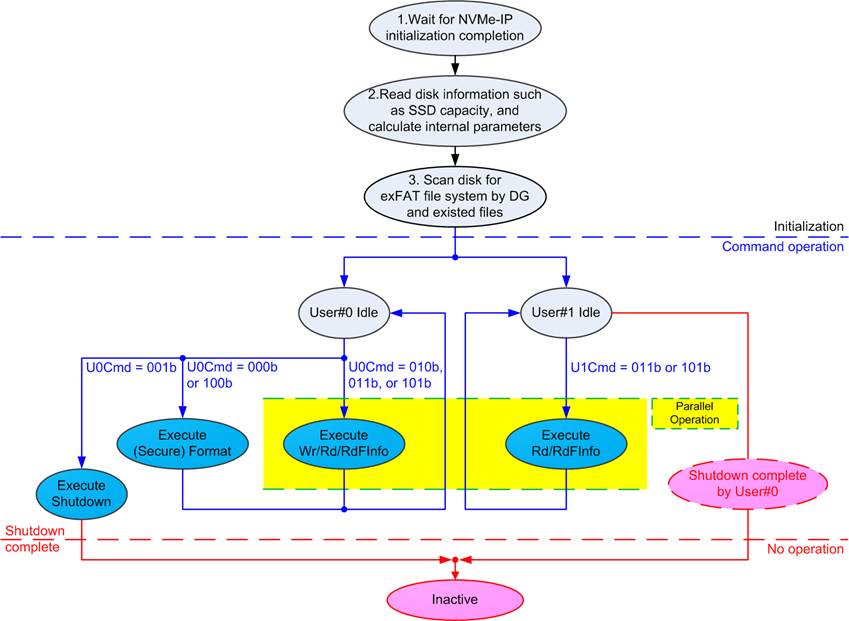
Figure 2 exFAT2-IP Operation
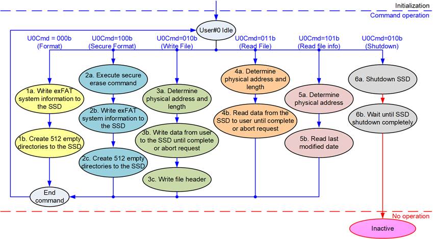
Figure 3 Operation Flow for User#0 Command
For a new SSD that has never been formatted by an exFAT2-IP, the first command issued by the user must be the (Secure) Format, initializing the SSD. The sequence of exFAT2-IP operation is as follows.
1) The Format command must be executed first when using an uninitialized SSD. It performs minimal data writing to initialize the file system, resulting in a much shorter operation time compared to the Secure Format command. Upon completion, 512 empty directories are created on the SSD, and the number of available files (DiskFnum signal) is reset to zero.
2) The Secure Format command is an alternative to the Format command and is used when secure data erasure is required. It performs initialization by erasing all existing data on the SSD using the Secure Erase command (NVMe command), ensuring the deleted data cannot be recovered. This command typically takes longer to complete. After execution, the results are the same as the Format command: 512 empty directories are created, and the DiskFnum signal is reset to zero.
3) To initiate the Write File command, the user sets the first file name (U0FName) and the number of files to write (U0FLen). The exFAT2-IP reads these inputs, calculates the physical address and transfer size, and configures them to the (mu)NVMe-IP accordingly before asserting the Write command request. Data is then transferred from the user to the SSD through the exFAT2-IP and (mu)NVMe-IP until the entire transfer completes or an Abort is received. Finally, the exFAT2-IP writes the file entries for all successfully written files.
Note:
i) File entries are written after the data transfer. If the system is powered down before this step completes, the written files may be lost or corrupted.
ii) Input values must be validated to ensure they fall within the allowable file system limits before issuing the Write File command.
4) To initiate the Read File command, the user must specify the first file name and the number of files to read. The exFAT2-IP determines the corresponding physical address and transfer size, configures the (mu)NVMe-IP, and then asserts the Read command request. Data is transferred from the SSD to the user through the exFAT2-IP and (mu)NVMe-IP until the transfer operation completes or an Abort is received.
5) To execute the Read File Info command, the user specifies the file name. The exFAT2-IP calculates the physical address on the SSD and configures the (mu)NVMe-IP accordingly. After retrieving the file metadata, the exFAT2-IP decodes it and presents the last modified date of the file to the user.
6) The final command before powering down the system must be the Shutdown command. This ensures the SSD is properly powered down, preserving data integrity. Failure to execute the Shutdown command may result in data corruption. Once Shutdown is complete, the exFAT2-IP, (mu)NVMe-IP, and SSD enter the Inactive state and will not accept further commands until a reset is applied to the IP core.
exFAT2 for NVMe-IP Gen5
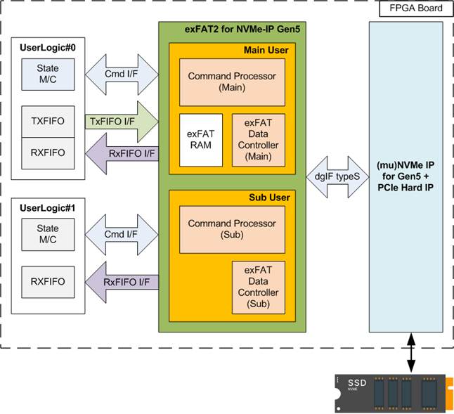
Figure 4 exFAT2 for NVMe-IP Gen5 Block Diagram
As illustrated in Figure 4, the exFAT2-IP architecture is divided into two parallel interfaces: User#0 (Main User) and User#1 (Sub User). The Main User, which supports all six commands, comprises three submodules: the Command Processor, the exFAT Data Controller, and the exFAT RAM. In contrast, the Sub User, which supports only the Read File and Read File Info commands, includes two submodules: the Command Processor and the exFAT Data Controller.
The Command Processor handles command requests from each user, while the exFAT Data Controller manages bidirectional data transfers between the IP and the user. Since the Sub User supports only read operations, its data interface functions in a unidirectional manner—from the exFAT2-IP to the user.
The exFAT RAM module is dedicated to the Main User and is used to store system parameters required for the exFAT file system.
Further details of each submodule are described in the following sections.
· Command Processor
This module acts as the core processor, managing the sequence of packet transfers during command execution. It controls and monitors the signals exchanged with other modules, including the exFAT RAM (available only the Main user) and the exFAT Data Controller.
Additionally, the Command Processor contains logic to calculate system parameters of the exFAT file system based on user inputs. These parameters include configuration settings for the (mu)NVMe-IP and constant values used to write system data to the SSD. Several parameters depend on the selected file size and the total SSD capacity.
· exFAT RAM
This RAM stores the system parameters used by the exFAT file system. It is implemented using embedded block memory with a total size of 256 words, each 512 bits wide.
· Data Controller
Although both the exFAT2-IP’s user logic and (mu)NVMe-IP interfaces use FIFO protocols, the type of their data transfers differs. The exFAT2-IP’s user logic interface is responsible for transferring raw file data, while the (mu)NVMe-IP interface handles a combination of raw file data, file entries, and system parameters retrieved from the exFAT RAM.
DG (mu)NVMe-IP for Gen5
The exFAT2-IP is designed for seamless integration with DG NVMe-IP for Gen5 (single user) or DG muNVMe-IP for Gen5 (multi-user). Both IP cores function as host controllers, enabling high-speed access to NVMe Gen5 SSD through a PCIe interface.
Detailed information about the (mu)NVMe-IP for Gen5 is available at the following links:
NVMe-IP: https://dgway.com/products/IP/NVMe-IP/dg_nvme_datasheet_g5_intel/
For information regarding the muNVMe-IP for Gen5, please contact our sales team.
User Logic
The user interface of the exFAT2-IP is designed for simplicity, enabling implementation with a small state machine to assign parameters and send command requests. Additionally, two FIFOs are integrated for transferring raw data of each file for each user interface (User#0 or User#1). For greater flexibility in configuring test parameters and monitoring test progress, the exFAT2-IP reference design integrates a CPU, allowing users to interact via a JTAG UART.
Core I/O Signals
Descriptions of all I/O signals are provided in Table 4 - Table 5.
Table 4 Core Parameters (Configured via HDL)
|
Name |
Value |
Description |
|
PreFName[7:0] |
ASCII Code |
Specifies the 8-bit subset of UTF-16 (ASCII-compatible only) representing the prefix character used in the file name. Each generated file will include this prefix character as the first character of its file name. For example, if Prefix=’A’, the resulting file names will be: A0000000.BIN, A0000001.BIN, … Invalid values: 00h–1Fh, 22h, 2Ah, 2Fh, 3Ah, 3Ch, 3Eh, 3Fh, 5Ch, 7Ch. If an invalid value is specified, the prefix character will not be included in the file name. |
|
ExtFName[47:0] |
ASCII Code |
Specifies the 8-bit subset of UTF-16 (ASCII-compatible only) representing up to six extension characters used in the file name. Each generated file will include these characters as its file name extension. [7:0] – 6th extension character [15:8] – 5th extension character [23:16] – 4th extension character [31:24] – 3rd extension character [39:32] – 2nd extension character [47:40] – 1st extension character For example, if extension=”PCAP”, the resulting file names will be 0000000.PCAP, 0000001.PCAP, ... Invalid value: 00h–1Fh, 22h, 2Ah, 2Fh, 3Ah, 3Ch, 3Eh, 3Fh, 5Ch, 7Ch. If an invalid value is specified, the corresponding character will not be included in the file name. Note: The system validates extension characters sequentially from the 1st to the 6th character. If an invalid character is detected, that character and all subsequent characters are excluded from the file name. |
Table 5 User I/O Signals (Synchronous with Clk)
|
Signal name |
Dir |
Description |
|
Clock and Reset |
||
|
RstB |
In |
Synchronous reset. Active low. It should be de-asserted to 1b when the Clk signal is stable. |
|
Clk |
In |
User clock sourced from the user clock of the (mu)NVMe-IP for Gen5. The frequency must be equal to or greater than 250 MHz to support 4-lane PCIe Gen5. |
|
User Interface (Command) |
||
|
U0FSize[3:0] |
In |
File size stored in the SSD, which is a fixed value for use in (Secure) Format command. It can be set to eleven values: 0000b: 32MB, 0001b: 64MB, 0010b: 128MB, 0011b: 256MB, 0100b: 512MB, 0101b: 1GB, 0110b: 2GB, 0111b: 4GB, 1000b: 8GB, 1001b: 16GB, 1010b: 32GB This input is exclusively utilized for executing the (Secure) Format command. Note: 1 MB equals 10242 bytes and 1 GB equals 10243 bytes |
|
U0FDateY[6:0] |
In |
Year in the created date, counted from 1980 (For example, U0FDateY=39 represents year 2019). Note: U0FDateY, U0FDateM, U0FDateD, U0FTimeH, U0FTimeM, and U0FTimeS are utilized to set the created time of new files or directories during the execution of the (Secure) Format or Write file command. |
|
U0FDateM[3:0] |
In |
Month in the created date. Valid range is from 1 to 12 (1=Jan, 2= Feb, etc.). See note under U0FDateY description. |
|
U0FDateD[4:0] |
In |
Day in the created date. Valid range is from 1 to 31. See note under U0FDateY description. |
|
U0FTimeH[4:0] |
In |
Hour in the created time. Valid range is from 0 to 23. See note under U0FDateY description. |
|
U0FTimeM[5:0] |
In |
Minute in the created time. Valid range is from 0 to 59. See note under U0FDateY description. |
|
U0FTimeS[4:0] |
In |
Seconds in the created time, multiplied by 2. Valid range is from 0 to 29 (1=2 sec, 2=4 sec, etc.). See note under U0FDateY description. |
|
Signal name |
Dir |
Description |
|
User Interface (Command) |
||
|
U0Cmd[2:0] |
In |
User Command for User#0 I/F. Valid when U0Req=1b. The possible values are 000b: Format, 001b: Shutdown, 010b: Write File, 011b: Read File, 100b: Secure Format, 101b: Read File Info, 110b/111b: Reserved. Note: Secure Format requires SuppSecureFmt = 1b to confirm that the SSD supports the Secure Erase command. |
|
U1Cmd[2:0] |
In |
User Command for User#1 I/F. Valid when U1Req=1b. The possible values are 011b: Read File, 101b: Read File Info |
|
U0-1FName[26:0] |
In |
The first file name (excluding the prefix and file extension) used when executing the Write File, Read File, or Read File Info command. The valid range is 0 to (TotalFCap – 1). This value is converted into a seven-digit hexadecimal number, which is inserted between the prefix character and the file extension in the file name. For example, if U<i>FName=0; where ‘i’ is the user index, the resulting file name will be <prefix>0000000.<extension>. During execution of the Write File command, this value must not exceed the DiskFnum value. If this value is set equal to DiskFnum, the next file name created in the new command request will continue sequentially from the latest written file. Otherwise, the new files from the subsequent Write File command request will overwrite the previously written files. |
|
U0-1FLen[26:0] |
In |
The total number of files requested in this command, used in Write File and Read File commands. The valid range is from 1 to (TotalFCap – U<i>FName; where ‘i’ is the user index). |
|
U0-1Req |
In |
Set to 1b to issue a new command request. This signal must be de-asserted to 0b after the IP begins execution, indicated by U<i>Busy = 1b; where ‘i’ is the user index. This signal can only be asserted when the exFAT2-IP is in the Idle state (U<i>Busy = 0b). All required input parameters—U0FSize, U<i>Cmd, U<i>FName, U<i>FLen, U0FDateYMD, and U0FTimeHMS—must be valid and stable while U<i>Req = 1b. |
|
U0-1Busy |
Out |
Set to 1b when the IP is busy for executing the command from User#0/#1. |
|
U0-1Abort |
In |
Set to 1b for a single clock cycle to abort the ongoing Write File/Read File command operation. The completion of the abort function is indicated by U<i>Busy=0; where ‘i’ is the user index. |
|
U0-1FInfo[31:0] |
Out |
Indicate the modified date and time of the requested file upon the completion of Read File Info command. [4:0] – Seconds, multiplied by 2. Valid range is from 0 to 29 (1=2 sec, 2=4 sec, etc.). [10:5] – Minute. Valid range is from 0 to 59. [15:11] – Hour. Valid range is from 0 to 23. [20:16] – Date. Valid range is from 1 to 31. [24:21] – Month. Valid range is from 1 to 12 (1=Jan, 2= Feb, etc.). [31:25] – Year counted from 1980. |
|
U0AbortFName[26:0] |
Out |
Indicate the last written file name upon the completion of the abort operation for Write File command. |
|
U0AbortCurWrLen [25:0] |
Out |
Indicate the written data size (in 512-byte units) for the last file at the time the Write File command was aborted. |
|
U0-1Error |
Out |
Error flag. Asserted to 1b when U<i>ErrorType (where ‘i’ is the user index) is not equal to 0. Once error has been resolved, the user can clear this flag by asserting reset signal to both (mu)NVMe-IP for Gen5 and exFAT2-IP. |
|
U0-1ErrorType[7:0] |
Out |
Indicates the error status of the system. [0] – An error was detected by the (mu)NVMe-IP for Gen5. Further information can be read from U<i>NVMeErrorType[31:0]; where ‘i’ is the user index. [1] – The SSD capacity is outside the supported range (8 GB – 64 PB). This bit is available only for User#0. [2] – The LBA unit size of the SSD is not 512 bytes. This bit is available only for User#0. [7:3] – Reserved for future use. |
|
U0-1NVMeErrorType [31:0] |
Out |
An error status output from the (mu)NVMe-IP for Gen5. Further details are provided in the UserErrorType signal for the NVMe-IP or U0-1ErrorType signal for the muNVMe-IP. |
|
TimeOutSet[31:0] |
In |
Timeout value specifying the maximum wait time for a completion response from the SSD. The unit of time is based on the period of the Clk signal (1 / Clk frequency). When TimeOutSet is set to 0, the timeout function is disabled. A typical recommended value corresponds to a 2-second timeout. |
|
SuppSecureFmt |
Out |
Indicate whether the SSD supports the Secure Format command (0b: Not supported, 1b: Supported). This signal becomes valid after the completion of IP initialization. |
|
Signal name |
Dir |
Description |
|
User Interface (Command) |
||
|
TotalFCap[26:0] |
Out |
Indicate whether the SSD uses the exFAT file system by DG’s exFAT-IPs and the maximum number of files that can be stored on the SSD. This signal becomes valid after the completion of IP initialization. 0: The SSD does not use the exFAT file system by DG’s exFAT-IPs. Other: The SSD uses the exFAT file system by DG’s exFAT-IPs and the maximum number of files that can be stored on the SSD. Note: DirCap, DiskFsize, DiskFnum, and DiskFnumCur are invalid if the SSD does not use the exFAT file system by DG’s exFAT-IPs. |
|
DirCap[19:0] |
Out |
Indicate maximum number of files that can be stored per directory in the SSD. This signal becomes valid after the completion of IP initialization, and only if the SSD uses the exFAT file system by DG’s exFAT-IPs (TotalFCap ≠ 0). |
|
DiskFsize[3:0] |
Out |
File size currently used in the SSD. This signal becomes valid after the completion of IP initialization, and only if the SSD uses the exFAT file system by DG’s exFAT-IPs (TotalFCap ≠ 0). |
|
DiskFnum[26:0] |
Out |
Total count of files stored in the SSD. This signal becomes valid after the completion of IP initialization, and only if the SSD uses the exFAT file system by DG’s exFAT-IPs (TotalFCap ≠ 0). This signal is also updated upon completion of the Write File command. |
|
DiskFnumCur[26:0] |
Out |
Current total count of files stored in the SSD. This signal becomes valid after the completion of IP initialization and only when the SSD is formatted with the exFAT file system created by DG’s exFAT-IPs (TotalFCap ≠ 0). This signal is updated during execution of the Write File command. Upon completion of the command, this value is synchronized to DiskFnum. It can be used to monitor the number of completed files that are ready for reading via User#1, while User#0 is executing the Write File command. |
|
U0TestPin[63:0], U1TestPin[31:0] |
Out |
Reserved for DG internal use. |
|
IPVersion[31:0] |
Out |
IP version number. |
|
User Interface (Data) |
||
|
U0-1FifoWrCnt[15:0] |
In |
Write data counter for the Receive FIFO. Used to monitor the FIFO full status. When the FIFO becomes full, data transmission from the Read File command temporarily halts. If the data count of FIFO is less than 16 bits, the upper bits should be padded with 1b to complete the 16-bit count. |
|
U0-1FifoWrEn |
Out |
Asserted to 1b to write data to the Receive FIFO when executing the Read File command. |
|
U0-1FifoWrData[511:0] |
Out |
Write data bus of the Receive FIFO. Valid when U0-1FifoWrEn is set to 1b. |
|
U0FifoRdCnt[15:0] |
In |
Read data counter for the Transmit FIFO. Used to monitor the amount of data stored in the FIFO. If the counter indicates an empty status, the transmission of data packets for the Write File command temporarily pauses. When the data count of FIFO is less than 16 bits, the upper bits should be padded with 0b to complete the 16-bit count. Note: For correct operation, the latency between U0FifoRdCnt[15:0] and U0FifoRdEn must be exactly 1 clock cycle. If the system requires additional latency, please contact us for customized adapter logic. |
|
U0-1FifoEmpty |
In |
Unused for this IP. |
|
U0FifoRdEn |
Out |
Asserted to 1b to read data from the Transmit FIFO when executing the Write File command. |
|
U0FifoRdData[511:0] |
In |
Read data returned from the Transmit FIFO. Valid in the next clock after U0FifoRdEn is asserted to 1b. |
|
Signal name |
Dir |
Description |
|
User Interface (Command) - Connected to (mu)NVMe-IP User Interface Note: (1) When connecting to NVMe-IP, each User<signal_name> signal of the NVMe-IP must be connected to the corresponding NVMe0<signal_name> signal of the exFAT2-IP. For example, NVMe0Cmd[2:0] <-> UserCmd[2:0] of NVMe-IP. (2) When connecting to muNVMe-IP, each U0–1<signal_name> signal of the muNVMe-IP must be connected to the corresponding NVMe0–1<signal_name> signals of the exFAT2-IP. For example, NVMe0–NVMe1Cmd[2:0] <-> U0–U1Cmd[2:0] of muNVMe-IP. |
||
|
NVMeTimeOutSet[31:0] |
Out |
Connected to TimeOutSet of the (mu)NVMe-IP. |
|
NVMeLBASize[47:0] |
In |
Connected to LBASize of the (mu)NVMe-IP. |
|
NVMeLBAMode |
In |
Connected to LBAMode of the (mu)NVMe-IP. |
|
NVMe0-1Cmd[2:0] |
In |
Connected to UserCmd of the NVMe-IP or U0-1Cmd of the muNVMe-IP. |
|
NVMe0-1Addr[47:0] |
Out |
Connected to UserAddr of the NVMe-IP or U0-1Addr of the muNVMe-IP. |
|
NVMe0-1Len[47:0] |
Out |
Connected to UserLen of the NVMe-IP or U0-1Len of the muNVMe-IP. |
|
NVMe0-1Req |
Out |
Connected to UserReq of the NVMe-IP or U0-1Req of the muNVMe-IP. |
|
NVMe0-1Busy |
In |
Connected to UserBusy of the NVMe-IP or U0-1Busy of the muNVMe-IP. |
|
NVMe0-1Abort |
Out |
Connected to UserAbort of the NVMe-IP or U0-1Abort of muNVMe-IP |
|
NVMe0-1Error |
In |
Connected to UserError of the NVMe-IP or U0-1Error of the muNVMe-IP. |
|
NVMe0-1ErrorType [31:0] |
In |
Connected to UserErrorType of the NVMe-IP or U0-1ErrorType of the muNVMe-IP. |
|
NVMe0-1FifoWrCnt [15:0] |
Out |
Connected to UserFifoWrCnt of the NVMe-IP or U0-1FifoWrCnt of the muNVMe-IP. |
|
NVMe0-1FifoWrEn |
In |
Connected to UserFifoWrEn of the NVMe-IP or U0-1FifoWrEn of the muNVMe-IP. |
|
NVMe0-1FifoWrData [511:0] |
In |
Connected to UserFifoWrData of the NVMe-IP or U0-1FifoWrData of the muNVMe-IP. |
|
NVMe0FifoRdCnt[15:0] |
Out |
Connected to UserFifoRdCnt of the NVMe-IP or U0FifoRdCnt of the muNVMe-IP. |
|
NVMe0FifoEmpty |
Out |
Connected to UserFifoEmpty of the NVMe-IP or U0FifoEmpty of the muNVMe-IP. |
|
NVMe0FifoRdEn |
In |
Connected to UserFifoRdEn of the NVMe-IP or U0FifoRdEn of the muNVMe-IP. |
|
NVMe0FifoRdData [511:0] |
Out |
Connected to UserFifoRdData of the NVMe-IP or U0FifoRdData of the muNVMe-IP. |
|
NVMe0CompWrLen [47:0] |
In |
Connected to UserCompWrLen of the NVMe-IP or U0CompWrLen of the muNVMe-IP. |
|
NVMe0CtmSubm DW0-15[31:0] |
Out |
Connected to CtmSubmDW0-15 of the NVMe-IP or U0CtmSubmDW0-15 of the muNVMe-IP. |
|
IdenWrEn |
In |
Connected to IdenWrEn of the (mu)NVMe-IP. |
|
IdenWrDWEn[15:0] |
In |
Connected to IdenWrDWEn of the (mu)NVMe-IP. |
|
IdenWrAddr[6:0] |
In |
Connected to IdenWrAddr of the (mu)NVMe-IP. |
|
IdenWrData[511:0] |
In |
Connected to IdenWrData of the (mu)NVMe-IP. |
Timing Diagram
Initialization
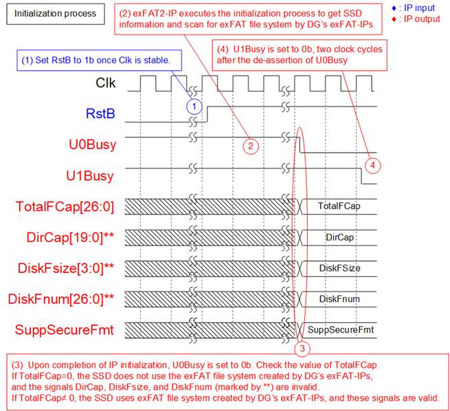
Figure 5 exFAT2-IP Initialization
The initialization process of the exFAT2-IP follows the steps outlined below, as illustrated in the timing diagram:
1) Once the Clk signal is stable, set RstB to 1b to begin initialization of the exFAT2-IP.
2) During initialization, the exFAT2-IP issues an Identify command to the (mu)NVMe-IP to retrieve SSD information necessary for computing the exFAT file system parameters. It also checks whether the SSD is formatted using DG’s exFAT IPs.
3) Upon completion of the initialization process, U0Busy is set to 0b. The user must then check TotalFCap to determine whether the SSD uses the exFAT file system by DG’s exFAT-IPs.
· If TotalFCap = 0, the SSD does not use exFAT file system by DG’s exFAT-IPs. In this case, DirCap, DiskFsize, and DiskFnum are invalid. The user must issue the (Secure) Format command before executing Write File, Read File, or Read File Info command.
· If TotalFCap ≠ 0, the SSD uses exFAT file system by DG’s exFAT-IPs. In this case, DirCap, DiskFsize, and DiskFnum contain valid values.
Note: The values of TotalFCap, DiskFsize, and DiskFnum depend on the file size configured during the (Secure) Format command. These signal values are applicable only when the SSD uses exFAT file system by DG’s exFAT-IPs.
4) The User#1 I/F becomes ready to receive new commands two clock cycles after the readiness of the User#0 I/F, indicated by U1Busy de-asserted to 0b.
Format Command
If the SSD does not use the exFAT file system by DG’s exFAT-IPs, the (Secure) Format command must be executed as the first command. Otherwise, the Format command can be used to delete all files or change the file size configuration of the SSD. When data security is a concern, the Secure Format command is recommended because the standard Format command is optimized for speed and may leave residual data on the SSD.
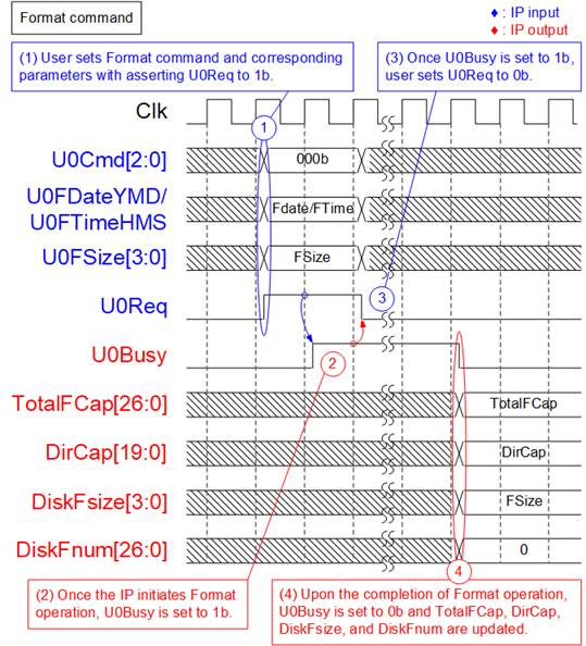
Figure 6 Timing Diagram of Format Command
During the Format command operation, the following steps are executed.
1) The user sets U0Cmd to 000b (Format) and provides the required parameters: U0FDateYMD (created date), U0FTimeHMS (created time), and U0FSize (file size). Then, U0Req is asserted to 1b to issue the command request.
2) The IP begins the Format operation and asserts U0Busy to 1b. It computes the file system parameters based on the user-specified inputs and the SSD’s capacity.
3) Once U0Busy is asserted, U0Req should be de-asserted to 0b to complete the command handshake.
4) When the Format command finishes, U0Busy is de-asserted to 0b. The SSD is then initialized by writing file system information and creating 512 empty directories (DIR000–DIR1FF). At this point, TotalFCap, DirCap, DiskFsize, and DiskFnum are updated. DiskFnum is reset to 0, indicating an empty SSD. The created date and time for the empty directories are set according to the values in U0FDateYMD and U0FTimeHMS.
Secure Format Command
The Secure Format command performs the same function as the standard Format command but uses the Secure Erase command (NVMe command) to ensure that all user data is permanently erased and cannot be recovered. In addition to enhancing data security, executing the Secure Erase command on certain SSDs can help restore degraded write/read performance caused by extensive prior data usage.
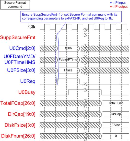
Figure 7 Timing Diagram of Secure Format Command
Before executing the Secure Format command, the user must verify that the SSD supports this operation by confirming that SuppSecureFmt is set to 1b. If support is confirmed, follow the same procedure as steps (1) – (4) of the Format command, but set U0Cmd to 100b (Secure Format).
Note: The Secure Format command may require a significantly longer time to complete compared to the Format command.
Write File Command
The Write File command can be issued through the User#0 I/F. During the execution of the Write File command, raw data from User#0 data interface is written to the SSD. To avoid overwriting existing files on the SSD, U0FName must be set to the current value of DiskFnum signal. If the SSD is empty, DiskFnum equals zero.
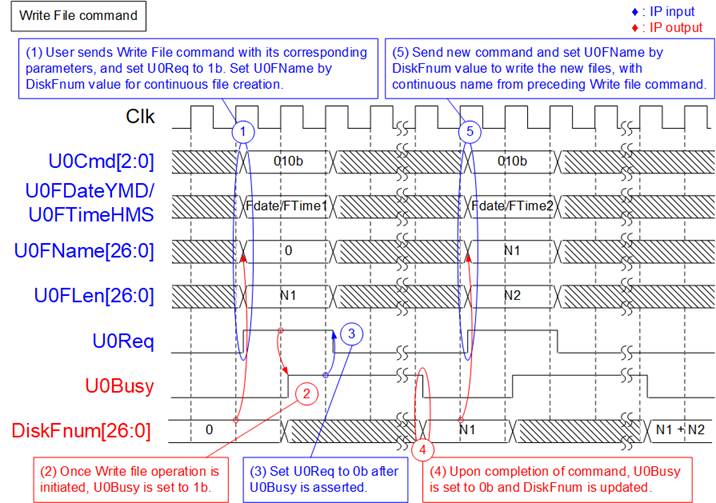
Figure 8 Timing Diagram of User#0 Control Interface for Write File Command
To execute two consecutive Write File command requests, the following steps are processed.
1) Read the value of DiskFnum and assign it to U0FName to ensure the new file names continue sequentially from the last Write operation. Set U0Cmd to 010b and configure the associated parameters: U0FDateYMD (Created date), U0FTimeHMS (Created time), U0FName (First file name), and U0Flen (Number of written files). Then, assert U0Req to 1b. U0FLen must not exceed (TotalFCap – U0FName). As shown in Figure 8, U0FName is set to 0 for the initial Write File command on an empty SSD.
Note:
· Setting U0FName greater than DiskFnum causes exFAT2-IP malfunction.
· Setting U0FName less than DiskFnum causes new data to overwrite previously written files.
2) The IP asserts U0Busy to 1b, indicating the initiation of the Write File command.
3) Once U0Busy is set to 1b, de-assert U0Req to 0b to complete the command request. The IP begins data transfer from user logic to the SSD and continues until the full amount is written.
4) Upon completion, U0Busy is de-asserted to 0b. The value of DiskFnum is updated to U0FName + U0FLen, and the created date/time of the files are set using U0FDateYMD and U0FTimeHMS.
5) For any subsequent Write File operations, U0FName must be set to the updated DiskFnum value to continue generating sequential file names.
If the total number of files from two Write commands (N1 + N2) does not exceed DirCap, all files will be stored in the first directory (DIR000), as illustrated in Figure 9.
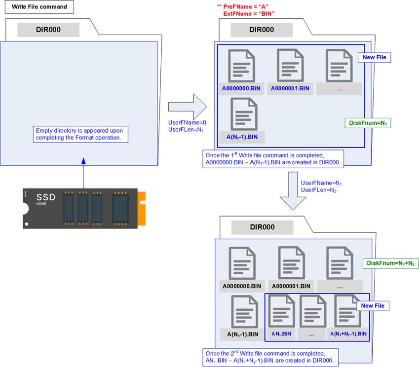
Figure 9 New Files Created Upon Completion of the Write File Command
The first file name generated by the initial Write File command is A0000000.BIN (with PreFName=”A” and ExtFName=”BIN”). The last file name generated by the second Write File command is A<N1 + N2 – 1>.BIN, where N1 and N2 represent the number of files written by the first and second commands, respectively. Each file name consists of one prefix character (configured by PreFName), seven hexadecimal digits, and the file extension (configured by ExtFName).
During the execution of the Write File command, the User#0 data interface transmits data to the exFAT2-IP until the operation completes. Similar to the (mu)NVMe-IP's data interface, data is transferred in 512-byte blocks, using 8 clock cycles of 512-bit data each.
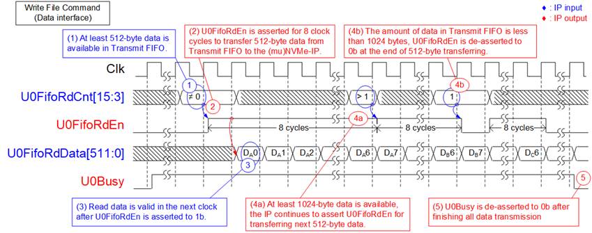
Figure 10 Transmit FIFO Interface for User#0 Write File Command
The data transmission process proceeds as follows:
1) Before starting a new burst transfer, the IP waits until at least 512 bytes of data are available in the Transmit FIFO by monitoring U0FifoRdCnt[15:3], which must not be equal to 0.
2) The IP asserts U0FifoRdEn to 1b for 8 clock cycles to read 512 bytes of data from the Transmit FIFO.
3) UserFifoRdData becomes valid in the next clock cycle after asserting UserFifoRdEn to 1b, and 8 data words are continuously transferred.
4) Each 512-byte block is transferred until the total data size equals the transfer length set by the user. When additional data remains, the IP determines whether to continue the next 512-byte transfer after reading the last data word (Dx7; where x is the index of 512-byte data set). The transfer continuity is based on U0FifoRdCnt[15:3].
a) If U0FifoRdCnt[15:3] indicates that at least 1024 bytes of data are available in the Transmit FIFO, the IP continues asserting U0FifoRdEn to 1b for the next 8 clock cycles (repeat steps (2) – (4)).
b) If U0FifoRdCnt[15:3] indicates that less than 1024 bytes of data remain in the Transmit FIFO, the IP de-asserts U0FifoRdEn to 0b, ending the current 512-byte transfer. The process then repeats from steps (1) – (4).
5) After all data has been completely transferred, U0Busy is de-asserted to 0b.
The total transmitted data size can be calculated as U0FLen x (file size). For example, if U0FLen=N1, the total amount of 512-bit data equals N1 x (file size in bytes / 64).
Note: For correct operations, the latency between U0FifoRdCnt[15:0] and U0FifoRdEn must be exactly 1 clock cycle. If the system requires additional latency, please contact us for customized adapter logic.
Read File Command
The Read File command can be issued through either the User#0 I/F or User#1 I/F. During the execution of the Read File command, raw data from the SSD is transmitted to the corresponding User data interface.
It is essential to ensure that U0FName + U0FLen (for User#0) or U1FName + U1FLen (for User#1) does not exceed the value of DiskFnum value to retrieve valid data.
Figure 11 illustrates an example using the User#1 I/F. The same functionality applies to both User#0 and User#1 I/Fs.
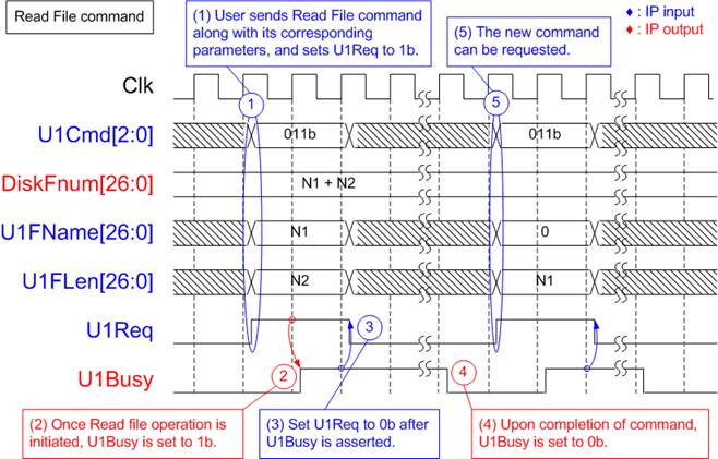
Figure 11 Timing Diagram of User#1 Control Interface for Read File Command
To execute the Read File command request, the following steps are processed.
1) The user sets U1Cmd to 011b along with its corresponding parameter values (U1FName: Name of the first read file, and U1Len: Number of read files) and asserts U1Req to 1b. It is crucial to ensure that the value of (U1FName + U1Len) does not exceed DiskFnum.
2) The exFAT2-IP asserts U1Busy to 1b, indicating the initiation of the Read File command.
3) Once U1Busy is set to 1b, the user sets U1Req to 0b to clear the command request. Data is transferred from the SSD to the User#1 I/F until completion.
4) U1Busy is de-asserted to 0b upon completion of the Read File command.
5) The user can then send a new command request to the exFAT2-IP.
An example of the User#1 Data interface during the execution of Read File command is illustrated in Figure 12.
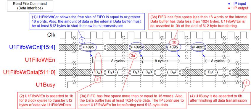
Figure 12 Receive FIFO Interface for User#1 Read File Command
The sequence for receiving data via the User#1 data interface is as follows.
1) Before initiating a new burst transfer, the exFAT2-IP checks U1FifoWrCnt[15:4] to ensure there is sufficient free space in the Receive FIFO#1, which is indicated by the condition U1FifoWrCnt[15:4]≠all 1s or 4095. The IP also waits until at least 512 bytes of data have been received from the SSD. Once both conditions are satisfied, the new burst transfer begins.
2) The IP asserts U1FifoWrEn to 1b for 8 clock cycles to transfer 512 bytes of data from the SSD to the User#1 I/F.
3) Each 512-byte block is transferred until the total data size equals the transfer length specified by the user. If more data remains, the IP determines whether to continue the next 512-byte transfer after writing the last data word (Dx7; where x is the index of 512-byte data block) of the current transfer. The continuity of the transfer is determined based on U1FifoWrCnt[15:4], which monitors the available space in Receive FIFO#1:
a) If there is sufficient free space (more than or equal to 16 words or 1024 bytes) in Receive FIFO#1 and at least 1024 bytes of data are available in the Data Buffer, the IP continues asserting U1FifoWrEn to 1b for the next 8 clock cycles (repeat steps (2) – (3)).
b) If less than 1024 bytes of free space remain in Receive FIFO#1 or less than 1024 bytes of data are available in the Data Buffer, the IP de-asserts U1FifoWrEn to 0b, ending the current 512-byte transfer. The process then repeats from steps (1) – (3).
4) After all data has been completely transferred, U1Busy is de-asserted to 0b.
The total received data size can be calculated as U1FLen x (file size). For example, if U1FLen=N1, the total amount of 512-bit data equals N1 x (file size in bytes / 64).
Write File and Read File Commands in Parallel
The user can issue command requests simultaneously to both the User#0 I/F and User#1 I/F, except for the Format, Secure Format, or Shutdown command. Figure 13 illustrates an example of executing the Write File command on the User#0 I/F and the Read File command on the User#1 I/F simultaneously.
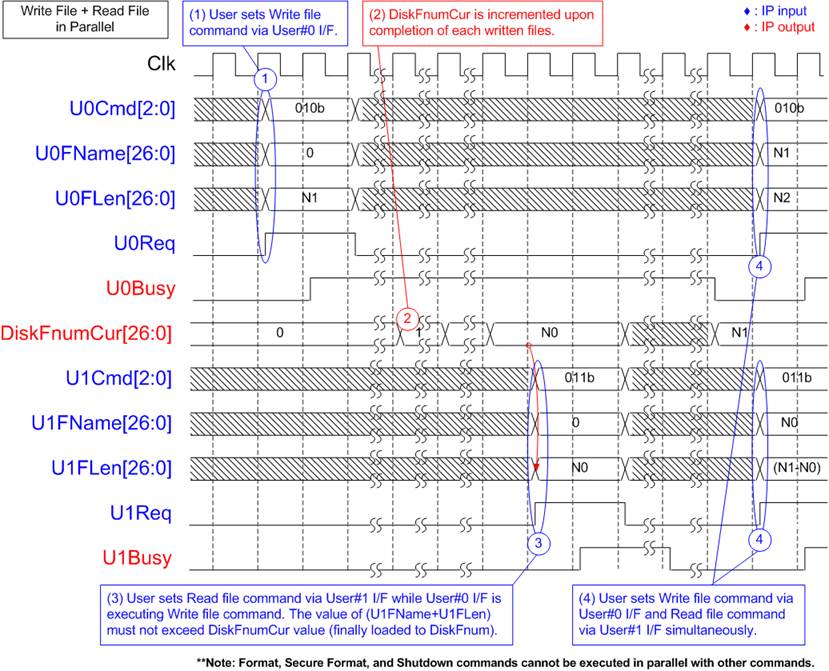
Figure 13 Control Interface Timing Diagram when Executing Command Simultaneously
1) The User#0 I/F initiates the Write File command, setting U0FName to zero to create new files on an empty SSD. The DiskFnumCur value is initially zero for the empty SSD.
2) During the execution of the Write File command, DiskFnumCur is incremented to indicate the completion of each file written to the SSD.
3) Let’s assume DiskFnumCur equals N0, indicating the SSD contains N0 files. The User#1 I/F can then send a Read File command to retrieve all N0 files from the SSD, setting U1FName to 0 and U1FLen to N0. It is crucial at this stage to ensure that the value of (U1FName + U1FLen) does not exceed the DiskFnumCur value.
4) Upon completion of the User#0 I/F operation, both DiskFnumCur and DiskFnum are updated to N1. Subsequently, new command requests for both the User#0 I/F and User#1 I/F can be sent.
Abort for Write and Read File Commands
The abort operation is triggered by asserting U<i>Abort (‘i’ refers to the user index) for one clock cycle during execution of a Write or Read File command. The abort operation is completed when U<i>Busy (‘i’ refers to the user index) is de-asserted to 0b. Timing diagrams illustrating the abort operation for Write and Read File commands are shown in Figure 14 and Figure 15, respectively.
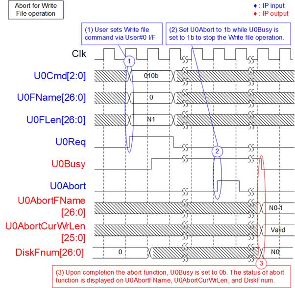
Figure 14 Timing Diagram of Abort During User#0 Write File Command
The abort operation for the Write File command is as follows.
1) The User#0 I/F initiates the Write File command, setting U0FName to 0 to begin writing new files to an empty SSD. For an empty SSD, the initial value of DiskFnum is also zero.
2) While the Write File operation is in progress (U0Busy = 1b), the user asserts U0Abort to 1b for a single clock cycle to request cancellation.
3) Upon completion of the abort process, U0Busy is de-asserted to 0b. The name of the last written file is shown on U0AbortFName, which equals (DiskFnum – 1). The actual size of valid data written to this file is indicated by U0AbortCurWrLen, expressed in 512-byte units. Any remaining portion of the file contains undefined or dummy data.
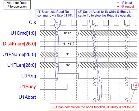
Figure 15 Timing Diagram of Abort During User#1 Read File Command
The abort operation for the Read File command is as follows.
1) The User#1 I/F initiates the Read File command.
2) While the Read File operation is in progress (U1Busy = 1b), the user sets U1Abort to 1b for a single clock cycle to request cancellation.
3) Upon completion of the abort function, U1Busy is set to 0b. After this point, no additional data is transferred via the User#1 data interface.
The User#0 I/F also supports the Read File command. To cancel the command on this interface, the user asserts U0Abort to 1b, following the same procedure as shown in Figure 15.
Read File Info Command
In some applications, the SSD records new data by overwriting existing files without executing the Format command. To differentiate newly written files from older ones, the created date and time are updated accordingly.
To retrieve the created/modified date and time of a specific file, the user can issue a Read File Info command and specify the requested file name via both the User#0 I/F and User#1 I/F. Figure 16 illustrates an example of sending a Read File Info command via the User#1 I/F.
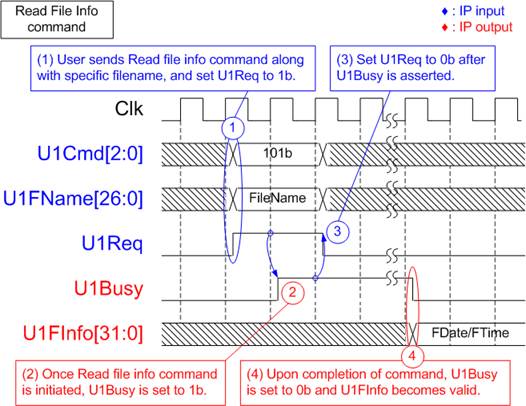
Figure 16 Timing Diagram of User#1 Read File Info Command
1) The user sets U1Cmd to 101b and configures the required parameter (U1FName: the name of the requested file). The user then asserts U1Req to 1b. It is crucial to ensure that the value of U1FName does not exceed DiskFnum.
2) The IP asserts U1Busy to 1b, indicating the initiation of the Read File Info command.
3) Once U1Busy is set to 1b, the user sets U1Req to 0b to clear the command request.
4) U1Busy is de-asserted to 0b upon completion of the Read File Info command. U1FInfo becomes valid, containing the created or modified date and time of the specified file.
Shutdown Command
The Shutdown command should be the final command issued before powering down the system. It ensures that any data temporarily stored in the SSD's internal cache is safely written to flash memory. Once the shutdown process is complete, the exFAT2-IP, (mu)NVMe-IP, and connected SSD enter an inactive state. If the system is powered off without issuing the Shutdown command, cached data may be lost.

Figure 17 Timing Diagram of Shutdown Command
To execute the Shutdown command request, the following steps are processed.
1) Ensure that both U0Busy and U1Busy are set to 0b, indicating Idle status. The user sets U0Cmd to 001b and asserts U0Req to 1b.
2) The exFAT2-IP asserts U0Busy to 1b, indicating the initiation of the Shutdown command.
3) Once U0Busy is set to 1b, the user sets U0Req to 0b to clear the command request.
4) Upon completion of the Shutdown command, U0Busy is de-asserted to 0b. The exFAT2-IP and (mu)NVMe-IP become inactive.
Error
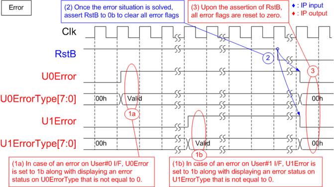
Figure 18 Timing Diagram When an Error Occurs
If bit[0] of U<i>ErrorType is set to 1b, the error originates from the (mu)NVMe-IP. In this case, additional details can be obtained from U<i>NVMeErrorType signal (where ‘i’ is the user index), which specifies the exact NVMe-related error.
The U<i>Error flag can only be cleared by asserting RstB to 0b. Once the issue has been resolved, reset the IP by driving RstB to 0b to clear the error status and resume normal operation.
exFAT2-IP Restrictions
1) An NVMe SSD connected to the exFAT2-IP must be formatted and written exclusively by the exFAT2-IP. Other host systems are permitted only in read-only mode.
2) The file size of all files stored in the SSD is configured by U0FSize during the execution of the (Secure) Format command. Upon completion of the Format operation, every file written to the SSD will use this fixed size. Additionally, the maximum number of files per directory (DirCap) and the maximum number of files for this SSD (TotalFCap) are reported to the user output as fixed values. To change the file size, the (Secure) Format command must be re-executed.
3) The relationship between DirCap and SSD capacity is detailed in Table 3. The directory containing a given file can be determined using the following equation:
Directory Name = <FileName> / DirCap.
For instance, if the SSD capacity is 100G and DirCap = 512, then directory allocation for file names will follow the structure shown in Table 6.
Table 6 The Mapping Table Between File Name and Directory Name
|
File Name |
Directory Name |
|
0000000.BIN – 00001FF.BIN |
DIR000 |
|
0000200.BIN – 00003FF.BIN |
DIR001 |
|
0000400.BIN – 00005FF.BIN |
DIR002 |
|
0000600.BIN – 00007FF.BIN |
DIR003 |
|
0000800.BIN – 00009FF.BIN |
DIR004 |
|
0000A00.BIN – 0000BFF.BIN |
DIR005 |
|
0000C00.BIN – 0000DFF.BIN |
DIR006 |
|
0000E00.BIN – 0000FFF.BIN |
DIR007 |
4) When executing the Write File command, the user must set U0FName equal to DiskFnum to ensure that the new file is appended after the last written file. Violating this rule may lead to the following issues:
· If U0FName > DiskFnum, an operation error occurs. The newly written files will be lost, and DiskFnum will become incorrect.
· If U0FName < DiskFnum, existing files from the previous Write File command will be overwritten. Additionally, if (U0FName + U0Flen) < DiskFnum, the DiskFnum value will not be updated.
Verification Methods
The exFAT2 IP Core for Gen5 functionality was verified by simulation and also proved on real board design by using Agilex7 I-Series development kit.
Recommended Design Experience
Experienced design engineers with knowledge of Quartus tools should easily integrate this IP into their design.
Ordering Information
This product is available directly from Design Gateway Co., Ltd. For pricing and additional information about this product, please refer to the contact information on the front page of this datasheet.
Revision History
|
Revision |
Date (D-M-Y) |
Description |
|
1.00 |
17-Feb-26 |
Initial release |