2.3 Network properties settings
7.4 Load FPGA network parameters
7.8 Enable showsessionparams Mode
This document provides detailed instructions to demonstrate the use of the QUIC Client 10Gbps IP core (QUIC10GC-IP) on our reference design, referred to “QUIC10GC-IP Reference Design”, using the FPGA Evaluation Board. The QUIC10GC-IP is used as a medium to transfer data within a secure connection following the QUIC transport protocol version 1 standard (RFC9000). This process involves handling the TLS 1.3 handshake and dealing with data encryption and decryption.
The reference design uses the QUIC10GC-IP and manages the application layer of the IP. It is tailored to test the IP functionality, help users understand how to use the IP, and to offer flexibility for users in case they need to modify the design. There are two main applications demonstrated in this reference design: one is HTTP/3, as the application layer to streamline the HTTP data, and the other is a unique application protocol designed by an organization to use with their application.
This instruction will explain step-by-step how users can utilize the QUIC10GC-IP through our reference design for uploading and downloading data from two examples. aioquic is the first example, used to perform as a server using the HTTP/3, and the results are similar to those achieved by a web browser. Also, MsQuic is employed as a server to show the transfer performance using the unique application protocol.
Following our document guidelines, this document will describe how to set up the environment for the test, provide more details about our reference examples (aioquic and MsQuic), and instruct and show the results of the test, respectively.
1 Environment Setup
To run the QUIC10GC-IP demo, please prepare following test environment.
1) FPGA development board.
2) FPGA development boards.
3) Test PC with 10 Gigabit Ethernet or connecting with 10 Gigabit Ethernet card.
4) 10 Gb Ethernet cable:
a) Agilex7 I-Series board, use a QSFP+ to four SFP+ cable.
5) Micro USB cable for JTAG connection connecting between FPGA board and Test PC.
6) Quartus Programmer and Nios Command Shell, installed on PC.
7) Demo configuration file (To download these files, please visit our website at www.design-gateway.com).
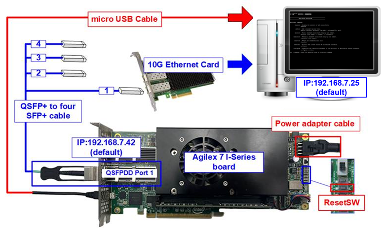
Figure 1 QUIC10GCIP demo environment on Agilex7 I-Series board
2 PC Setup
Before running demo, please check the network setting on PC. The example of setting 10 Gb Ethernet card is described as follows.
2.1 IP setting
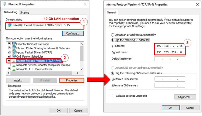
Figure 2 Setting IP address for PC
1) Open Local Area Connection Properties of 10 Gb connection, as shown in the left window of Figure 2.
2) Select “TCP/IPv4” and then click Properties.
3) Set IP address = 192.168.7.25 and Subnet mask = 255.255.255.0, as shown in the right window of Figure 2.
2.2 Speed and duplex settings

Figure 3 Set Link Speed = 10 Gbps
1) On Local Area Connection Properties window, click “Configure”, as shown in Figure 3.
2) On Advanced Tab, select “Speed and Duplex”. Set the value to “10 Gbps Full Duplex” for running 10 Gigabit transfer test, as shown in Figure 3.
2.3 Network properties settings
Some of network parameter settings may affect network performance. The example of network properties setting is as follows.
1) On “Interrupt Moderation” window, select “Disabled” to disable interrupt moderation which would minimize the latency during transferring data, as shown in Figure 4.
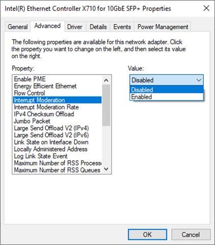
Figure 4 Interrupt Moderation
2) On “Interrupt Moderation Rate” window, set the value to “OFF”, as shown in Figure 5.
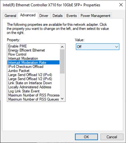
Figure 5 Interrupt Moderation
Rate
3) On “Jumbo packet” window, set the value to “9014 Bytes”, as shown in Figure 6.
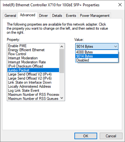
Figure 6 Jumbo packet
4) On “Receive Buffers” window, set the value to the maximum value, as shown in Figure 7.
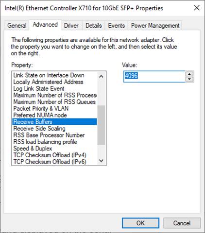
Figure 7 Receive Buffers
5) On “Transmit Buffers” window, set the value to the maximum value, as shown in Figure 8.
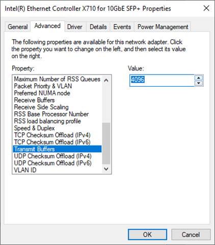
Figure 8 Transmit buffers
3 aioquic server
aioquic is an open-source implementation of QUIC and HTTP/3 in Python, which can be found using this link: github.com/aiortc/aioquic. However, this development requires some changes to run our demonstration. The following points highlight where the modifications are made.
1) Replaced ‘examples/templates/index.html’, which is the index html of aioquic, with Design Gateway’s html file.
2) Added sample key and certificate files*, named tls_key.pem and tls_cert.pem, respectively, in ‘tests/’ directory.
3) Added an html file, called ‘tests/httpEcho.html’, to show one functionality of the aioquic.
This reference uses aioquic version 1.0.0, which we are grateful for the development and publication, and all of these modifications are included in our aioquic folk in this repository github.com/design-gateway/aioquic. If you have any questions regarding their core, please kindly direct them to the aioquic development team.
Remark
* Since QUIC10GC-IP supports two signature algorithms, rsa_pss_rsae_sha256 and ecdsa_secp256r1_sha256, the key and certificate must correspond to either an RSA key or an ECDSA key using the secp256r1 curve. By default, the provided example key and certificate use RSA. For testing with ECDSA, alternative files are also provided as ecdsa_key.pem and ecdsa_cert.pem. To switch the aioquic server to use ECDSA, replace tls_key.pem and tls_cert.pem with ecdsa_key.pem and ecdsa_cert.pem, respectively.
3.1 Run aioquic
‘examples/http3_server.py’ is used as an example to run a QUIC demo server. To run this server, certain parameters are required, all of which you can find using the help command, as shown in Figure 9. This information shows the available options and usage instructions for the aioquic HTTP/3 server, allowing users to configure parameters such as the TLS certificate, private key, host address, port, and other settings relevant to the QUIC server operation.
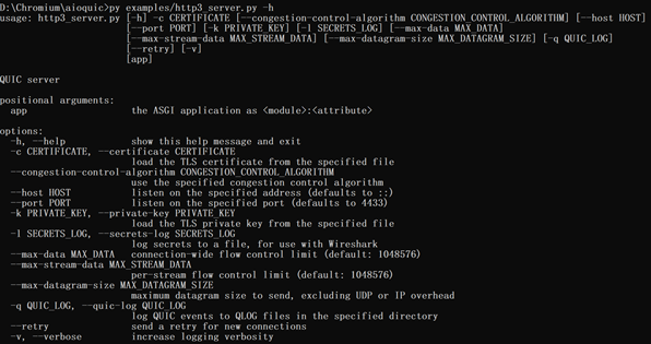
Figure 9 aioquic console with the help command
As depicted in, an aioquic server is operated by running the python file on the terminal with certain options. This example uses the provided key and certificate files, binds to an existed address on the machine, and logs the secrets in a text file.

Figure 10 Example of running the aioquic HTTP/3 server
3.2 Run Chrome web browser
A typical web browser can be used to communicate with the aioquic server. The process involves using the GET method to download data from the server and using the POST method to upload data to the server. To access the demo server running on the local machine, launch Chromium or Chrome with the following command:
<path to chrome.exe> --enable-experimental-web-platform-features \
--ignore-certificate-errors-spki-list=<SPKI> \
--origin-to-force-quic-on=<server ip:server port> \
url path

Figure 11 Example command line to run Chrome with aioquic server
The certificate used in this demonstration is self-signed, meaning it was not issued by a certification authority (CA). When attempting to access the server with a self-signed certificate, the web browser may generate a certificate unknown error and terminate the connection. To bypass certificate errors, users can run the Chrome browser from the command prompt with the ‘--ignore-certificate-errors-spki-list’ flag, specifying the certificate's SPKI (Subject Public Key Info). This allows Chrome/Chromium to accept the self-signed certificate as valid. Users can generate the SPKI with the following command:
openssl x509 -noout -pubkey -in tls_cert.pem |^
openssl pkey -pubin -outform der |^
openssl dgst -sha256 -binary |^
openssl base64

Figure 12 Example command line to calculate public key hash from certificate
When launching Chrome with the ‘--ignore-certificate-errors-spki-list’ flag, users may encounter a message indicating that Chrome is running with an unsupported command-line flag. The flag ‘--ignore-certificate-errors-spki-list’ is used to bypass SSL/TLS certificate errors by specifying a list of SPKI hashes. This can be useful for testing purposes but is not recommended for regular use due to potential security and stability risks.

Figure 13 Example of encountering the --ignore-certificate-errors-spki-list flag
Remark: Our tested web browser is Google Chrome version 125.0.6422.113.
3.3 Download with method get
The aioquic demo example supports HTTP/3, allowing users to download data from the aioquic server using a web browser via the GET method. To download data, the URL required as an input must follow this format:
https://ip:port/length
Where ip represents server’s IP address in dot-decimal notation.
port represents server’s port number.
length represents data length in byte (or leave blank to get the homepage).
For example, if the server’s IP address is 192.168.7.25 and the port number is 4433, the URL must be https://192.168.7.25:4433/ to establish a secure connection and display the aioquic homepage in the web browser, as illustrated in Figure 15.

Figure 14 aioquic console when the client downloads the homepage
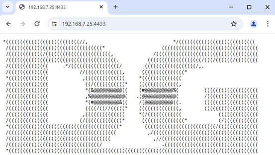
Figure 15 Download the index html using web browser
To download data with a specific length, user adds a size in byte unit at the end of the URL. For example, https://192.168.7.25:4433/500 is used as the URL to download 500-byte data, which will be displayed in the web browser, as shown in Figure 16.

Figure 16 Download data pattern shown in the web browser

Figure 17 aioquic console when the client downloads data pattern
3.4 Upload with method POST
aioquic also offers a method to upload data to an aioquic server. By using a web browser, an application named ‘httpEcho.html’ is provided for uploading data in a secure connection with an aioquic server.
Users can open the webpage of this application by simply dragging and dropping the html file into a browser. At this point, a user interface appears which allows users to set parameters, such as server’s IP address and port number, and to input the data message to be uploaded to the server, as shown in Figure 18. After setting the inputs, users press the “Send” button in order to send a POST command to the aioquic server with the URL endpoint “/echo”.
Although the aioquic doesn’t support a direct POST method by showing the data message at their side, it returns the data message back to the sender, the web browser in this case. As a result, the echoed data is displayed in the web browser, as depicted in Figure 19.
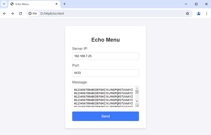
Figure 18 Upload a message via a web browser
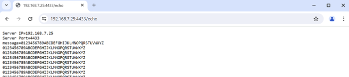
Figure 19 Echo Data from the aioquic server shown in the web browser

Figure 20 aioquic console when the client uploads data
4 MsQuic server
Another QUIC software implementation used in our reference is MsQuic, developed by Microsoft. Their work is an open-source software project, written in C and published in the following website: github.com/microsoft/msquic. We use MsQuic version 2.3.5 and would like to thank Microsoft and the MsQuic team for the development of MsQuic. There is no modification of MsQuic required to run with our demonstration, but we included a folk of MsQuic as a reference branch that we use in this repository: github.com/design-gateway/msquic. If you have any questions regarding their core, please kindly direct them to the MsQuic development team.
There are several application examples offered by MsQuic, but for our reference, an application called ‘secnetperf’ is applied to run with our demo due to the fact that it is optimized for the high-performance data transfer. For this reason, it uses its own application protocol rather than using the HTTP/3 protocol. Please follow MsQuic’s guidelines to set up the application.
To run an MsQuic server using the secnetperf application, secnetperf.exe is called with two options – one is the IP address to bind the server to, and the other is the profile setting of this application, configured for maximum performance in this example. After running the binary file, the message displaying “Started!” is shown as a result, and there will be no other messages thereafter. The example of running the MsQuic is illustrated in Figure 21.

Figure 21 MsQuic server application console
At this point, a client running the secnetperf application can be connected to the server. To run the client, four options are used in this example: “target” being the IP address of the server to be connected to, “exec” being the same setting as of the server, “up/down” being the length of the upload or download, and “ptput” being the setting to print throughput information. The example of the client console uploading data from the server is shown in Figure 22, while the example of downloading data to the server is shown in Figure 23.

Figure 22 MsQuic client application console uploading data

Figure 23 MsQuic client application console downloading data
5 QUIC10GC demo setup
1) Make sure power switch is off and connect power supply to FPGA development board.
2) Connect USB cables between FPGA board and PC via micro-USB ports.
3) Turn on power switch for FPGA board.
4) Open Quartus Programmer to program FPGA through USB-1 by following step.
i. Click “Hardware Setup…” to select
- AGI FPGA Development Kit [USB-1] for Agilex7 I-series
ii. Click “Auto Detect” and select FPGA number.
iii. Select FPGA device icon (Agilex7 I-series).
iv. Click “Change File” button, select SOF file in pop-up window and click “open” button.
v. Check “program”.
vi. Click “Start” button to program FPGA.
vii. Wait until Progress status is equal to 100%.
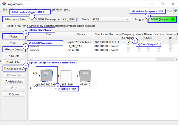
Figure 24 FPGA Programmer for Agilex
After program SOF file complete, Quartus Prime will show popup message of Intel FPGA IP Evaluation Mode Status as shown in Figure 2‑3. Please do not press cancel button.
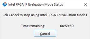
Figure 25 Intel FPGA IP Evaluation Mode Status
6 Nios II Command Shell
Users can set the parameters or run the download and upload applications by using the following commands. The QUIC10GC demo commands and their usages will be displayed, as shown in Figure 26. Detailed information about each command is described in topic 7.
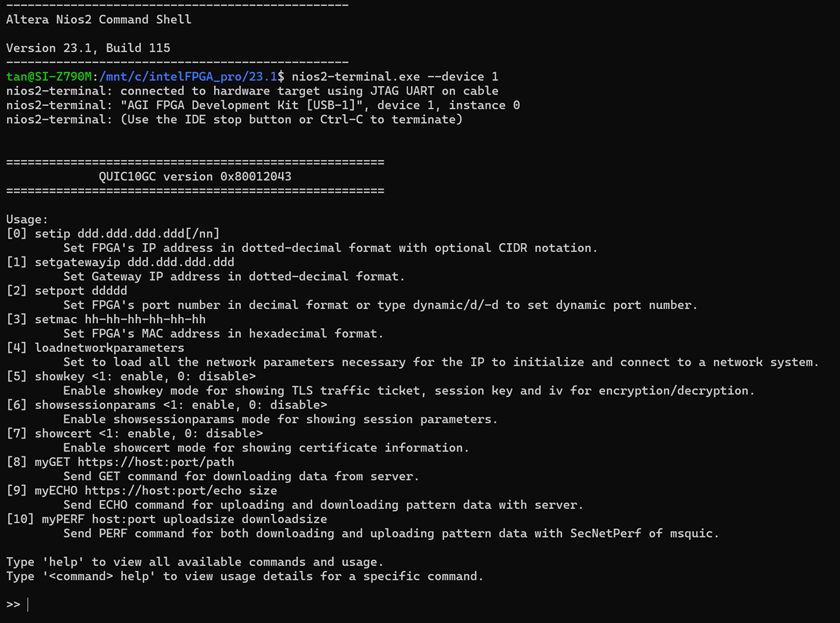
Figure 26 Nios II Command Shell
7 Command detail
7.1 Set Gateway IP Address
command> setgatewayip ddd.ddd.ddd.ddd
This command is used to set the Gateway IP address in dotted-decimal format. The default Gateway IP address is 0.0.0.0, which indicates to the IP that there is no valid Gateway IP address. Users can input the setgatewayip command followed by a valid IP address, as shown in Figure 26.
7.2 Set FPGA IP Address
command> setip ddd.ddd.ddd.ddd[/nn]
This command is used to set the FPGA’s IP address in dotted-decimal format, with an optional subnet mask in CIDR notation. The default FPGA IP address is 192.168.7.42/24. Users can input the setip command followed by a valid IP address (e.g., 192.168.7.42) or an IP address with a CIDR suffix (e.g., 192.168.7.42/24), as shown in Figure 26. If the CIDR value is omitted, the default subnet mask of /24 is applied.
7.3 Set FPGA MAC address
command> setmac hh-hh-hh-hh-hh-hh
This command is used to set the FPGA’s MAC address in hexadecimal format. The default FPGA’s MAC address is 80-11-22-33-44-55, which is a unicast MAC address.
7.4 Load FPGA network parameters
command> loadnetworkparameters
This command is used to load all the network parameters necessary for the IP to initialize and connect to a network system. These include the Gateway IP address, FPGA’s IP address, and FPGA’s MAC address. The QUIC10GC-IP must have all network parameters loaded at least once after a power-on reset or when the IP core system reset is active.
7.5 Set FPGA Port Number
command> setport ddddd
This command is used to set the static port number of FPGA in decimal format. By default, the FPGA’s port number is set to be dynamic. Dynamic ports range from 49152 to 65535. Users can enable dynamic port again after specifying a port number by using “setport dynamic” command, as shown in Figure 26. It is worth noting that this command is not listed in the necessary network parameters, and therefore, it can be used to change the port number at any time before opening connection.
7.6 Enable showkey mode
command> showkey <1: enable, 0: disable>
This command is used to enable the showkey mode. When the showkey mode is enabled, the TLS traffic ticket for encryption/decryption is displayed on the serial console, as shown in Figure 27. Users can utilize the TLS traffic ticket in the (Pre)-Master-Secret log file for Wireshark*, enabling them to decrypt transferred data between the client and server.
*Wireshark, a network packet analyzer tool used for network troubleshooting, analysis, and security purposes.

Figure 27 Serial console when the showkey mode is enabled
7.7 Enable showcert mode
command> showcert <1: enable, 0: disable>
This command is used to enable the showcert mode. When the showcert mode is enabled, the server’s certificate stored in RAM called CertRam is displayed on the serial console, as shown in Figure 28. The certificate information is displayed in hexadecimal format, which corresponds to the result obtained by using openssl command: openssl x509 -in tls_cert.pem -outform der | hexdump -C, as shown in Figure 29.
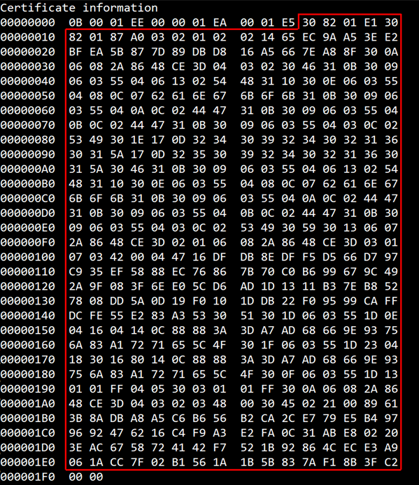
Figure 28 Serial console when the showcert mode is enabled
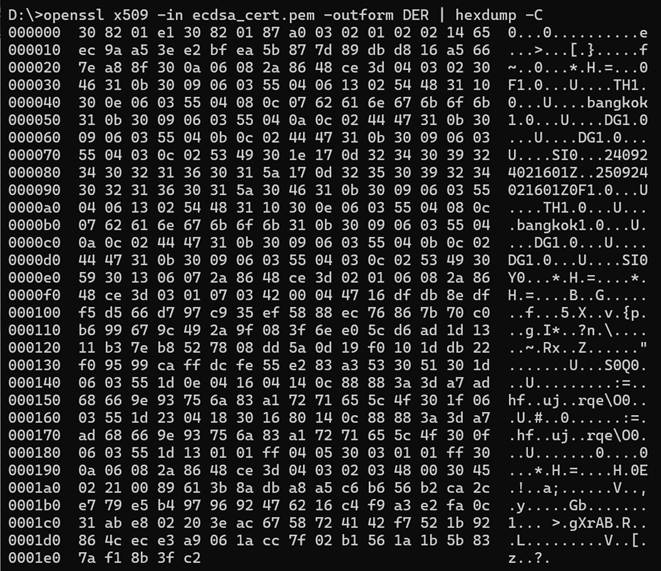
Figure 29 Certificate information from the openssl command
7.8 Enable showsessionparams Mode
command> showsessionparams <1: enable, 0: disable>
This command is used to enable the session parameter display mode. When the showsessionparams mode is enabled, the negotiated QUIC transport parameters and session resumption ticket are displayed on the serial console after a successful handshake, as shown in Figure 30. Users can utilize this information to verify the 0-RTT resumption parameters stored for future connections and debug QUIC transport layer configuration.
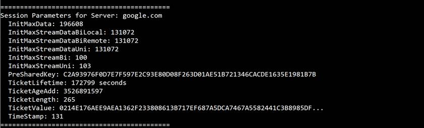
Figure 30 Serial console when the showsessionparams mode is enabled
7.9 GET method
command> myGET https://hostname[:port]/urlpath
Where hostname represents the server’s domain name or IP address in dot-decimal notation
port represents the server’s port number
urlpath represents the path to the desired resource on the server
This command simulates the HTTP/3 GET method to request a resource from the server. The myGET function is called to extract the server’s IP address and the server’s port number.
If the user specifies a domain name as the hostname and it matches an existing hostname-to-IP mapping, the corresponding IP address from the table is used and the hostname is set as server name indication (SNI) for QUIC10GC. If no match is found, the function prompts the user to manually enter the IP address. This IP address is then used as the network parameter and saved into the hostname-to-IP mapping for future use. If the user does not specify a port number, a default value “443” is used.
For testing with aioquic server, the length of the download data can be specified at urlpath. If the length parameter is left blank, the aioquic server will return the homepage, and the received data will be displayed on the serial console, as shown in Figure 31.
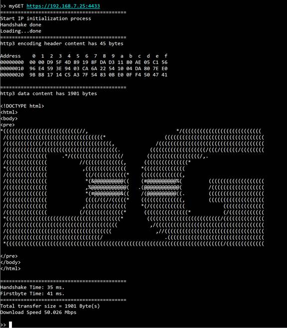
Figure 31 Serial console when downloading the homepage
On the other hand, if the length parameter is specified, the aioquic server will be requested to return data of the specified length. Once the data is downloaded, it will be displayed on the serial console, as shown in Figure 32, with the following limitation: if the total received data exceeds 4kB (4096 bytes), only the first 4096 bytes will be displayed. In all cases, the total length of the received data and the download speed will be displayed on the serial console.
Due to the aioquic specification, the maximum data length is capped at 50MB for testing with the aioquic server. If users request to download data exceeding this limit, the software will retrieve only 50MB from the server.
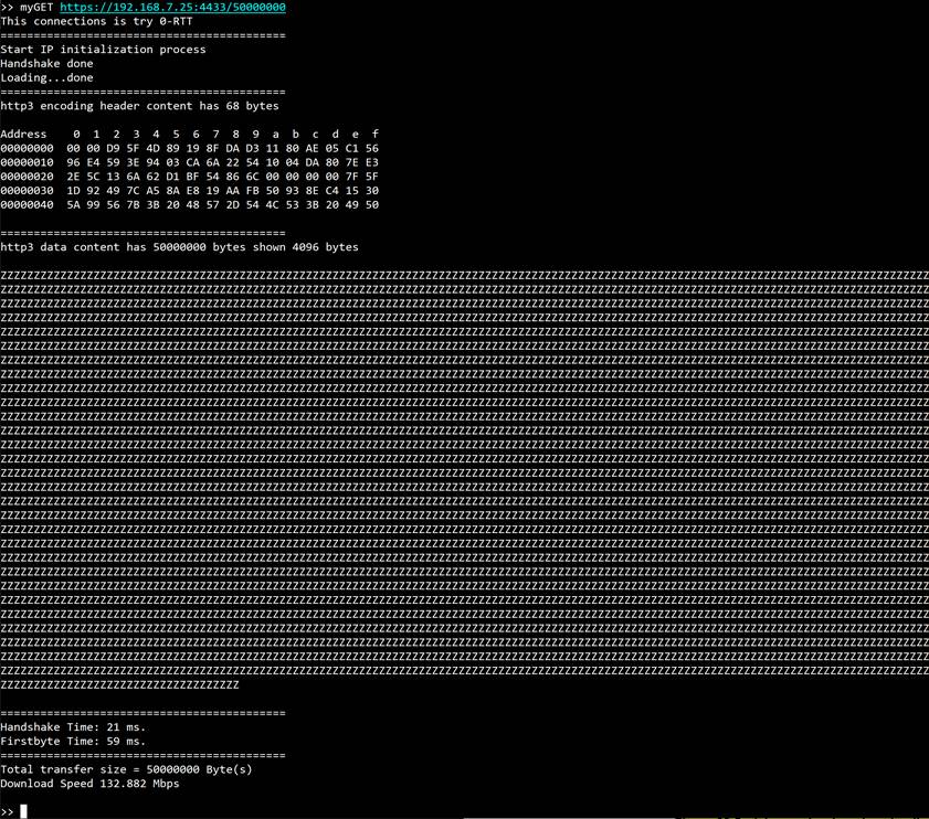
Figure 32 Serial console when downloading large data
For testing with general server, QUIC10GCdemo will display the received data on the serial console, as shown in Figure 33.
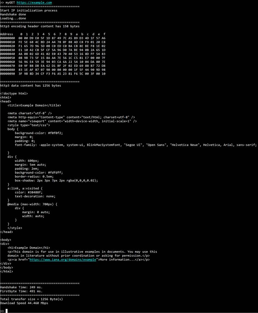
Figure 33 Serial console when downloading webpage
7.10 POST method
command> myECHO protocol://ip:port/echo length
This command simulates the POST method of HTTP/3 to upload data to the aioquic server. The URL structure for running the POST method is similar to the GET method with the exception that the transfer length is replaced by a string of “echo”. Users can instead specify the length of the uploading data, which is an 8-bit counting pattern, in another option. After the upload is completed, the aioquic server will return what it has received. This allows the users to verify the received data from the aioquic server. By enabling the verification feature, it monitors whether the received data matches the expected pattern or not, and after verifying it, the data content, transfer length, and transfer speeds are displayed, as shown in Figure 34 and Figure 35.
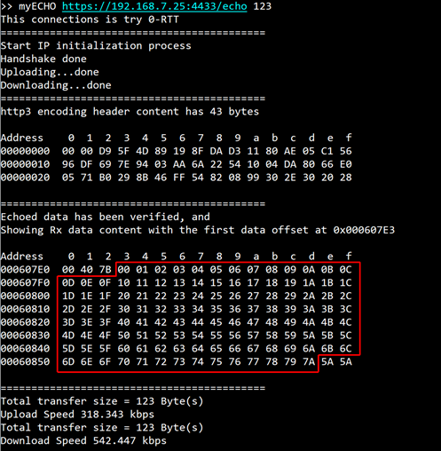
Figure 34 Serial console when uploading small data
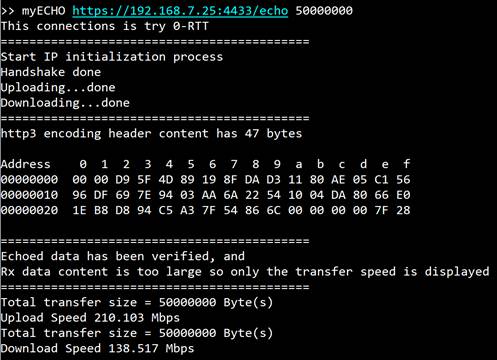
Figure 35 Serial console when uploading large data
7.11 PERF method
command> myPERF ip:port uploadlength downloadlength
This command is designed to run with the “secnetperf” example of an MsQuic server. There are three parameters required to run this command – the first option is the server’s IP address and server’s port number separated by a colon, the second is the length of the upload data, and the last one is the length of the download data.
Specifically, this application protocol is designed to have the client transferring the upload data firstly, after which the client receives the download data from the server. Similar to the POST method, the verification feature is used to monitor the received data, and the results, such as the download content, the transfer length, and the transfer speeds, are presented, as shown in Figure 36. It is also important to note that the performance of this operation depends on the network system and the resources available on the test machine.
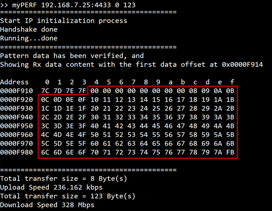
Figure 36 Serial console when downloading small data
Figure 36 is not a good example to represent the transfer performance because the operation time is too small for accurate calculation. Figure 37, however, can be used to show the transfer speeds for both upload and download because the transfer size settings are large enough.
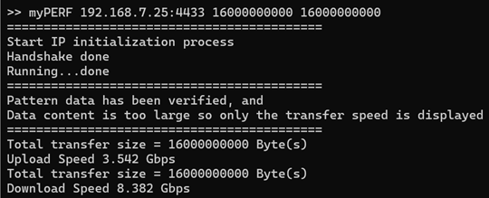
Figure 37 Serial console when downloading large data
8 Example Test Result
This test result demonstrates performance between two FPGA boards using the QUIC10GC-IP as the client and the QUIC10GS-IP as the server, ensuring no bottleneck from CPU software. The test utilizes a secure connection over the QUIC transport protocol, enabling high-speed data transfer with hardware acceleration. At the application layer, a dedicated protocol—similar to MsQuic’s ‘secnetperf’ example—is implemented to measure performance. This setup enables a fully hardware-driven QUIC communication, independent of software processing constraints.
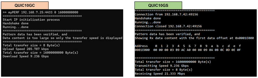
Figure 38 Client and server and console display during data transfer from server to client
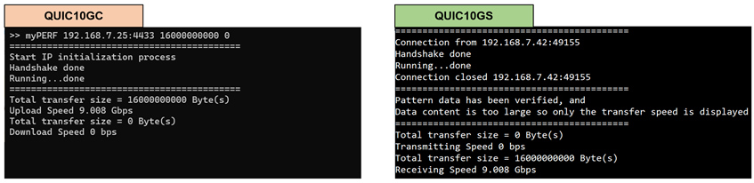
Figure 39 Client and server and console display during data transfer from client to server
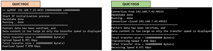
Figure 40 client and server console display during Full-Duplex data transfer
The performance test for QUIC10GC-IP on an FPGA board was conducted using QUIC10GC-IP as the QUIC client. At the application layer, a dedicated protocol—similar to MsQuic’s ‘secnetperf’ example—was implemented to measure performance. The results compare the performance of QUIC10GC-IP with MsQuic’s software as a server on a PC and QUIC10GC-IP with QUIC10GS-IP as a server on an FPGA.
When QUIC10GC-IP, acting as a hardware-based QUIC client, downloads data from MsQuic, a software-based QUIC server running on a PC, the throughput is approximately 8.3 Gbps, while the speed when QUIC10GC-IP uploads data to MsQuic reaches 3.5 Gbps. The utilization of the Intel i7 CPU is approximately 100%, as monitored by the PC’s task manager. This indicates that the client fully drives the CPU when transferring QUIC data over the network.
On the other hand, when QUIC10GC-IP downloads data from QUIC10GS-IP—an FPGA-based QUIC server—the speed is approximately 9.0 Gbps. The speed when QUIC10GC-IP uploads data to QUIC10GS-IP is also 9.0 Gbps, and when QUIC10GC-IP performs upload and download simultaneously on QUIC10GS-IP, the resulting throughput reaches 8.0 Gbps, as shown in Table 1.
Table 1 QUIC10GC-IP Performance test result
|
Client |
Download (Gbps) |
Upload (Gbps) |
Full Duplex (Gbps) |
CPU Utilization |
|
MsQuic (Software on PC) |
8.3 |
3.5 |
- |
~100% |
|
QUIC10GC-IP (on FPGA) |
9.0 |
9.0 |
8.0 |
- |
9 Revision History
|
Revision |
Date (D-M-Y) |
Description |
|
1.00 |
3-Dec-25 |
Initial version release |