Rev1.00 2-Jun-2023
4.2 SignalTap trigger condition
4.2.1 To see set length signals timing
4.2.2 To see data transfer signals timing
4.2.3 To see hash result signals timing
5.1 Demo software interface description
5.2 Hash function by input text
5.3 Speed test with 64-bit counter pattern data
This document describes the instruction to demonstrate the operation of SHA256IP on Arria10SoC development board. This demonstration uses SHA256IP demo software to communicate with development board via 1-Gb Ethernet for set length of data, send input text data, and read hash result. User is also able to use SignalTap to see the operation of provided signals in FPGA.
1 Environment Setup
To operate SHA256IP demo, please prepare following test environment.
1) FPGA development boards (Arria10SoC development board)
2) Test PC with 1-Gb Ethernet connection.
3) Micro USB cable for JTAG connection connecting between FPGA development board and PC
4) Ethernet cable (Cat5e or Cat6) for network connection between FPGA development board and PC
5) Quartus Prime for programming FPGA, installed on Test PC
6) File “SHA256IPDemoPack.zip” that included Test Application named “SHA256IP Demo”, configuration file named “SHA256IPTest_time_limited.sof” and SignalTap file named “stp1.stp”.
(To download this file, please visit our web site at www.design-gateway.com)

Figure 1‑1 SHA256IP demo (FPGA<->PC) on Arria10SoC board
2 PC Setup
Before running demo, please check the network setting on PC. Ethernet setting is shown as follows.
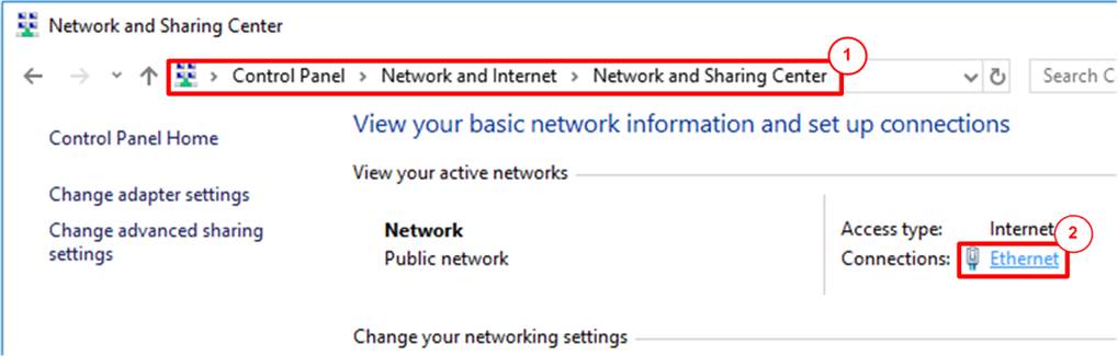
Figure 2‑1 IPv4 setting
1) Open Ethernet setting option from Control Panel -> Network and Internet -> Network and Sharing Center.
2) Click Ethernet icon which is used to connect with FPGA board.
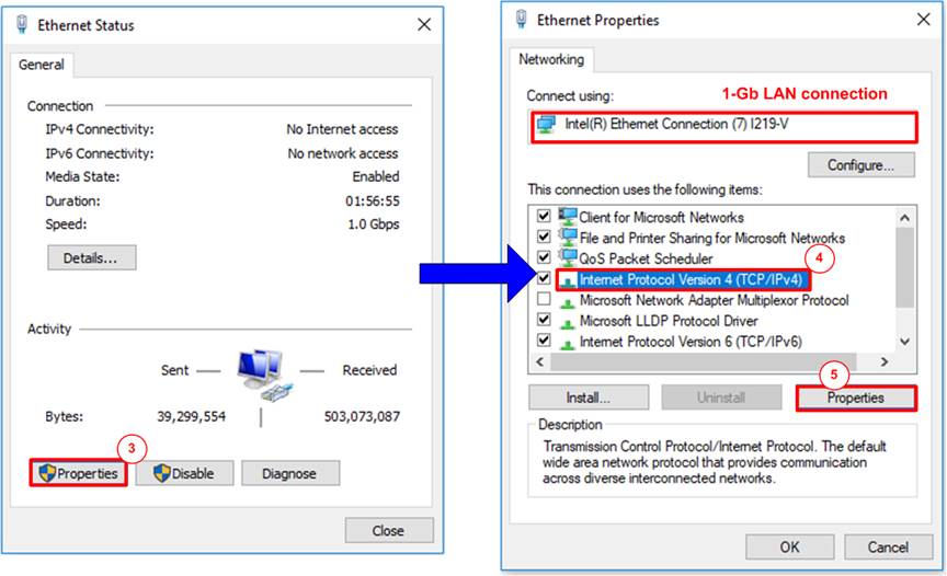
Figure 2‑2 Select IP address setting menu
3) Click Properties button in Ethernet Status window.
4) Select “TCP/IPv4”.
5) Click Properties button in Ethernet Properties window.

Figure 2‑3 Set IP address
6) Set IP address = 192.168.11.81 and Subnet mask = 255.255.255.0. After that, click OK button to confirm IP address setting.
3 FPGA board setup
1) Make sure power switch is off and connect power supply to FPGA development board.
2) Connect USB cable between FPGA board and PC via micro USB
3) Connect CAT5e/CAT6 cable between PC and Ethernet connection of FPGA board. User must use the right port when FPGA board has two 1Gb Ethernet ports.
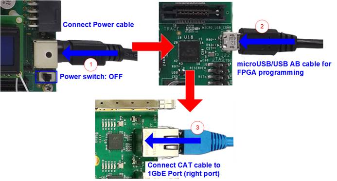
Figure 3‑1 Power, Ethernet, and micro USB cable connection
5) Open QuartusII Programmer to program FPGA through USB-1 by following step.
a) Click “Hardware Setup…” to select USB-BlasterII.
b) Click “Auto Detect” and select FPGA device. (10AS066N3).
c) Select FPGA device icon.
d) Click “Change File” button, select SOF file in pop-up window, and click “open” button
e) Check “program”
f) Click “Start” button to program FPGA.
g) And wait until Progress status is equal to 100%

Figure 3‑2 FPGA Programmer
6) When configuration is completed, Quartus will show popup message of OpenCore Plus as shown in Figure 3‑3 OpenCore Plus Status. Please do not press cancel button, because configuration in FPGA will stop running.

Figure 3‑3 OpenCore Plus Status
7) When configuration is completed, user can check status LEDs on board as Figure 3‑4
o LED#1 is always blink to show clock is working.
o LED#2 is rstB signal. This LED#2 is related to hardware reset switch “S10”.
o LED#3 is “Connection on” status of TOE1G-IP. This LED is on when software open connection to board.
o LED#4 is “Ready” status of TOE1G-IP. This LED is on when ethernet connection between PC and board is ready.

Figure 3‑4 LEDs status on board
4 SignalTap setup
This designed block diagram of this demo is shown as in Figure 4‑1. SignalTap is prepared to see all control signals between SHA256IP and user logics design.

Figure 4‑1 Demo environment block diagram
4.1 SignalTap operations
Step to use SignalTap II Logic Analyzer is as follows.
a) Click File -> Open …, then select file type to SignalTap II Logic Analyzer Files (*.stp)
b) Select “stp1.stp”, then click Open button as shown in Figure 4‑2
c) As in Figure 4‑3, connect FPGA board by select Hardware to USB-BlasterII.
d) Setup trigger condition to specify signals behavior. Sample of trigger condition and result is shown as in topic 4.2
e) Click “Run Analysis” button, wait to capture signals from SHA256IP.
f) The result will be shown, when do SignalTap detect signals same as trigger condition.

Figure 4‑2 Open file “stp1.stp”

Figure 4‑3 SignalTap II Logic Analyzer
4.2 SignalTap trigger condition
On demo running, user is able to use SignalTap to setup trigger condition and check the signal waveform after trigger is detected. The prepared SignalTap signals are separated to 3 parts as (1) Set length, (2) Data transfer and (3) Hash result, respectively.
4.2.1 To see set length signals timing
Figure 4‑4 show trigger condition and Figure 4‑5 show sample result from SignalTap when user press hash button in topic 5.2 or 5.3.

Figure 4‑4 Trigger setup for set length signals

Figure 4‑5 Sample result for set length signals
4.2.2 To see data transfer signals timing
Figure 4‑6 show trigger condition and Figure 4‑7 show sample result from SignalTap user press hash button in topic 5.2 or 5.3.

Figure 4‑6 Trigger setup for data transfer

Figure 4‑7 Sample result for data transfer signals
4.2.3 To see hash result signals timing
Figure 4‑8 show trigger condition and Figure 4‑9 show sample result from SignalTap when user press hash button in topic 5.2 or 5.3.

Figure 4‑8 Trigger setup for input key and searching result

Figure 4‑9 Sample result for input key and searching result
5 SHA256IP demo software
SHA256IP demo software is used for show hash function that compute by SHA256IP in A10SoC board via 1-Gb Ethernet connection.
5.1 Demo software interface description

Figure 5‑1 Software interface
Figure 5‑1 shows SHA256IP demo software and the description is shown as below.
a) Connect button is used for open connection to A10SoC board via 1Gb-Ethernet.
b) This section is hash functional test by input text.
c) This section is speed test function with fixed data pattern by 64-bit counter pattern.
5.2 Hash function by input text
User can input text data and press hash button, then software will transfer input text to SHA256IP and get the hash result back to show in “length : hash” text box. Figure 5‑2 shows example of hash function by input text.

Figure 5‑2 Example of hash function by input text
5.3 Speed test with 64-bit counter pattern data
User can input data size (bytes unit), and press “Speed test with 64-bit Counter” button. Then software will show pattern of data in counter pattern text box and send command to A10SoC board to start generate test pattern data send to SHA256IP. After hash function is finished, software will get the result hash value and show in “length : hash” text box. Then software will popup message to show time of hash function operation. Figure 5‑3 shows example of speed test with 64-bit counter pattern data.

Figure 5‑3 Example of speed test with 64-bit
counter pattern data
6 Revision History
|
Revision |
Date |
Description |
|
1.00 |
26-Jan-2021 |
Initial version release |