3 Hardware Operation Sequences
3.3 Hash with Message from User
3.4 Hash Performance Test Mode with Constant Input
4.2 Hash performance test mode
1 Introduction
This document provides a detailed overview of the SHA3-IP reference design, targeted at the AMD Kria KR260 Robotics Starter Kit. In this reference design, the SHA3-IP core is integrated with custom user-space interface registers under the UserReg module. The processor system (PS) running embedded firmware interacts with the hardware core over an AXI4-Lite interface. Through a serial console connection, users can select SHA-3/SHAKE algorithms, load custom input messages, perform high-speed hardware-driven performance tests, and monitor hash results and execution times.
2 Hardware Overview
As shown in Figure 1, the reference design is split into two clock domains to ensure reliable operation. The CpuClk domain handles high-speed processor bus transactions (AXI4-Lite), while the UserClk domain operates at the clock speed of the cryptographic engine.
The SHA3Test module contains the AXI-to-Register synchronizer (AsyncAXIReg) and the user register mapping file (UserReg.v). These blocks cross the clock boundary safely using double-register handshake logic and convert standard AXI4-Lite read/write transactions into basic clock-domain-synchronized 32-bit registers.
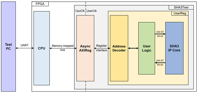
Figure 1 SHA3-IP reference design block diagram
2.1 AsyncAXIReg
This module is designed to convert the signal interface of a memory-mapped bus into a register interface. Also, it enables two clock domains, CpuClk and UserClk domain, to communicate.
To write register, RegWrEn is asserted to ‘1’ with the valid signal of RegAddr (Register address in 32-bit unit), RegWrData (write data of the register), and RegWrByteEn (the byte enable of this access: bit[0] is used for RegWrData[7:0], bit[1] is used for RegWrData[15:8], …, and bit[3] is used for RegWrData[31:24]).
To read register, AsyncAXIReg asserts RegRdReq=‘1’ with the valid value of RegAddr (the register address in 32-bit unit). After that, the module waits until RegRdValid is asserted to ‘1’ to get the read data through RegRdData signal at the same clock.
2.2 UserReg
For register file, UserReg is designed to write/read registers, control and check status of the SHA3-IP corresponding with write register access or read register request from AsyncAXIReg module. Memory map inside UserReg module is shown in Table 1. Timing diagram of register interface is shown in Figure 2.
Table 1 Register Map Definition of SHA3-IP
|
Offset Address |
Register Name |
Access |
Width (bits) |
Description |
|
Identification |
||||
|
0x0000 |
SHA3_VERSION_REG |
Rd |
32 |
SHA3-IP version |
|
Configuration Registers |
||||
|
0x0010 |
USER_OUTLEN_REG |
Wr/Rd |
32 |
Output hash size in bytes. Used for SHAKE128 and SHAKE256 algorithms. |
|
0x0014 |
USER_BYTE_EN_REG |
Rd |
8 |
Active-high byte-enable mask for the current input word. |
|
0x0020 |
USER_CMD_REG |
Wr/Rd |
3 |
Algorithm select: 000=SHA3-224, 001=SHA3-256, 010=SHA3-384, 011=SHA3-512, 100=SHAKE128, 101=SHAKE256. |
|
0x0024 |
USER_READY_REG |
Rd |
1 |
SHA3 IP ready flag. 1 = core ready to accept new data word. |
|
Data Input Registers |
||||
|
0x0028 |
USER_DATAIN_LO_REG |
Wr/Rd |
32 |
Lower 32 bits of 64-bit input data. |
|
0x002C |
USER_DATAIN_HI_REG |
Wr/Rd |
32 |
Upper 32 bits of 64-bit input data. Writing this register triggers data absorption into the SHA3 core. |
|
0x0050 |
USER_DATALEN_REG |
Wr/Rd |
32 |
Input message length in bytes. Auto-decrements by 8 for every 64-bit word processed. |
|
0x0130 |
USER_DATAIN2_LO_REG |
Wr/Rd |
32 |
Alternate lower 32-bit input data. |
|
0x0134 |
USER_DATAIN2_HI_REG |
Wr/Rd |
32 |
Alternate upper 32-bit input data (does not trigger valid). |
|
Streamed Hash Output Registers |
||||
|
0x0034 |
USER_STM_READY_REG |
Wr/Rd |
1 |
Write 1 to StmOutReady. |
|
0x0040 |
USER_STM_FLAGS_REG |
Rd |
10 |
[7:0]: StmDataByteEn. [8]: StmDataLast. [9]: StmDataValid. |
|
0x0044 |
USER_STM_LAST_REG |
Wr/Rd |
1 |
StmDataLast latch. Write 0 to clear. |
|
0x0120 |
USER_HASH_STM_REG(0) |
Rd |
32 |
Lower 32 bits of the streamed hash output. |
|
0x0124 |
USER_HASH_STM_REG(1) |
Rd |
32 |
Upper 32 bits of the streamed hash output. |
|
Parallel / Latched Hash Output Registers |
||||
|
0x0060 |
USER_HASHVALID_REG |
Wr/Rd |
1 |
Parallel hash output valid flag. Write 0 to clear. |
|
0x0070 - 0x0114 |
USER_HASH_LATCH_REG(0-41) |
Rd |
32 each |
42 registers holding
latched parallel hash output (up to 1344 bits). |
|
Test Mode Register |
||||
|
0x0128 |
USER_TESTMODE_REG |
Wr/Rd |
2 |
[0]: Flag to enable hash with constant pattern (rTestModeConsWrEn). |
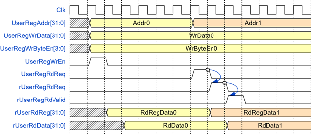
Figure 2 Register interface timing diagram
3 Hardware Operation Sequences
This section describes the register-level operations required to drive the SHA3-IP from firmware. The CPU interacts with the IP through memory-mapped registers defined in UserReg. The following subsections cover parameter setup, data input, and hash output retrieval.
3.1 Operation Overview
SHA3-IP supporting four fixed-length variants (SHA3-224, SHA3-256, SHA3-384, SHA3-512) and two extendable-output functions (SHAKE128, SHAKE256). Data is written in 64-bit words via USER_DATAIN_LO_REG and USER_DATAIN_HI_REG. The IP signals readiness through USER_READY_REG and signals completion through USER_HASHVALID_REG. Hash output can be read from either the latched registers or consumed from the streaming interface.
3.2 Parameter Setting
Before starting a hash operation, the user must configure three parameters: the SHA3 algorithm command, the input message length, and, for SHAKE modes, the desired output length.
The SHA3 algorithm is selected by writing the command value to USER_CMD_REG(rCmd[2:0]), which maps to SHA3Cmd inside the IP.
The input message length in bytes is configured by writing to USER_DATALEN_REG. The maximum supported input length is 2³² − 1 bytes (approximately 4 GB). The byte-enable signal wByteEn is automatically derived from the lower three bits of rDataLen to indicate the number of valid bytes in the final 8-byte word. When rDataLen is an exact multiple of 8, all eight bytes of the last word are valid (wByteEn = 0xFF).
For SHAKE128 and SHAKE256, the user must also write the desired output length in bytes to USER_OUTLEN_REG. For fixed-length SHA3 variants, the output length is determined by the algorithm and USER_OUTLEN_REG is ignored.
Before start the hash operation, the user must also clear the status registers by writing 0 to both USER_HASHVALID_REG and USER_STM_LAST_REG. This ensures that any flags asserted from a previous operation are de-asserted before the new hash begins, preventing false status detection during the current transaction.
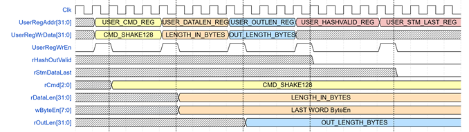
Figure 3 Timing diagram of parameter setting process
3.3 Hash with Message from User
To hash a message, the user start writing data to USER_DATAIN_LO_REG followed by USER_DATAIN_HI_REG. Each pair of writes supplies one 64-bit input word. Writing to USER_DATAIN_HI_REG triggers the IP to assert rDataInValid, which presents the 64-bit word to SHA3-IP.
The IP automatically asserts rDataInLast and sets wByteEn for the last word when rDataLen reaches 8 or fewer remaining bytes. As shown in Figure 4.
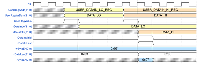
Figure 4 Timing diagram of Hash with Message from User process
3.4 Hash Performance Test Mode with Constant Input
To hash a large constant-fill message without the CPU manually writing every word, the user can enable hardware constant-streaming mode. The 64-bit constant(0x00) is first written to USER_DATAIN2_LO_REG and USER_DATAIN2_HI_REG. Both USER_HASHVALID_REG and USER_STM_LAST_REG are then cleared to zero before writing 0x03 to USER_TESTMODE_REG, which simultaneously asserts rTestModeConsWrEn and rTestModeStmReady.
Once active, the hardware automatically asserts rDataInValid and drives the constant value into the core until rDataLen bytes have been consumed. The CPU does not need to write any further data words; the IP manages all remaining absorb cycles autonomously.
The user then polls USER_HASHVALID_REG bit 0 until the first output word becomes valid. For modes that produce extended output, the hardware streams the output words internally; the CPU polls USER_STM_LAST_REG bit 0 to confirm all output words have been produced before reading the final result from the hash latch registers. After the operation completes, USER_STM_LAST_REG is cleared and USER_TESTMODE_REG is written to 0x00.
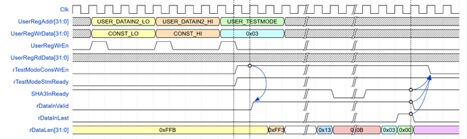
Figure 5 Timing diagram of Hash with Predefined
Constant Patterns process
3.5 Hash Output
SHA3-IP provides two output paths: a parallel output and a streaming output.
For the latched parallel output, rHashOutLatch[1343:0] captures the hash output each time ParallelOutValid is asserted. In this reference design, USER_HASH_LATCH_REG is used only to display the most recent hash block. The valid byte range within the latch depends on the selected algorithm and, for SHAKE, on the output length.
As shown in Figure 6, for SHA3-256, the 32-byte digest occupies USER_HASH_LATCH_REG(41) through USER_HASH_LATCH_REG(34)
For the streaming output, the IP presents hash data 64 bits at a time through the streaming interface. The user polls USER_STM_FLAGS_REG, which encodes StmDataValid in bit 9, StmDataLast in bit 8, and the 8-bit byte-enable mask StmDataByteEn in bits [7:0]. When bit 9 is set, the user reads USER_HASH_STM_REG(0) and USER_HASH_STM_REG(1) to obtain the current 64-bit output word. After reading, the user writes any value to USER_STM_READY_REG, which pulses StmOutReady high for one clock cycle to advance the stream to the next output word. This loop repeats until bit 8 (StmDataLast) is set, indicating the final output word has been delivered.
When the StmDataLast signal is asserted, the IP core latches it into rStmDataLast within USER_STM_LAST_REG. This register serves as an indicator that the streaming output has completed, allowing the user to stop waiting in performance test mode. To prepare for the next operation, the user must clear this flag by writing to the USER_STM_LAST_REG address. As shown in Figure 6, for SHA3-256 the streaming output delivers 32 bytes across four consecutive 64-bit words while StmOutReady used to control the stream output.
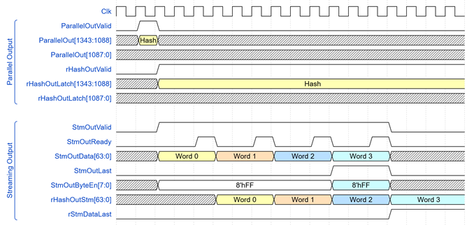
Figure 6 Timing diagram of Hash Output for SHA3-256
4 CPU Firmware Logic
After system boot-up, the CPU initializes its peripherals including UART and Timer. The supported command options are then displayed. The main function runs in an infinite loop, displaying the main menu and reading keyboard input via the serial console. The user selects each menu item by pressing the corresponding key, which calls the related function. After the function returns, the main menu is displayed again. The firmware boots with SHAKE128 selected as the default mode and an output length of 16 bytes. The details of each menu item are described in the following subsections.
4.1 Hash with Input Message
This menu is used to functionally test the SHA3-IP by generating a hash from a user-provided hexadecimal input message. The supported command options are shown on startup. The user selects each menu item by pressing the corresponding key.
The message2hash() function is called to initiate the hash-from-message process. The operational sequence is as follows:
1) If SHAKE128 or SHAKE256 is active, prompt the user to enter the desired output length in bytes.
2) Prompt the user to enter the input message as a hexadecimal string using getStr().
3) Set parameters in the SHA3-IP (output length, SHA3 command) and configure the input data length. Clear USER_STM_LAST_REG and USER_HASHVALID_REG to 0.
4) Start the timer, continue to write the input message to the SHA3-IP via wrStr().
5) Display the streaming hash output.
6) Display the last hash block from USER_HASH_LATCH_REG. For SHA3 fixed variants, the latch holds the complete digest. For SHAKE modes, only the final squeeze block is held, as earlier blocks have already been consumed through the streaming interface. This step is performed internally by show_hash_stm() via its call to show_hash() and is not a separate CPU action in the caller.
7) Display the execution time and throughput speed.
Table 2 message2hash function
|
void message2hash(unsigned int maxStr, unsigned int cmd, unsigned int d_len) |
|
|
Parameter |
unsigned int maxStr: The maximum allowed length of the hex input string in characters. unsigned int cmd: The SHA3 command type unsigned int d_len: The output digest length in bytes. Applies to SHAKE modes; fixed for SHA3 variants. |
|
Return value |
None |
|
Description |
Prompts the user for the input byte count and output length for SHAKE modes. Configures the SHA3-IP registers, streams an constant via performance test mode, and reports elapsed time and throughput. Displays the final latched hash once streaming completes. |
Table 3 wrStr function
|
void wrStr(char *str, unsigned int strLen) |
|
|
Parameter |
char *str: Pointer to the byte buffer containing the message to be written. unsigned int strLen: The total number of bytes in the buffer. |
|
Return value |
None |
|
Description |
This function writes the given byte buffer to the SHA3-IP eight bytes at a time. The lower four bytes of each 8-byte word are written to USER_DATAIN_LO_REG and the upper four bytes to USER_DATAIN_HI_REG. Before each 8-byte write, the function polls USER_READY_REG until the IP signals readiness. Writing to USER_DATAIN_HI_REG triggers the IP to latch the full 64-bit word. |
Table 4 getStr function
|
static int getStr(char *str, unsigned int *strLen) |
|
|
Parameter |
char *str: Pointer to the buffer where the input string will be stored. unsigned int *strLen: Pointer to the variable that receives the input string length. |
|
Return value |
int: Returns 0 on success, -1 if the user presses ESC to cancel. |
|
Description |
This function continuously reads characters from the UART until a newline is received. The string is stored in the provided `str` buffer and its length is updated in `strLen`. |
Table 5 show_hash_stm function
|
void show_hash_stm(unsigned int cmd, unsigned int d_len) |
|
|
Parameter |
unsigned int cmd: The SHA3 command type, used to determine the total expected output length. unsigned int d_len: The output length in bytes for SHAKE modes. |
|
Return value |
None |
|
Description |
This function reads the hash result from the streaming output interface and prints it in hexadecimal format. It polls USER_STM_FLAGS_REG for bit 9 (wStmDataValid), reads USER_HASH_STM_REG, uses the byte-enable mask from bits [7:0] to select valid bytes, then writes to USER_STM_READY_REG to advance the stream. This loop continues until bit 8 (wStmDataLast) is set. After consuming the stream, the function calls show_hash() to also display the lastest hash block. |
Table 6 show_hash function
|
void show_hash(unsigned int cmd, unsigned int d_len) |
|
|
Parameter |
unsigned int cmd: The SHA3 command type. unsigned int d_len: The output length in bytes. Used for SHAKE modes. |
|
Return value |
None |
|
Description |
This function reads the latest latched hash output from USER_HASH_LATCH_REG registers and prints the result in hexadecimal format to the UART console, and its size is reported in the label. |
4.2 Hash performance test mode
This menu is used to evaluate the computational throughput of the SHA3-IP when processing large volumes of data consisting of constant-fill constant bytes (0x00). The length2hash() function is called to initiate the process. The operational sequence is as follows:
1) If SHAKE128 or SHAKE256 is active, prompt the user to enter the desired output length in bytes.
2) Prompt the user to enter the number of input bytes to hash.
3) Set parameters in the SHA3-IP (output length, SHA3 variant command) and configure the input data length.
4) Write a single all-zero 64-bit word to USER_DATAIN2_LO_REG and USER_DATAIN2_HI_REG. Start the timer immediately after writing the constant, then activate performance test mode by writing 0x03 to USER_TESTMODE_REG (asserting rTestModeConsWrEn and rTestModeStmReady). The hardware logic automatically streams the constant pattern internally.
5) Wait for the first hash output to become valid (USER_HASHVALID_REG bit 0 set), then stop the timer.
6) Display the execution time and throughput speed.
7) Wait for the streaming output to complete, then display the latched hash output.
Table 7 length2hash function
|
void length2hash(unsigned int cmd, unsigned int d_len) |
|
|
Parameter |
unsigned int cmd: The SHA3 command type (e.g., CMD_SHA3_256, CMD_SHAKE128). unsigned int d_len: The output digest length in bytes for SHAKE modes. |
|
Return value |
None |
|
Description |
Prompts the user for the input byte count and, for SHAKE modes, the output length. Configures the SHA3-IP registers, streams an all-zero constant via performance test mode, and reports elapsed time and throughput. Displays the final latched hash once streaming completes. |
4.3 SHA3 Variant Selection
SHA3-IP supports the following algorithm variants: SHA3-224, SHA3-256, SHA3-384, SHA3-512, SHAKE128, and SHAKE256. This menu allows the user to switch between these variants for hashing messages with different output length requirements. For SHAKE128 and SHAKE256 the output length is configurable at run-time; the default output lengths at boot-up are 16 bytes for SHAKE128 and 32 bytes for SHAKE256. The default mode after system boot-up is SHAKE128.
Table 8 SHA3 Variant Selection
|
Menu Key |
SHA3 Variant(Output Length) |
|
[1] |
SHA3-224(fixed 28 bytes) |
|
[2] |
SHA3-256(fixed 32 bytes) |
|
[3] |
SHA3-384(fixed 48 bytes) |
|
[4] |
SHA3-512(fixed 64 bytes) |
|
[5] |
SHAKE128(default 16 bytes, user-configurable) |
|
[6] |
SHAKE256(default 32 bytes, user-configurable) |
5 Revision History
|
Revision |
Date (D-M-Y) |
Description |
|
1.00 |
4-Jun-26 |
Initial release document for SHA3-IP reference design on Kria KR260. |