TLS10GC-IP Reference Design
2.7 Xilinx Transceiver (PMA for 10GBASE-R)
3.6 Show certificate information
3.7 Send HTTP GET request to server
3.7.2 Download data in video folder
3.7.3 Handle general GET request
1 Introduction
This document describes the details of TLS 1.3 Client 10Gbps IP Core (TLS10GC-IP) reference design. In this reference design, TLS10GC-IP is used to establish a secure connection using the Transport Layer Security protocol version 1.3 over TCP by handling TLS1.3 handshake, encrypting and decrypting data transferred between the client and the server. Users can set network parameters for TOE10GLL-IP, download and upload payloads to the server by inputting supported command via the serial console. Further details regarding the hardware design and CPU firmware are provided below.
2 Hardware
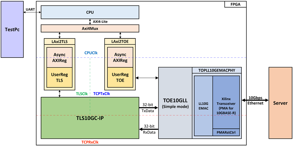
Figure 1 TLS10GC-IP reference design block diagram
In this test environment, CPU system is designed to interface with FPGA logic through AXI4 Lite bus and interface with user through serial console in test PC. CPU system communicates with hardware via memory mapping. The memory mapping is separated into two regions: TOE10GLL-IP and TLS10GC-IP. The AXI4-Lite interfaces are implemented using LAxi2TLS (for TLS10GC-IP) and LAxi2TOE (for TOE10GLL-IP), as shown in Figure 1.
The user interface of the TLS10GC-IP connects to UserRegTLS within the LAxi2RegTLS module to control and monitor the operation of TLS10GC-IP. UserRegTLS interfaces with the CPU through AsyncAXIReg using a register interface, with the CPU connecting to AsyncAXIReg via an AXI4-Lite interface.
The user interface of the TOE10GLL-IP connects to UserRegTOE within the LAxi2RegTOE module to control and monitor the operation of TOE10GLL-IP. UserRegTOE interfaces with the CPU through AsyncAXIReg. The TOE10GLL-IP is also linked to a 10G Ethernet MAC controller (LL10GEMAC-IP) through a 32-bit AXI4 Stream interface (AXI4-ST). The LL10GEMAC-IP implements the Ethernet MAC layer and the PCS layer with low latency.
This design includes five clock domains:
1) CPUClk: Used for CPU communication via the AXI4-Lite/AXI4 bus.
2) UserHClk: Used as the high-frequency clock domain for TLS10GC-IP.
3) UserLClk: Used as low frequency clock domain by TLS10GC-IP.
4) TCPTxClk: Synchronized with the Tx EMAC interface and the Tx user data interface.
5) TCPRxClk: Synchronized with the Rx EMAC interface and the Rx user data interface.
Details of each module are provided below.
2.1 AsyncAxiReg
This module is designed to convert the signal interface of AXI4-Lite to be register interface. Also, it enables two clock domains to communicate.
To write register, RegWrEn is asserted to ‘1’ with the valid signal of RegAddr (Register address in 32-bit unit), RegWrData (write data of the register), and RegWrByteEn (the byte enable of this access: bit[0] is write enable for RegWrData[7:0], bit[1] is used for RegWrData[15:8], …, and bit[3] is used for RegWrData[31:24]).
To read register, AsyncAxiReg asserts RegRdReq=’1’ with the valid value of RegAddr (the register address in 32-bit unit). After that, the module waits until RegRdValid is asserted to ‘1’ to get the read data through RegRdData signal at the same clock.
2.2 LAxi2TLS
LAxi2TLS module is connected to CPU through AXI4-Lite bus. The hardware registers for TLS10GC-IP are mapped to CPU memory address, as shown in Table 1. The control and status registers for CPU access are designed within LAxi2TLS.
LAxi2TLS consists of AsyncAxiReg and UserRegTLS. AsyncAxiReg is designed to convert the AXI4-Lite signals into a simple register interface with 32-bit data bus size (similar to AXI4-Lite data bus size).
UserRegTLS is connected to TLS10GC-IP to control, monitor and prepare data for TLS10GC-IP operation. UserRegTLS consists of register file, a dual port ram for storing certificate information (CertRam), a data pattern generator (UserDataGen) and a data pattern verification (UserDataVer), as shown in Figure 2.
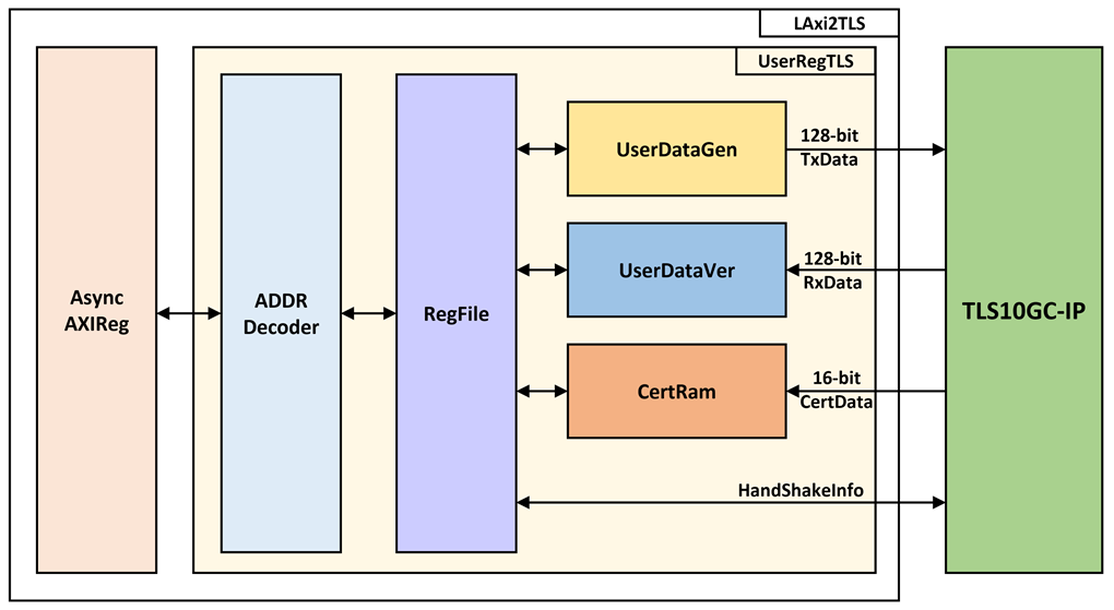
Figure 2 UserReg block diagram
Register file
For register file, UserRegTLS is designed to read/write registers, control and check alert of TLS10GC-IP corresponding with write register access or read register request from AsyncAvlReg module. The memory map inside UserRegTLS module is shown in Table 1. The timing diagram of register interface is shown in Figure 3.
Table 1 Register map Definition of TLS10GC-IP
|
Register Name |
Description |
|
|
TLS_RSTB_REG |
Wr[0]: Reset signal active low (TLSRstB). |
|
|
0x00004 |
TLS_BUSY_REG |
Rd[2]: Busy status for bypass operation (TLSBypassBusy). Rd[1]: Busy status for handshake operation (TLSHandshakeBusy). Rd[0]: Busy status for data transfer operation (TLSTrnsBusy). |
|
0x00008 |
TLS_ALERT_REG |
Rd[15:0]: Alert code from TLS10GC-IP (TLSAlertCode[15:0]). |
|
0x0000C |
TLS_TIMEOUT_REG |
Rd/Wr[15:0]: Timeout value for waiting returned packet (TLSTimeOut[15:0]). |
|
0x00010 |
TLS_MODESET_REG |
Wr[0]: Configure the mode of
the TLS10GIP (rMode). When rMode is set, rModeSet is asserted to ‘1’. |
|
0x00110 |
TLS_TX_RDPTR_REG |
Rd[13:0]: Read pointer to indicate the first byte position of TxData that IP will process (rTLSTxRdPtr). |
|
0x00114 |
TLS_TX_WRPTR_REG |
Rd/Wr[13:0]: Write pointer to indicate the position after the last TxData written (rTLSTxWrPtr). |
|
0x00118 |
TLS_RX_RDPTR_REG |
Rd/Wr[13:0]: Read pointer to indicate the first byte of RxData that user already to process (rTLSRxRdPtr). |
|
0x0011C |
TLS_RX_WRPTR_REG |
Rd[13:0]: Write pointer to indicate the position after the last RxData written (rTLSRxWrPtr). |
|
0x00120 |
USER_TX_PATT_TYPE_REG |
Wr[1:0]: Data Pattern Mode (rPattGenMode) “00”, “01”, “10” and “11” for decreasing binary, increasing binary, decreasing text, and increasing text, respectively. |
|
0x00124 |
USER_TX_PATT_LEN_REG |
Rd[31:0]: Remaining data pattern length (wPattRemainLen[31:0]) Wr[31:0]: Data pattern length (rPattGenLen[31:0]) |
|
0x00128 |
USER_RX_VERIFY_TYPE_REG |
Rd[1]: Status of Data pattern verification (wVerifyBusy) Rd[0]: Validity status (wVerifyInvalid) ‘0’ for indicating that received data is matched with data pattern, ‘1’ for indicating that received data is matched with data pattern Wr[1:0]: Verify Pattern Mode (rVerifyMode) “00”, “01”, “10” and “11” for decreasing binary, increasing binary, decreasing text, and increasing text, respectively. |
|
0x0012C |
USER_RX_VERIFY_LEN_REG |
Rd[31:0]: Remaining verify length (wDataRemainLen[31:0]) Wr[31:0]: Verify pattern length (rVerifyDataLen[31:0]) |
|
0x00130 |
HTTPHEADER_LEN_REG |
Wr[13:0]: Number of bytes for skipping HTTP header before verification. (rHttpHeaderLen) |
|
0x00134 |
HTTPTRAILER_LEN_REG |
Wr[13:0]: Number of bytes for skipping HTTP trailer before verification. (rHttpTrailerLen) |
|
0x00140 |
USER_RX_ACTUAL_DATA |
Rd[31:0]: Actual RxData (wActualData[127:0]) |
|
0x00150 |
USER_RX_EXP_DATA |
Rd[31:0]: Expected RxData (wExpData[127:0]) |
|
0x00200 |
CTS_REG |
Rd[31:0]: Client Traffic Secret (CTS) |
|
0x00230 |
STS_REG |
Rd[31:0]: Server Traffic Secret (STS) |
|
0x00260 |
TLS_KEYVALID_REG |
Rd[0]: Validity status for key material, key and iv (TLSKeyValid) |
|
0x00270 |
CH_RANDOM_REG |
Rd[31:0]: Random number in ClientHello message. (Random[255:0]) |
|
0x00290 |
CERT_STARTADDR_REG |
Wr[10:2]: Start address to store certificate information. (rUserRamCertAddr[10:2]) |
|
0x00294 |
CERT_READY_REG |
Rd/Wr[0]: Ready status for certificate information. (rTLSCertReady). This signal is set to 1 when the last certificate data is written to CertRam (TLSCertLast=’1’). |
|
0x003FC |
TLS_VER_REG |
Rd[31:0]: Mapped to IP version of TLS10GC-IP (version) |
|
0x04000 |
CERTRAM_BASE_ADDR |
Rd/Wr[31:0]: Certificate data in CertRam (wRdCert32) |
|
0x20000 |
RXRAM_BASE_ADDR |
Rd[31:0]: Rx data in UserRxBuffer (wRxRdData32) |
|
0x30000 |
TXRAM_BASE_ADDR |
Wr[31:0]: Tx data in UserTxBuffer |
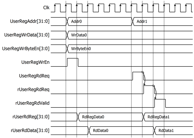
Figure 3 Register interface timing diagram
To read register, the multiplexer is designed to select the read data within each address area. UserRegAddr[13:2] is applied in each register area to select the data. Next, the address decoder uses UserRegAddr[17:14] to select the read data from each area to return to the CPU. As shown in Figure 3, the read data is valid in next two clock cycles. When UserRegRdReq is active, rUserRegRdReq is asserted to ‘1’. Then rUserRdValid is active with the valid read value of UserRegAddr.
To write register, UserRegWrEn is asserted to ‘1’ with the valid of UserRegAddr. UserRegAddr[17:14] is used to decode whether CPU accesses UserTxBuffer of TLS10GC-IP or the internal register area. The CPU can access UserTxBuffer when UserDataGen is not busy (rPattGenBusy=’0’). When the CPU accesses UserTxBuffer (UserRegAddr[17:14]=“0111”), UserRegAddr[13:4] is set to TLSTxUserAddr[13:4]. For example, when UserRegAddr[17:0]= 0x1C004 and UserRegWrEn=’1’, UserRegWrData will be filled into UserTxBuffer in TLS10GC-IP at Address 0x01. Otherwise, UserRegWrData is loaded into the internal register that matches UserRegAddr[13:2]. For example, rTLSRstBOut is loaded with UserRegWrData when UserRegAddr=0x0000.
Storing Certificate information
TLS10GC-IP is designed to provide certificate to the user for Certificate Validity Verification. In this reference design, dual port ram is used to store the certificate information. As shown in Figure 4, TLSCertData[15:0], TLSCertValid and TLSCertByteEn[1:0] can be used to write CertRam. Users can write CERT_STARTADDR_REG to set rUserRamCertAddr[12:1] as the start address to store certificate information. rUserRamCertAddr is a 13-bit counter that is incremented by 1 when TLSCertValid is asserted. rUserRamCertAddr is used as the write address for writing TLSCertData to CertRam. When TLSCertLast is asserted to ‘1’, rTLSCertReady is set to be ‘1’ to indicate that certificate data is ready.
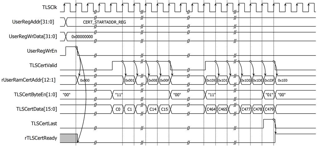
Figure 4 Example timing diagram of storing 959-byte certificate information
User Data Generator
UserDataGen is designed to generate a data pattern and write it to UserTxBuffer. There are four types of data patterns: increasing/decreasing binary pattern, increasing/decreasing text pattern. Users can set the type of data by writing to USER_TX_PATT_TYPE_REG, which is mapped to rPattGenMode signal. UserDataGen supports generating unaligned data. After the user sets the data size in byte units to rPattGenLen by writing to USER_TX_PATT_LEN_REG, the data pattern (TLSTxUserDataIn[127:0]) and TLSTxUserByteEn[15:0] are prepared corresponding to the start address.
For example, if the start address is 0x1F and user sets UserDataGen to generate 451-byte increasing text pattern, TLSTxUserDataIn[127:120] is set to 0x00 and TLSTxUserByteEn[15:0] is set to 0x8000 at the first clock cycle to write data only the highest byte at TLSTxUserAddr[13:0]= 0x10. TLSTxUserWrPtr is set to the next start address to indicate to TLS10GC-IP that there is available Tx data to transmit. At second clock cycle, every byte of data pattern is written. At the last clock cycle, only the last 2 bytes of the data pattern are written, TLSTxUserDataIn[15:0] is set to 0xC2C1 and TLSTxUserByteEn[15:0] is set to 0x0003, as shown in Figure 5.
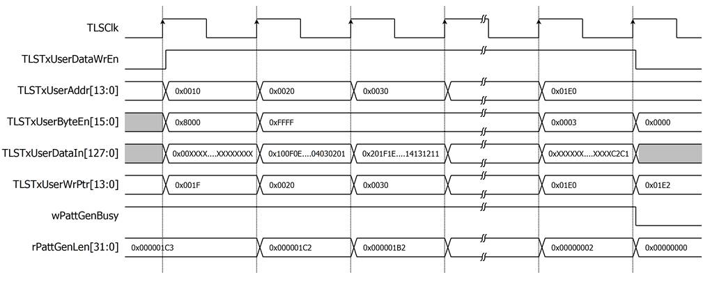
Figure 5 Example timing diagram of user data generation process
User Data Verification
UserDataVer reads data via the User Rx interface of TLS10GC-IP when there is available data in UserRxBuffer and verifies the value after starting verification (rVerifyStart is set to ‘1’). There are four types of expected data patterns: increasing/decreasing binary pattern, increasing /decreasing text pattern. Users can set the length of the HTTP header and trailer to skip before starting verification. When there is available data in UserRxBuffer, UserDataVer starts to read received data. UserDataVer supports verifying unaligned data. rExpData[127:0] and rMask[127:0] are prepared corresponding to the start address.
For example, if the start address is 0x1F, and user sets UserDataVer to verify 451-byte increasing text pattern, rExpData[127:120] is set to 0x00 and rMask[127:0] is set to 0xFF000000000000000000000000000000 at the first clock cycle to verify only the highest byte at TLSRxUserAddr[13:0]=0x10. TLSRxUserRdPtr is set to the next start address to indicate to TLS10GC-IP that UserDataVer has already processed RxData. At second clock cycle, every byte of Rx data is verified. At the last clock cycle, only the last 2 bytes of the data pattern are verified, rMask[127:0] is set to 0x0000000000000000000000000000FFFF and rExpData[15:0] is set to 0xC2C1, as shown in Figure 6.
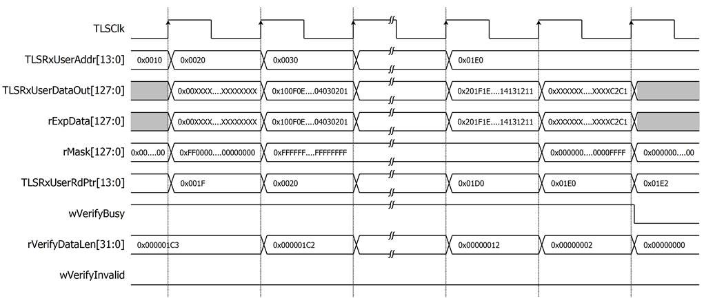
Figure 6 Example timing diagram of user data verification process
2.3 TLS10GC-IP
TLS 1.3 Client 10Gbps IP Core (TLS10GC-IP) is designed to handle TLS 1.3 handshake for client, encrypt payload before sending over the network, and decrypt application data. User can write plain TxData to UserTxBuffer or read plain RxData from UserRxBuffer via read/write ram interface with a circular buffer concept. The control interface is used to configure the operation state, handshake parameters and monitors the operation status. The TCP interface utilizes a 32-bit AXI4 stream interface. More details are described in TLS10GC-IP datasheet.
http://www.dgway.com/products/IP/TLS-IP/TLS10GCIP-datasheet-xilinx-en/
2.4 LAXi2TOE
LAxi2TOE module is connected to CPU through AXI4-Lite bus. LAxi2TOE consists of AsyncAxiReg and UserRegTOE. UserRegTOE is designed to write/read registers, control and check status of TOE10GLLIP corresponding with write register access or read register request from AsyncAvlReg module. Memory map inside UserRegTOE module is shown in Table 2
Table 2 Register map Definition of TOE10GLLIP
|
Address offset |
Register Name |
Description |
|
0x00000 |
TOE_RST_INTREG |
Wr[0]: Mapped to RstB of TOE10GLL-IP |
|
0x00004 |
TOE_OPM_INTREG |
Wr[16]: Mapped to ARPICMPEn of TOE10GLL-IP Wr[1:0]: Mapped to DstMacMode of TOE10GLL-IP |
|
0x00008 |
TOE_SML_INTREG |
Wr[31:0]: Mapped to SrcMacAddr[31:0] of TOE10GLL-IP |
|
0x0000C |
TOE_SMH_INTREG |
Wr[15:0]: Mapped to SrcMacAddr[47:32] of TOE10GLL-IP |
|
0x00010 |
TOE_DMIL_INTREG |
Wr[31:0]: Mapped to DstMacAddr[31:0] of TOE10GLL-IP |
|
0x00014 |
TOE_DMIH_INTREG |
Wr[15:0]: Mapped to DstMacAddr[47:32] of TOE10GLL-IP |
|
0x00018 |
TOE_SIP_INTREG |
Wr[31:0]: Mapped to SrcIPAddr of TOE10GLL-IP |
|
0x0001C |
TOE_DIP_INTREG |
Wr[31:0]: Mapped to DstIPAddr of TOE10GLL-IP |
|
0x00020 |
TOE_TMO_INTREG |
Wr[31:0]: Mapped to TimeOutSet of TOE10GLL-IP |
|
0x00024 |
TOE_TIC_INTREG |
Wr[0]: Set ‘1’ to clear read value of TOE_STS_INTREG[2] |
|
0x00030 |
TOE_CMD_INTREG |
Wr[1:0]: Mapped to TCPCmd of TOE10GLL-IP. |
|
0x00034 |
TOE_SPN_INTREG |
Wr[15:0]: Mapped to TCPSrcPort[15:0] of TOE10GLL-IP |
|
0x00038 |
TOE_DPN_INTREG |
Wr[15:0]: Mapped to TCPDstPort[15:0] of TOE10GLL-IP |
|
0x00040 |
TOE_VER_INTREG |
Rd[31:0]: Mapped to IP version of TOE10GLL-IP |
|
0x00044 |
TOE_STS_INTREG |
Rd[20:16]: Mapped to IPState of TOE10GLL-IP Rd[2]: TOE10GLL-IP Interrupt. Asserted to ‘1’ when IPInt is asserted to ‘1’. This flag is cleared by TOE_TIC_INTREG. Rd[1]: Mapped to TCPConnOn of TOE10GLL-IP Rd[0]: Mapped to InitFinish of TOE10GLL-IP |
|
0x00048 |
TOE_INT_INTREG |
Rd[31:0]: Mapped to IntStatus of TOE10GLL-IP |
|
0x0004C |
TOE_DMOL_INTREG |
Rd[31:0]: Mapped to DstMacAddrOut[31:0] |
|
0x00050 |
TOE_DMOH_INTREG |
Rd[15:0]: Mapped to DstMacAddrOut[47:32] |
|
0x00060 |
EMAC_VER_INTREG |
Rd[31:0]: Mapped to IP version of DG LL10GEMAC-IP |
|
0x00064 |
EMAC_STS_INTREG |
Rd[0]: Mapped to Linkup of LL10GEMAC-IP |
|
0x00070 |
HW_ACCESS_REG |
Rd/Wr[0]: Mapped to rHwAccess flag |
2.5 TOE10GLL
TOE10GLL-IP implements the TCP/IP stack and offload engine for the low latency solution. User interface has two signal groups, i.e., control signals and data signals. The IP can be configured to run in two modes, i.e., Cut-through mode for low-latency application and Simple mode for simple user interface. This reference design shows the usage in Simple mode. More details are described in datasheet.
https://dgway.com/products/IP/Lowlatency-IP/dg_toe10gllip_data_sheet_xilinx_en/
2.6 LL10GEMAC
The IP core by Design Gateway implements low-latency EMAC and PCS logic for 10Gb Ethernet (BASE-R) standard. The user interface is 32-bit AXI4-stream bus. Please see more details from LL10GEMAC datasheet on our website.
https://dgway.com/products/IP/Lowlatency-IP/dg_ll10gemacip_data_sheet_xilinx_en/
2.7 Xilinx Transceiver (PMA for 10GBASE-R)
PMA IP core for 10Gb Ethernet (BASE-R) can be generated by using Vivado IP catalog. In FPGA Transceivers Wizard, the user uses the following settings.
· Transceiver configuration preset : GT-10GBASE-R
· Encoding/Decoding : Raw
· Transmitter Buffer : Bypass
· Receiver Buffer : Bypass
· User/Internal data width : 32
The example of Transceiver wizard in Ultrascale model is described in the following link.
https://www.xilinx.com/products/intellectual-property/ultrascale_transceivers_wizard.html
2.8 PMARstCtrl
When the buffer inside Xilinx Transceiver is bypassed, the user logic must control reset signal of Tx and Rx buffer. The module is designed by state machine to run following step.
1) Assert Tx reset of the transceiver to ‘1’ for one cycle.
2) Wait until Tx reset done, output from the transceiver, is asserted to ‘1’.
3) Finish Tx reset sequence and de-assert Tx reset to allow the user logic beginning Tx operation.
4) Assert Rx reset to the transceiver.
5) Wait until Rx reset done is asserted to ‘1’.
6) Finish Rx reset sequence and de-assert Rx reset to allow the user logic beginning Rx operation.
3 CPU Firmware
After system boot-up, CPU initializes its peripherals such as UART and Timer. Then the supported command usage is displayed. The main function runs in an infinite loop to receive line command input from the user. Users can set the IP address, port number and MAC address of the FPGA board, show key materials, show certificate information, download, and upload data using the supported commands. More details of the sequence in each command are described as follows.
3.1 Set FPGA IP address
command> setip ddd.ddd.ddd.ddd[/dd]
All network parameters are configured for the TOE10GLL-IP. Users can set the IP address for TOE10GLL-IP by entering setip followed by the desired IP address in dotted-decimal format. Optionally, the subnet mask can be specified using CIDR notation (e.g., /24). If the CIDR suffix is omitted, a current value is retained. The setip function updates the IP address stored in the src_ip_set array. This array will be written to the register mapped to SrcIPAddr, which defines the FPGA’s IP address. If the subnet mask is provided, the subnet_mask_set value is also updated accordingly. After configuration, the TOE10GLL-IP is reinitialized using the current network parameter settings. The default FPGA’s IP address is 192.168.7.84/24. The setip function is described in Table 3.
Table 3 setip function
|
int setip(unsigned char * ipstr, unsigned char *ip_set) |
|
|
Parameter |
ipstr: ip address as string input from user ip_set: array stored IP address |
|
Return value |
0: Valid input, -1: Invalid input |
|
Description |
This function receives the IP Address as string inputs and updates the ip_set array. |
3.2 Set FPGA port number
command> setport ddddd
Users can set port number to TOE10GLL-IP by inputting setport followed by the static port number of the FPGA in decimal format or “dynamic”, “d” or “-d” to set the port number to be dynamic. The setport function is called to change the port number value in src_port_set array. This array will be written to the register mapped to TCPSrcPort to set the FPGA’s port number. Dynamic ports are in the range 49152 to 65535. If port number is set to be dynamic, the port number will be automatically increased by 1 before establishing a new connection. If the port number is set as a static port number and the user does not set the new port number value, the FPGA’s port number will not be changed. The setport function is described in Table 4.
Table 4 setport function
|
int setport(unsigned char *portstr, unsigned char *port_set) |
|
|
Parameter |
portstr: port number as string input from user port_set: array stored port number |
|
Return value |
0: Valid input, -1: Invalid input |
|
Description |
This function receives port number as string input and set value of port_set array. |
3.3 Set Gateway IP address
command> setgatewayip ddd.ddd.ddd.ddd
Users can set IP address for gateway by inputting setgatewayip followed by desired IP address in dotted-decimal format. The setip function is called to change the gateway’s IP address value in gateway_ip_set array. When connecting to destination in a different subnet, TOE10GLL-IP uses gateway’s IP address value as destination’s IP address to send ARP request packet and get the MAC address of gateway. This gateway’s MAC address is used to connect to the target with fixed mac mode of TOE10GLL-IP. The default gateway’s IP address is 192.168.7.2.
3.4 Set FPGA MAC address
command> setmac hh-hh-hh-hh-hh-hh
Users can set MAC address to TOE10GLLIP by inputting setmac followed by the FPGA’s MAC address in hexadecimal format. The setmac function is called to change the MAC address value in mac_set array. This array will be written to the register mapped to SrcMacAddr to set the FPGA’s MAC address. The default FPGA’s MAC address is 80-01-02-03-04-05. The setmac function is described in Table 5.
Table 5 setmac function
|
int setmac(unsigned char *macstr) |
|
|
Parameter |
macstr: MAC address as string input from user |
|
Return value |
0: Valid input, -1: Invalid input |
|
Description |
This function receives MAC Address as string input and set value of mac_set array. |
3.5 Show key materials
command> showkey <1: enable, 0: disable>
To change showkey mode, users can input showkey <1: enable, 0: disable> to modify a global variable, showTrafficSecret. If showTrafficSecret is set to ‘1’, traffic tickets will be displayed on the serial console after the handshake process is completed. Users can use the TLS traffic ticket as a (Pre)-Master-Secret log file for Wireshark* to decrypt transferred data over the current connection.
*Wireshark, a network packet analyzer tool used for network troubleshooting, analysis, and security purposes.
3.6 Show certificate information
command> showcert <1: enable, 0: disable>
To change showcert mode, users can input showcert <1: enable, 0: disable> to modify a global variable, showCertificate. If showCertificate is set to ‘1’, certificate information will be displayed on the serial console after the certificate is ready during the handshake phase. Users can use certificate information for further certificate validity verification.
3.7 Send HTTP GET request to server
command> myGET https://hostname[:port]/urlpath
Where hostname represents the server’s domain name or IP address in dot-decimal notation
port represents the server’s port number
urlpath represents the path to the desired resource on the server
This command simulates the HTTP GET method to request a resource from the server. The myGET function is called to extract the server’s IP address and the server’s port number.
If the user specifies a domain name as the hostname and it matches an existing hostname-to-IP mapping, the corresponding IP address from the table is used. If no match is found, the function prompts the user to manually enter the IP address. This IP address is then used as the network parameter and saved into the hostname-to-IP mapping for future use. If the user does not specify a port number, a default value “443” is used. The function then initializes network parameters, configures registers for data verification and monitors status. The sequence of the myGET function is as follows.
1) Parses the input URL and sets the corresponding network parameters.
2) Constructs an HTTP GET request using the provided urlpath.
3) Opens a connection and waits for the handshake process is complete.
4) Writes the HTTP GET request to UserTxRam and updates TLSTxUserWrPtr by writing TLS_TX_WRPTR_REG.
5) Executes behavior based on the format of the urlpath, as described in the sub-sections as follows.
3.7.1 Download data pattern
urlpath> download/pattern/length
Where pattern represents the data pattern: b0 for decreasing binary, b1 for increasing binary,
t0 for decreasing text, t1 for increasing text
length represents the data length in byte
In this case, the myGET function simulates an HTTP GET request to download a specific data pattern from the server and performs the following additional steps.
1) Sets HTTP header length (HTTPHEADER_LEN_REG), trailer length (HTTPTRAILER_LEN_REG), data pattern type (USER_RX_VERIFY_TYPE_REG) and data length (USER_RX_VERIFY_LEN_REG) for data verification.
2) Monitors the verification status via TLS_VERIFY_INVALID and the remaining data pattern length via USER_RX_VERIFY_LEN_REG.
3) Until the reception of data is complete, the transfer speed is computed and displayed on the serial console. If the received data length is less than 16 kB, the received data also be shown on the serial console.
3.7.2 Download data in video folder
urlpath> download/video/filename
Where filename represents the file name in video folder
For file downloads, the myGET function downloads existing files from the video folder via an HTTP GET request. The function reads the received data in HTTP response format and monitors the write and read pointers of TLS10GC-IP to determine the available data in the UserRxBuffer.
3.7.3 Handle general GET request
If urlpath does NOT match the formats in sections 3.7.1 or 3.7.2, the myGET function will display the received data on the serial console until either an alert is received from the server or a timeout occurs.
Table 6 myGET function
|
int myGET(unsigned char *urlstr) |
|
|
Parameter |
urlstr: URL as string input from user |
|
Return value |
0: Valid input, -1: Invalid input |
|
Description |
This function receives URL as string input and validates URL. If URL is valid, HTTP GET command will be sent and display receiving result. |
3.8 Upload data pattern
command> myPOST https://ip:port/upload/pattern/length
Where ip represents server’s ip address in dot-decimal notation
port represents server’s port number
pattern represents the data pattern
length represents the data length in byte
This command simulates the HTTP POST method to upload a data pattern to the server. myPOST function is called to extract the server’s IP address and the server’s port number, initialize network parameters, set registers to start data generator and monitor status. The sequence of the myPOST function is as follows.
1) Parses the input URL and sets the corresponding network parameters.
2) Constructs an HTTP POST request using the provided URL.
3) Opens a connection and waits for the handshake process is complete.
4) Writes the HTTP POST request to UserTxRam and updates TLSTxUserWrPtr by writing TLS_TX_WRPTR_REG.
5) Sets the data pattern type in USER_TX_PATT_TYPE_REG and the data length to USER_TX_PATT_LEN_REG.
6) Monitors remaining data pattern length (USER_TX_PATT_LEN_REG).
7) Until the remaining data pattern length is zero, (indicating all data has been sent), or the connection is closed. The transfer speed is computed and displayed on the serial console.
Table 7 myPOST function
|
int myPOST(unsigned char *urlstr) |
|
|
Parameter |
urlstr: URL as string input from user |
|
Return value |
0: Valid input, -1: Invalid input |
|
Description |
This function receives URL string input by user, validate and construct HTTP POST command to send before transferring data to server. Monitor UserDataGen status and number of transferred data to show transfer speed. |
3.9 Full duplex test
command> myFullduplex https://ip:port/fullduplex/pattern/length
Where ip represents server’s ip address in dot-decimal notation
port represents server’s port number
pattern represents the data pattern
length represents the data length in byte
This command is used to transfer data between the client and the server in full duplex mode. It simulates POST method of HTTP with the fullduplex URL that requests a data pattern from the server and also uploads the data pattern to the server. myFullduplex function is called to extract the server’s IP address and the server’s port number, initialize network parameters, set registers to start data generator/verification and monitor status. The sequence of the myFullduplex function is as follows.
1) Parses the input URL and sets the corresponding network parameters.
2) Constructs an HTTP POST request using the provided URL.
3) Opens a connection and waits for the handshake process is complete.
4) Writes the POST request to UserTxRam and updates TLSTxUserWrPtr by writing to TLS_TX_WRPTR_REG.
5) Set the data pattern type to USER_TX_PATT_TYPE_REG and the data length to USER_TX_PATT_LEN_REG for Tx operation.
6) Set the HTTP header length to HTTPHEADER_LEN_REG, the trailer length to HTTPTRAILER_LEN_REG, set the data pattern type to USER_RX_VERIFY_TYPE_REG and the data length to USER_RX_VERIFY_LEN_REG to verify data pattern for Rx operation.
7) Monitor Tx operation status by considering the remaining data pattern length (USER_TX_PATT_LEN_REG) and TOE10GLL busy status (TOE_STS_INTREG) and Rx operation status by considering verification status (TLS_VERIFY_INVALID) and remaining verify pattern length (USER_RX_VERIFY_LEN_REG).
8) Until the transmission and the reception of data are complete, or the connection is closed. The transfer speed is computed and displayed on the serial console.
Table 8 myFullduplex function
|
int myFullduplex(unsigned char *urlstr) |
|
|
Parameter |
urlstr: URL as string input from user |
|
Return value |
0: Valid input, -1: Invalid input |
|
Description |
This function receives URL string input by user, validate and construct HTTP POST command to send data pattern and request the same data from server. Monitor Tx/Rx operation status and number of data and show transfer speed. |
4 Revision History
|
Revision |
Date (D-M-Y) |
Description |
|
1.05 |
9-Oct-25 |
Update setip command to support CIDR notation |
|
1.04 |
30-May-25 |
Revise description of the myGET function |
|
1.03 |
2-Apr-25 |
Add connecting to gateway feature |
|
1.02 |
5-Mar-24 |
Correct some descriptions. |
|
1.01 |
3-Jan-24 |
Add full duplex test |
|
1.00 |
8-Sep-23 |
Initial version release |